About the Network Components and Interfaces
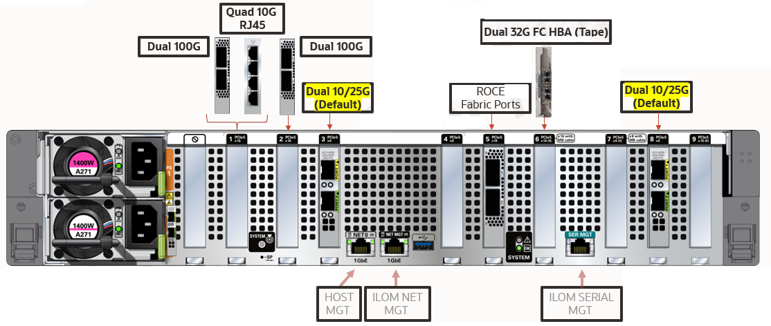
Each compute server in the RA23 configuration consists of the following network components and interfaces:
- 2 x Dual Port 10/25 Gb Ethernet SFP28
- 2 x 10/25 Gb optical (ingest)
- 2 x 10/25 Gb optical (replication)
- 2 x Dual Port 100 Gb Ethernet QSFP28
- 2 x 100 Gb optical (ingest)
- 2 x 100 Gb optical (replication)
- 1 x Quad Port 10 Gb Ethernet RJ45
- 2 x 10 Gb copper (ingest)
- 2 x 10 Gb copper (replication)
- For ingest network, maximum of
- 2 x 10 Gb Ports,
- 2 x 25 Gb Ports, or
- 2 x 100 Gb Ports
- For replication network, maximum of
- 2 x 10 Gb Ports,
- 2 x 25 Gb Ports, or
- 2 x 100 Gb Ports
- Ingest and Replication can be different, for example 100Gb for ingest and 25Gb for replication.
- Optional Ports
- Sun Storage Dual 32 Gb Fibre Channel PCIe Universal HBA, QLogic for tape connectivity
- Standard Ports
- 2 x 100 Gb QSFP28 RoCE Fabric Ports
- 1 x 1 Gb copper Ethernet Port (mgmt)
- 1 x ILOM Ethernet Port
Figure 3-1 Oracle Zero Data Loss Recovery Appliance RA23 Networking

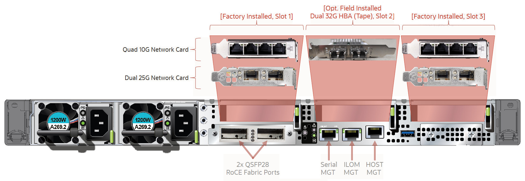
Each compute server in the RA21 configuration consists of the following network components and interfaces:
-
Ethernet ingest and replication network connectivity, :
-
2 x Dual 10/25G Network Cards, or
-
2 x Quad 10G Network Cards, or
-
1 x Quad 10G Network Card and 1 x Dual 10/25G Network Card
-
-
2 x QSFP2B RoCE Fabric Ports
-
1 Ethernet port for
Serial MGTremote management -
1 Ethernet port for
ILOM MGT(Oracle Integrated Lights Out Manager) remote management -
1 Ethernet port for
HOST MGTremote management -
Optional: Dual 32G HBA (Tape) card that can be field installed. This slot is not available for other network cards.
Figure 3-2 Oracle Zero Data Loss Recovery Appliance RA21 Backplane External Network Connectivity

Description of "Figure 3-2 Oracle Zero Data Loss Recovery Appliance RA21 Backplane External Network Connectivity"
- Maximum of two 10G (or 25G) ports for ingest and two 10G (or 25G) ports for replication, per compute server
- Maximum of four 10G (or 25G) for each network in bonded LACP configuration, per rack
- Replication can be used as separate ingest network (MOS Note 2126047.1)
- VLAN tagging supported on ingest network (MOS Note 2047411.1)
- Slot 2 cannot be used for additional network card.
Each compute server in the X8M configuration consists of the following network components and interfaces:
-
Ethernet ingest and replication network connectivity, :
-
2 x Dual 10/25G Network Cards, or
-
2 x Quad 10G Network Cards, or
-
1 x Quad 10G Network Card and 1 x Dual 10/25G Network Card
-
-
2 x QSFP2B RoCE Fabric Ports
-
1 Ethernet port for
Serial MGTremote management -
1 Ethernet port for
ILOM MGT(Oracle Integrated Lights Out Manager) remote management -
1 Ethernet port for
HOST MGTremote management -
Optional: Dual 32G HBA (Tape) card that can be field installed. This slot is not available for other network cards.
Figure 3-3 Oracle Zero Data Loss Recovery Appliance X8M Backplane External Network Connectivity

Description of "Figure 3-3 Oracle Zero Data Loss Recovery Appliance X8M Backplane External Network Connectivity"
- Maximum of two 25G ports for ingest and two 25G ports for replication, per compute server
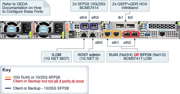
Each compute server in the X8 and X7 configuration consists of the following network components and interfaces:
-
Ethernet ingest and replication network connectivity
-
On-board: 2 x 10 Gb copper Ethernet (eth1)
-
On-board: 2 x 10/25 Gb optical Ethernet Ports (eth2)
-
PCIe card: 2 x 10/25 Gb optical Ethernet Ports (eth3 and eth4)
-
-
1 dual-port 4X QDR (40 Gbps) InfiniBand Host Channel Adapter (HCA) (IB0 and IB1)
-
1 Ethernet port for Oracle Integrated Lights Out Manager (ILOM) remote management
-
1 dual-port 32 GB FC Converged Network Adapter (CNA) FC ports 0 and 1.
Note:
The corresponding SFP modules that work with the 10/25 GbE PCIe 2.0 network cards are purchased separately.
Figure 3-4 Oracle Zero Data Loss Recovery Appliance X8 and X7 Backplane External Network Connectivity

Description of "Figure 3-4 Oracle Zero Data Loss Recovery Appliance X8 and X7 Backplane External Network Connectivity"
Given that the base rack has two (2) compute servers, the maximum for ingest is 2 x 10 Gb or 2 x 25 Gb Ethernet ports, while the maximum for replication is 2 x 10 Gb or 2 x 25 Gb Ethernet ports. The following are valid combinations of the options.
-
2 x 10Gb on-board copper (ingest) + 2 x 10/25Gb PCIe card optical (replication)
-
2 x 10/25Gb PCIe card optical (ingest) + 2 x 10Gb on-board copper (replication)
-
2 x 10/25Gb PCIe card optical (ingest) + 2 x 10/25Gb on-board optical (replication)
-
2 x 10/25Gb on-board optical (ingest) + 2 x 10/25Gb PCIe card optical (replication)
Note:
If ingest and replication traffic is desired to be configured on the same network, define the required network interface in OEDA in the ingest network section, and leave the replication network section blank. With this setup, Recovery Appliance will use the ingest network for replication traffic.Each storage server consists of the following network components and interfaces:
-
1 embedded Gigabit Ethernet port (NET0)
-
1 dual-port 4X QDR (40 Gbps) InfiniBand Host Channel Adapter (HCA) (IB0 and IB1)
-
1 Ethernet port for Oracle Integrated Lights Out Manager remote management (Oracle ILOM)
Additional configuration, such as defining multiple virtual local area networks (VLANs) for the management (NET0 and/or ILOM) interfaces or enabling routing, might be required for the switch to operate properly in your environment and is beyond the scope of the installation service. If additional configuration is needed, then your network administrator must perform the necessary configuration steps during installation of Recovery Appliance.