6 Virtualized Exadata Database Machine

This chapter describes how to manage and monitor a virtualized Oracle Exadata Database Machine with DB clusters using Oracle Virtual Machine (OVM) for x86 and Oracle Exadata Storage Servers in Exadata plug-in 13.3.2.0.0 and later.

The Exadata plug-in discovers, manages, and monitors virtualized Exadata Database Machine in conjunction with the Virtualization Infrastructure plug-in. For details about this plug-in, see Direct Monitoring of Xen Based Systems in Oracle® Enterprise Manager Cloud Administration Guide:

The following sections describe how to discover a virtualized Exadata Database Machine and other supported targets:

Once you have completed the discovery of a virtualized Exadata Database Machine, continue with the configuration steps outlined in Post-Discovery Configuration and Verification.

Exadata Virtualized Provisioning

Provisioning involves repeatable, reliable, automated, unattended, and scheduled mass deployment of a RAC Cluster including virtual machines (VMs), Oracle Database (DB), Grid Infrastructure, and ASM on Virtualized Exadata.

With the Exadata plug-in's virtualization provisioning functionality, you can:

Creating a Database Cluster

To create a database cluster:

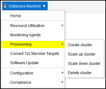
  1. From the Database Machine target menu, select Provisioning, then select Create Cluster (Figure 6-1):

    Figure 6-1 Provisioning Menu


    Provisioning Menu

    The Exadata Provisioning Wizard will display.

  2. On the Exadata Provisioning: Cluster page, provide the information for:
    • Cluster Definition: Create a cluster name. Click Show existing clusters to display a list of database clusters already provisioned.

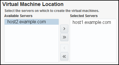
    • Virtual Machine Location: Select the servers on which you want to create the virtual machines. Select one or more from the Available Servers pane, then click the move button to move the selected server to the Selected Servers pane (Figure 6-2):

      Figure 6-2 Select Virtual Machine Location


      Select Virtual Machine Location

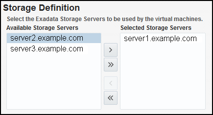
    • Storage Definition: Select the Exadata Storage Servers to be used by the virtual machines. Select one or more from the Available Storage Servers pane, then click the move button to move the selected server to the Selected Storage Servers pane:

      Figure 6-3 Select Exadata Storage Servers


      Select Exadata Storage Servers

    Click Next.

  3. On the Credentials page, set the credentials for:
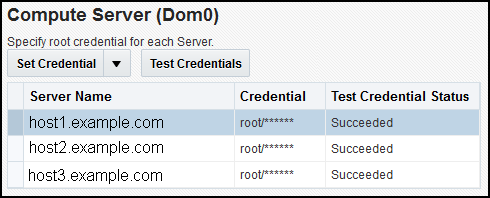
    • Compute Server: Set the credentials for the root user. From the Set Credentials drop-down, select All to apply the settings to all servers, or select one or more servers from the list and select Selected to apply the settings to only the selected servers.

      In the Set Server Credential pop-up window, select an existing named credential or select New to create a new one.

      Click Test Connection to verify that the credentials are properly set. If successful, the Test Credential Status will update to show Succeeded (Figure 6-4):

      Figure 6-4 Set Compute Server Credentials


      Set Compute Server Credentials

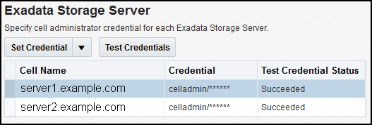
    • Exadata Storage Server: Set the credentials for the cell administrator.

      In the Set Server Credential pop-up window, select an existing named credential or select New to create a new one.

      Click Test Connection to verify that the credentials are properly set. If successful, the Test Credential Status will update to show Succeeded (Figure 6-5):

      Figure 6-5 Set Exadata Storage Server Credentials


      Set Exadata Storage Server Credentials

    Click Next to define the Virtual Machines.

  4. On the Virtual Machines (VMs) page, provide the following information:

    Note:

    When available, the Exadata Provisioning Wizard will pre-populate the fields with the appropriate defaults. You can change this information to suit your environment.

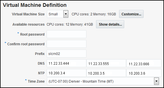
    • Virtual Machine Definition: In this region (Figure 6-6), provide the details to define the VM:

      • Virtual Machine Size: Select Small, Medium, or Large. Click Customize to adjust the number of CPU cores and available memory.

      • Root password: Create a password in the two password fields.

      • Verify the Prefix, DNS, and NTP fields.

      • Time Zone: select the appropriate time zone from the drop-down list.

      Figure 6-6 Exadata Provisioning: Virtual Machine Definition


      Exadata Provisioning: Virtual Machine Definition

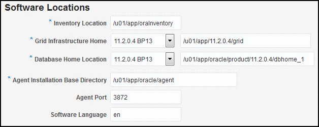
    • Software Locations: When available, the Exadata Provisioning Wizard will pre-populate the fields (Figure 6-7); otherwise, provide the following information:

      • Inventory Location

      • Grid Infrastructure Home

      • Database Home Location

      • Agent Installation Base Directory

      • Agent Port (optional)

      • Software Language (optional)

      Figure 6-7 Exadata Provisioning: Software Locations


      Exadata Provisioning: Software Locations

    • Operating System Users and Groups: Like the Software Location region, the Exadata Provisioning Wizard will pre-populate the fields except for the password fields (Figure 6-8). Otherwise, provide the following information:

      • User name: including the ID, password, and home directory.

      • DBA group name and ID.

      • OINSTALL group name and ID.

      Figure 6-8 Exadata Provisioning: Operating System Users and Groups


      Exadata Provisioning: Operating System Users and Groups

    Click Next to provide the Network details.

  5. On the Network page, specify the IP address, name and domain used for the Admin, Client and Private network. Provide the details for the following information:
    • Gateway and Domain Details: The domain and subnet mask details should already be supplied by the Exadata Provisioning Wizard. Enter a valid IP address for the Admin and Client gateway (Figure 6-9):

      Figure 6-9 Exadata Provisioning: Network Gateway and Domain Details


      Exadata Provisioning: Network Gateway and Domain Details

    • Virtual Machine 1 (Figure 6-10): For the first virtual machine in the cluster, the Exadata Provisioning Wizard will auto-complete the Prefix and Start ID field. You can enter an optional Suffix. Enter a valid IP address.

      Figure 6-10 Exadata Provisioning: Virtual Machine 1


      Exadata Provisioning: Virtual Machine 1

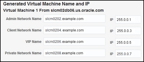
    • Generated Virtual Machine Name and IP (Figure 6-11): After you have entered the information for the first VM, click Generate to create the information for the other VMs in the cluster. You can always enter the details manually.

      Figure 6-11 Exadata Provisioning: Generated Virtual Machine Name and IP


      Exadata Provisioning: Generated Virtual Machine Name and IP

    Once you have entered all the necessary information, click Validate IP at the top of the page to verify the IP addresses. Click Next to continue to the enter the details for Grid Infrastructure and to create the Initial Database.

  6. On the Grid Infrastructure and Initial Database page, enter the details for:
    • Grid Infrastructure (Figure 6-12): Enter the details for the Cluster (SCAN name and port) and verify the Disk Group information. The Exadata Provisioning Wizard will pre-populate the details, but you can adjust them as needed.

      Figure 6-12 Exadata Provisioning: Grid Infrastructure


      Exadata Provisioning: Grid Infrastructure

    • Initial Database: Click the check box to create the initial database. Additional information for Database Identification and Administrator Credentials will be required as shown in Figure 6-13:

      Figure 6-13 Exadata Provisioning: Initial Database


      Exadata Provisioning: Initial Database

      Click Advanced to expand the region for additional details for Memory Parameters, Processes, and Character Sets as shown in Figure 6-14:

      Figure 6-14 Exadata Provisioning: Initial Database Advanced Details


      Exadata Provisioning: Initial Database Advanced Details

    Click Next to set the schedule.

  7. On the Schedule page, the Exadata Provisioning Wizard will create the Deployment Instance value. Select a schedule start and notification options:
    • Schedule: Select to initiate the creation immediately or later. If you select later, then you will be prompted to select a date and time.

    • Notification: Select the notification statuses for which you will be notified.

    Click Review to review the settings and initiate the job.

  8. On the Review page, review the selection in the summary displayed. To change any section, return to the previous page and edit the selection.

    Click Submit to begin the creation job.

Scaling Up a Database Cluster

To scale up a database cluster:

  1. From the Database Machine target menu, select Provisioning, then select Scale Up Cluster.

    The Exadata Provisioning Wizard will display.

  2. On the Cluster page, enter the cluster name or click the Search icon to select a cluster from the list.

    Select one or more from the Available Servers pane, then click the move button to move the selected server to the Selected Servers pane.

    Click Next to set the credentials.

  3. On the Credentials page, set the credentials for:
    • Compute Server: Set the credentials for the root user. From the Set Credentials drop-down, select All to apply the settings to all servers, or select one or more servers from the list and select Selected to apply the settings to only the selected servers.

      In the Set Server Credential pop-up window, select an existing named credential or select New to create a new one.

      Click Test Connection to verify that the credentials are properly set. If successful, the Test Credential Status will update to show Succeeded (Figure 6-15):

      Figure 6-15 Set Compute Server Credentials


      Set Compute Server Credentials

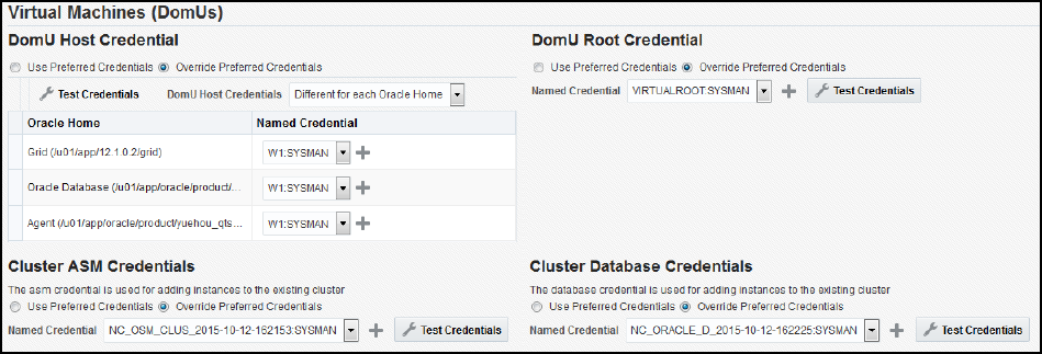
    • Virtual Machines (Figure 6-16): Set the credentials for the DomU Host and Root and for the Cluster ASM and Database.

      You have the option to use preferred credentials or to override the preferred credentials.

      Click Test Connection to verify that the credentials are properly set.

      Figure 6-16 Scale Up Cluster: Virtual Machines Credentials


      Scale Up Cluster: Virtual Machines Credentials

    Click Next.

  4. On the Virtual Machines page, click Next.
  5. On the Network page, specify the IP address, name and domain used for the Admin, Client and Private network. Provide the details for the following information:
    • Gateway and Domain Details: The domain and subnet mask details should already be supplied by the Exadata Provisioning Wizard. Enter a valid IP address for the Admin and Client gateway (Figure 6-17):

      Figure 6-17 Scale Up: Network Gateway and Domain Details


      Scale Up: Network Gateway and Domain Details

    • Virtual Machine 1 (Figure 6-18): For the first virtual machine in the cluster, the Exadata Provisioning Wizard will auto-complete the Prefix and Start ID field. You can enter an optional Suffix. Enter a valid IP address.

      Figure 6-18 Scale Up: Virtual Machine 1


      Scale Up: Virtual Machine 1

    • Generated Virtual Machine Name and IP (Figure 6-17): After you have entered the information for the first VM, click Generate to create the information for the other VMs in the cluster. You can always enter the details manually.

      Figure 6-19 Scale Up: Generated Virtual Machine Name and IP


      Scale Up: Generated Virtual Machine Name and IP

    Once you have entered all the necessary information, click Validate IP at the top of the page to verify the IP addresses.

    Click Next to continue to schedule the scale up.

    Note:

    The step for Grid Infrastructure and Initial Database are skipped because they do not need to be set up again.

  6. On the Schedule page, the Exadata Provisioning Wizard will create the Deployment Instance value. Select a schedule start and notification options:
    • Schedule: Select to initiate the scale up immediately or later. If you select later, then you will be prompted to select a date and time.

    • Notification: Select the notification statuses for which you will be notified.

    Click Review to review the settings and initiate the scale up.

  7. On the Review page, review the selection in the summary displayed. To change any section, return to the previous page and edit the selection.

    Click Submit to begin the scale up.

Scaling Down a Database Cluster

To scale down a database cluster, the Virtual Machine is removed from the cluster:

  1. From the Database Machine target menu, select Provisioning, then select Scale Down Cluster.

    The Exadata Provisioning Wizard will display.

  2. Enter the cluster name you want to scale down or click the Search icon to select an available cluster.

    Once you have selected a cluster, you will be prompted to:

    • Select nodes to delete.

    • Verify or enter new named credentials for DomU (host, root, and Exadata Server) and for the Exadata Storage Server. Click Test Credentials to verify the credentials have been selected properly.

    Click Next to schedule the scale-down job.

  3. On the Schedule page, the Exadata Provisioning Wizard will create the Deployment Instance value. Select a schedule start and notification options:
    • Schedule: Select to initiate the scale down immediately or later. If you select later, then you will be prompted to select a date and time.

    • Notification: Select the notification statuses for which you will be notified.

    Click Review to review the settings and initiate the scale down.

  4. On the Review page, review the selection in the summary displayed. To change any section, return to the previous page and edit the selection.

    Click Submit to begin the scale down.

Deleting a Database Cluster

To delete an existing cluster:

  1. From the Database Machine target menu, select Provisioning, then select Delete Cluster.

    The Exadata Provisioning Wizard will display.

  2. On the Cluster page, enter the cluster name you want to delete or click the Search icon to select an available cluster.

    The page will update to show the nodes to be deleted

    Verify or enter new named credentials for DomU (host, root, and Exadata Server) and for the Exadata Storage Server. Click Test Credentials to verify the credentials have been selected properly.

    Click Next to schedule the delete job.

  3. On the Schedule page, the Exadata Provisioning Wizard will create the Deployment Instance value. Select a schedule start and notification options:
    • Schedule: Select to initiate the scale down immediately or later. If you select later, then you will be prompted to select a date and time.

    • Notification: Select the notification statuses for which you will be notified.

    Click Review to review the settings and initiate the delete job.

  4. On the Review page, review the selection in the summary displayed. To change any section, return to the previous page and edit the selection.

    Click Submit to begin the delete job.

Viewing Virtualized Exadata Database Machine

Once discovered, the Exadata plug-in shows the virtual machines monitored by Enterprise Manager Cloud Control, as shown in Figure 6-20:

Figure 6-20 Virtual Machines Monitored


Virtual Machines Monitored

Note:

The schematic diagram in the Database Machine home page is based on the content of the databasemachine.xml file found during discovery. The virtual platforms (Dom0) are displayed as compute nodes in the rack in the schematic diagram.

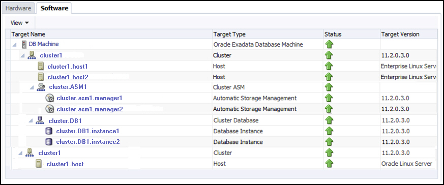
The Database Machine Software topology diagram will not display the physical Oracle Server, virtual Oracle Server targets (DomU), and Virtual Platform target (Dom0) targets. However, it will continue to show the host targets which are running in DomU.

The Software tab for the Exadata Database Machine target shows all clusters, ASM, and Database targets in the whole physical Database Machine grouped by clusters as described in Figure 6-21:

Figure 6-21 Exadata Database Machine Software Tab

Exadata Database Machine Software Tab

Resource Utilization Graphs

The following compute resource allocation graphs are available in virtualized Exadata. These graphs are dependent on the virtual machine hierarchy and metric data from the VI plug-in:

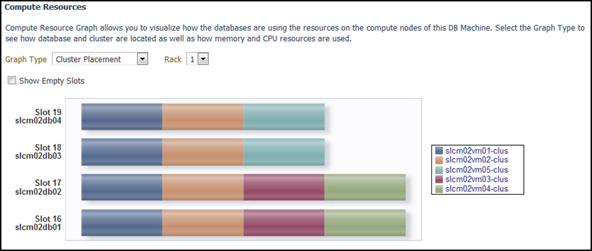
Cluster Placement

This graph (Figure 6-22) shows the ClusterWare cluster placement on physical servers in a particular Exadata Database Machine rack. Since this is a placement graph, the widths of the data series reflect the number of clusters on the physical server that has the most number of clusters.

Figure 6-22 Resource Utilization: Cluster Placement

Resource Utilization: Cluster Placement

Database Placement

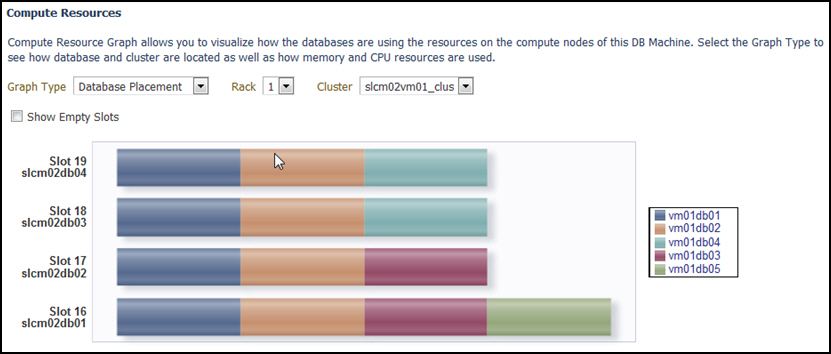
This graph (Figure 6-23) shows the database placement on physical servers in a particular Exadata Database Machine rack for a particular DB cluster. Since this is a placement graph, the widths of the data series reflect the number of DB on the physical server that has the most number of databases for a particular DB cluster.

Figure 6-23 Resource Utilization: Database Placement

Resource Utilization: Database Placement

Database CPU Utilization

This graph (Figure 6-24) shows the database CPU utilization per database per VM host for a particular DB cluster.

Figure 6-24 Resource Utilization: Database CPU Utilization
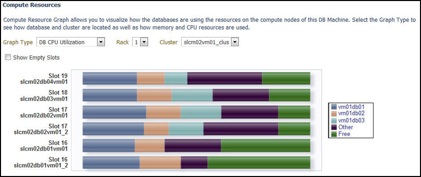

Resource Utilization: Database CPU Utilization

Database Memory Utilization

This graph (Figure 6-25) shows the database memory utilization per database per VM host for a particular DB cluster.

Figure 6-25 Resource Utilization: Database Memory Utilization
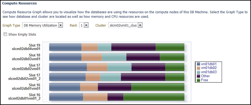

Resource Utilization: Database Memory Utilization