3 APPD Card Overview
This chapter presents an overview of the APPD card package, components, and adapter interfaces.
Note:
For the complete list of cards supported by EAGLE Release 48.0, see Hardware Reference Guide.3.1 Introduction
The APPD card is a dual-slot EAGLE card designed as the replacement for E5-APP-B cards. They are based on a common processor motherboard architecture that is shared with the SLIC V3 design and is intended to support both legacy E5-APP-B applications and future application deployments. APPD card packages are designed to be integrated with features that run on a Signal Transfer Point (STP). APPD cards for these applications run in a Direct Current (DC) environment and are delivered as a pair to be installed in an EAGLE using heavy duty frames, along with breaker panels and Ethernet communication equipment.
Note:
The APPD Card is not IMT Bus capable.For more information about EAGLE shelves, see the EAGLE Hardware Guide.
This chapter provides an overview of APPD cards and highlights APPD card features, components, and adapter interfaces.
3.2 APPD Card
An APPD card comes with two removable drive modules when first ordered. A complete shipping package for applications includes:
-
Two standard APPD EAGLE double-wide cards, identified as A and B, are deployed as a redundant pair. Each APPD card includes two front-accessible SATA solid-state drives (SSDs) configured for redundant RAID operation. The SSDs support hot-swappable replacement, allowing a failed drive to be replaced while the system remains operational. Each APPD card is loaded at the factory with platform software and application software.
-
Two removable drive modules for each separate card. For more information about these components, refer to the documentation delivered with the product.
Note:
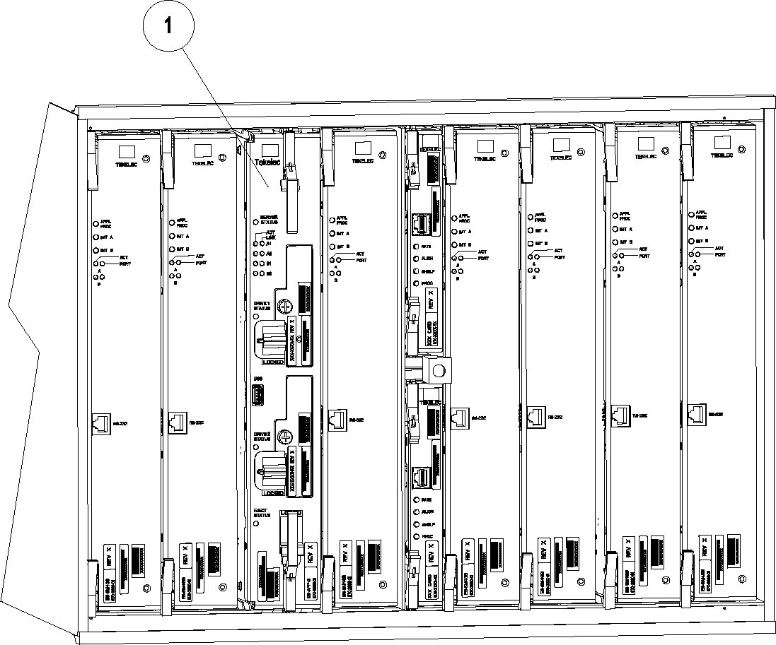
The APPD cards have a capacity of 1.92T each.Figure 3-1 shows an example APPD card in a shelf(1).
Figure 3-1 APPD Card In Shelf
Compatible Applications and Card Types
The following table shows which applications can run on the APPD card:
Table 3-1 Application and Card Type Compatibility
| Application | Card Type(s) |
|---|---|
| ELAP | APPD |
| EPAP* | APPD |
| LSMS | APPD |
3.3 APPD Card Features
A single APPD card is a general-purpose application server (AS) that offers high transaction rates with low latency. It supports a variety of application solutions for the wireless and wireline telecommunications infrastructure to provide the building blocks for next-generation signaling systems.
The APPD card is a scalable computing platform constructed with state-of-the-art components packaged on a double-wide card designed to fit into two slots of an EAGLE shelf. Each APPD card has two removable drive modules. APPD cards are installed in pairs for redundancy and high availability.
Figure 3-2 shows a single APPD card. This view shows where hardware components, especially Field Replaceable Units (FRUs), are located.
Figure 3-2 APPD Card
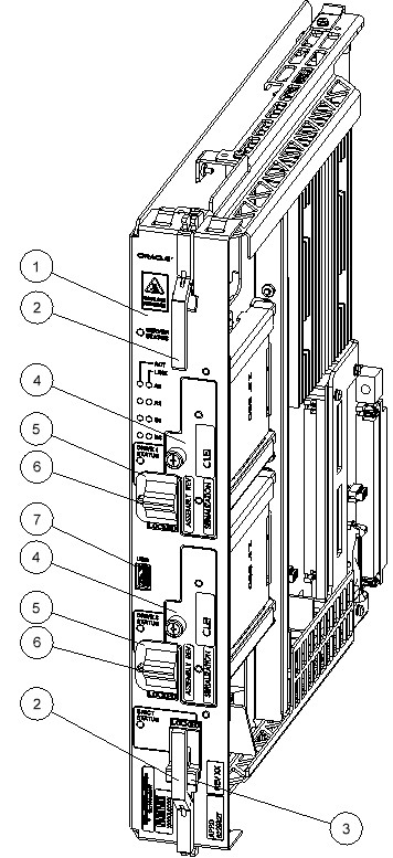
The following are Field Replaceable Units:
- APPD card (1)
- Drive Module (4)
For more information about FRUs, see the corresponding Alarms and Maintenance guide included in this release.
The other features components are:
- Injector/Ejector (2)
- Ejector Switch (3)
- Drive module locking switch (5)
- Switch lock release (6)
- USB Port (7) - Used for software upgrades
APPD Card Status Indicators
Figure 3-3 APPD Card Indicators
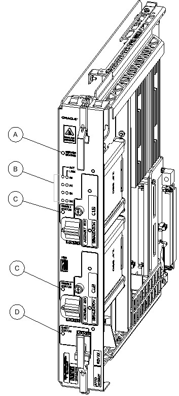
The following light-emitting diode (LED) status indicators (see Figure 3-3) can be found on the APPD card:
- One Server Status indicator (A)
- Four E-Net link and Active LED status indicators (B)
- Two drive module status indicators (C)
- One Card Eject status indicator (D)
For more information about the diagnostics that manage these alarm and status indicators, see APPD Card Diagnostics.
APPD Card Installation
A single APPD card is installed in two adjacent EAGLE shelf slots. To install two APPD cards for redundancy (the recommended configuration), the EAGLE must have room to install two double-width cards.
3.4 APPD Card Components
The APPD card consists of the following standard hardware components:
- Embedded application processing platform with CPU Intel(R) Xeon(R) CPU @ 2.30GHz
- Minimum 32 GB of ECC-protected main memory
- BIOS storage implemented in non-volatile flash memory
- Four 10/100/1000 Ethernet interfaces
- Four RS232 interfaces
- One front-panel USB interface
- Light Emitting Diode (LED) status indicators
- Hardware watchdog functionality
- Hardware monitoring and reporting capabilities:
- Fan alarm monitoring
- Voltage monitoring and fault detection
- Board reset status monitoring
- Two front-accessible, hot-swappable SATA solid-state drives (SSDs), designated as Field-replaceable Units (FRUs)
3.5 APPD Card Interfaces
The APPD card includes interfaces that support system connectivity, control and configuration functions, removable storage, and peripheral access. summarizes the basic interfaces provided by the APPD card.
Table 3-2 APPD Card Interfaces
| Interface | Description |
|---|---|
| Four Serial Interfaces | Standard RS232 interfaces used for connectivity to external equipment. |
| One USB Port | Front-panel USB interface that provides direct connectivity to peripheral devices. |
| Fan Alarm Interface | Supports fan alarm monitoring regardless of the EAGLE shelf in which the APPD card is installed, including the 6200 and 6300 shelves. |
| Four Gigabit Ethernet Interfaces | Four 10/100/1000 Ethernet ports used for network connectivity. |
| Two Hot-Swappable SATA SSDs | Two front-accessible SATA solid-state drives (SSDs) that support hot-swappable replacement, allowing a failed drive to be replaced while the system remains operational. |
3.6 Electrical Features
The APPD card has the following standard electrical features:
- Operates from an input voltage range of -40 VDC to -60 VDC.
- Includes a safety fuse on the -48 VDC input.
- Includes voltage monitoring circuitry that prevents board initialization or operation when board voltages are not within specification.
- Supports software detection of board resets caused by on-board voltage failures.
- Supports operation in EAGLE systems that provide -48 VDC power through the backplane.
- The APPD shall not exceed 78 watts of power consumption.
- The APPD shall continue normal operation when subjected to telecommunications power transients specified by ANSI T1.315.
- The APPD shall automatically recover from specified transient conditions.
3.7 Mechanical Design and Maintenance Features
The APPD card mechanical design meets all applicable NEBS requirements and is designed to protect all active components. The design has efficient component cooling using low-impedance air paths, and its compact size allows multiple units to be configured in a shelf with zero clearance.
The APPD card has been designed for easy maintenance. The following components are Field-replaceable Units (FRUs):
- The APPD card
- Drive Module Assembly
Device: /dev/sdX [SAT], SMART Failure: FAILURE PREDICTION THRESHOLD
EXCEEDED: ascq=0xNN"/dev/sdX" and replace it as soon as possible.
The Mean Time to Repair (MTTR) for the APPD shall be less than or equal to 30 minutes. The APPD is designed with a component life-cycle objective of at least five years from the general availability (GA) date of the product.
3.8 APPD Card Diagnostics
All components that comprise the APPD card platform are designed for testability to ensure that operational status can be accurately determined and that appropriate levels of fault detection and isolation are possible with a minimum of effort.
The APPD supports automated functional testing of active components and in-circuit testing (ICT) to verify electrical connections and hardware integrity.
Diagnostics enable troubleshooting of installed systems by verifying operational capability of Field Replaceable Units (FRU) and operational status of peripheral system components (such as cables and connectors) through automated testing initiated by FRU components.
- Minimum 90% automated functional test coverage of active components
- Minimum 95% in-circuit test (ICT) coverage
- Built-in diagnostics to support customer service loopback and diagnostic testing
- Hardware watchdog monitoring and watchdog diagnostic capabilities
- Elapsed Time Counter (ETC) for operational tracking and maintenance analysis
Table 3-3 APPD LED Table
| LED Name | HW/SW Controlled | Description |
|---|---|---|
| Server Status | SW |
Solid Red - Server is halted Flashing Red - Server is booting Solid Amber - TKLC configuration beginning Solid Green - TPD loaded/operational state Flashing Green - Server is shutting down |
| Drive 1 Status | SW/HW |
HW: Flashing Green - Drive activity SW: Flashing Red - Impending drive removal SW: Steady Red - Drive ready for removal |
| Drive 2 Status | SW/HW |
HW: Flashing Green - Drive activity SW: Flashing Red - Impending drive removal SW: Steady red - Drive ready for removal |
| Eject Status | SW |
Red - Card ready for extraction Flashing Red - Card preparing for extraction Off - Card is not ready for extraction |
| Act LED A1 | HW | Flashing Green - Link Activity |
| Act LED A2 | HW | Flashing Green - Link Activity |
| Act LED B1 | HW | Flashing Green - Link Activity |
| Act LED B2 | HW | Flashing Green - Link Activity |
| Link LED A1 | HW |
Green - 10/100 Link Speed Amber - 1000 Link Speed |
| Link LED A2 | HW |
Green - 10/100 Link Speed Amber - 1000 Link Speed |
| Link LED B1 | HW |
Green - 10/100 Link Speed Amber - 1000 Link Speed |
| Link LED B2 | HW |
Green - 10/100 Link Speed Amber - 1000 Link Speed |