4 Installing and Removing APPD Cards
This chapter covers provisioning rules and installation and removal procedures for APPD cards.
4.1 Introduction
This chapter describes how to install and remove an APPD card from an EAGLE shelf, as well as shut down procedures for specific applications.
Note:
APPD cards are installed in an EAGLE in pairs to operate redundantly and provide high availability service.Although installed in an EAGLE slot in an EAGLE shelf, an APPD card does not use the IMT bus. However, the APPD card does use power provided by the EAGLE frame. Because the APPD card is not detected on the IMT bus, it is not calculated into the power consumption needs of the unit; Therefore, certain power requirements apply to the APPD card. Refer to the Obtaining the EAGLE Power Calculator to manually determine EAGLE frame power consumption needs with the APPD card installed.
4.2 Provisioning Rules for APPD Cards
Note:
In order to facilitate the ability to use a common spare APPD card for all applications, spare APPD cards are delivered with only the 64-bit version of the Oracle Communications Tekelec Platform (TPD) operating system pre-installed. When replacing an existing LSMS APPD card with a spare APPD card, ensure that the card has the 32-bit version of TPD installed. Refer to the TPD Initial Product Manufacture User's Guide for assistance. For all applications (including LSMS), after verifying that the TPD version is correct, refer to the application-specific Installation/Upgrade Procedure to install the application.- APPD cards must be installed on separate power feeds within the shelf for redundancy purposes.
- APPD cards must be installed in odd number slot locations (i.e., xx01, xx03, xx05, etc.).
- Fan trays (890-0001-xx) are required for all EAGLE shelves that host an APPD card.
- Air management cards must be placed in open full-height slots within the shelf to provide proper air flow to the APPD cards.
- APPD based Oracle Communications EAGLE LNP Application Processor (ELAP) or EAGLE Application Processor Provisioning (EPAP) systems do not support DSM cards (870-1984-xx). DSM cards must be replaced with Oracle Communications EAGLE Service Module (E5-SMxG) cards.
4.2.1 APPD Fan Alarms
APPD cards that are being deployed in a remote EAGLE shelf or in EAGLE shelf 6200 or 6300 will have adapters and fan alarm cables installed so the application will receive Fan Alarms through the application Graphical User Interface (GUI).
APPD cards that are deployed in EAGLE shelf 1200 through 6100 will not have fan alarm cables and adapters. Fan alarms are displayed on the EAGLE terminal.
4.2.2 IMT Bus
- APPD cards for EPAP will not be on the IMT bus regardless of placement in an existing EAGLE shelf. However, they can be deployed in EAGLE shelves connected to the IMT bus if the frame is in the EAGLE line-up.
- The APPD card must be provisioned and its power consumption specified when the card is installed in any slot in the 1100 through 6300 shelves so that its power consumption may be included with the EAGLE Power Calculations.
- Other EAGLE cards can be used in shelves connected to the IMT bus.
- EAGLE shelf positions 6200 and 6300 do not connect to the IMT bus (existing EAGLE shelf limit on IMT bus remains 16).
4.2.3 APPD Power Guidelines
- Dual 60 A power feeds are recommended for all frames that host D series cards. EAGLE frames that host D series cards may require dual 60 Amp power feeds, depending on frame configuration.
- Frames equipped with 30 A power feeds/FAP can support one shelf with a fan assembly but an upgrade to 60A power feeds/FAP is recommended.
- Frames equipped with 40 A power feeds/FAP can support two shelves with fan assemblies, but an upgrade to 60A power feeds/FAP is recommended.
- For non-standard frame configurations, use the Power Calculator Tool (SS005963) to determine if adequate power feeds exist at the customer site. For more information on Obtaining the EAGLE Power Calculator, see the following section.
4.2.5 APPD Card Distance Limitations
- 328 Feet (100 Meters) maximum cable length between Switches and EAGLE Service Modules.
- 100 Feet (30.5 Meters) maximum cable length between APPD cards and Switches for serial connectivity
- 100 Feet (30.5 Meters) maximum cable length between APPD cards and EAGLE Control Shelf for serial MMI connectivity to the B server card (Optional: EPAP only)
- 328 feet (100 Meters) maximum cable length between Switches and APPD
4.3 Installing an APPD Card
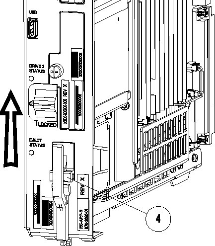
- On the APPD card, slide the Ejector switch (4) up to the UNLOCKED position. See Figure 4-1.
Figure 4-1 APPD Card Inject Hardware Switch, UNLOCKED
- Push in the top and bottom inject/eject clamps (see Figure 4-2).
Figure 4-2 APPD Card Inject Levers
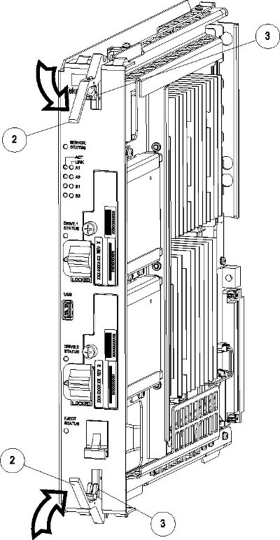
This locks the card in place and ensures a strong connection with the pins on the target shelf backplane.
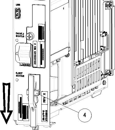
- Slide the APPD H/S switch (4) down to the LOCKED position (see Figure 4-3).
Note:
When the Ejector switch goes from UNLOCKED to LOCKED, the APPD Eject Status LED blinks red as the E5-MASP card goes online.Figure 4-3 APPD Card Inject Hardware Switch, LOCKED
4.4 Removing an APPD Card
Procedure - Remove APPD card
Note:
Theshutdown, init 6 or halt commands will not shut down the APPD card.
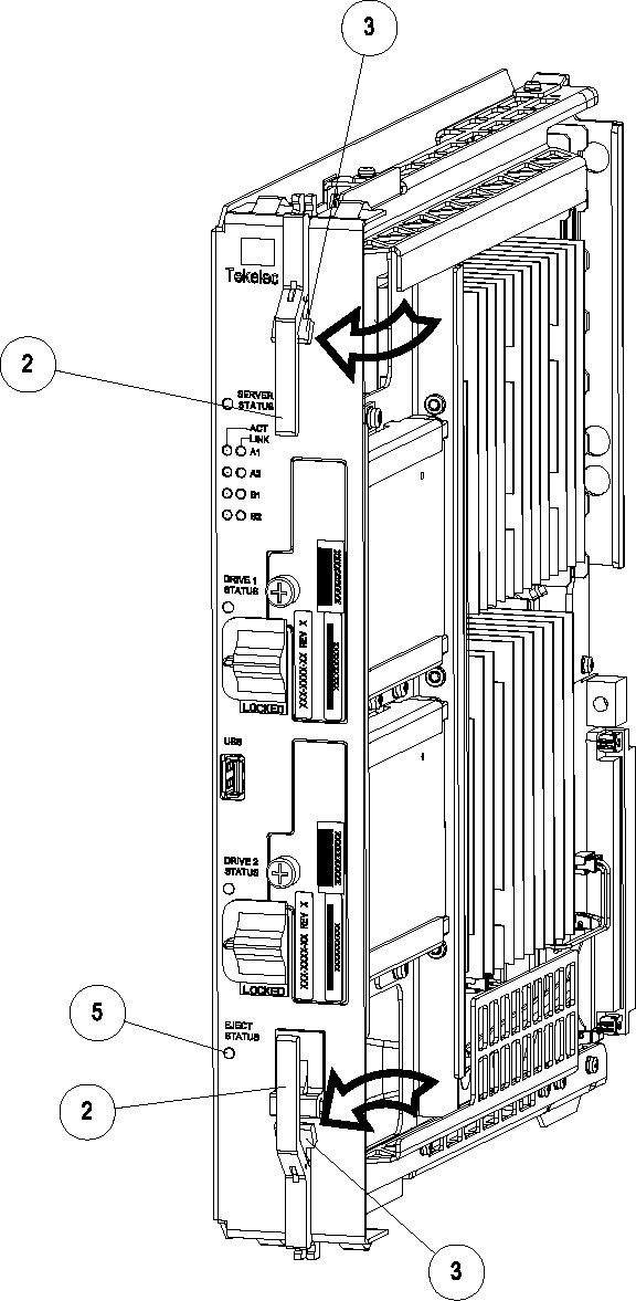
- On the APPD card, slide the Ejector switch (4) up to the UNLOCKED position (see Figure 4-4).
Caution:
When the Ejector switch goes from locked to unlocked and the APPD card is in service, the card will halt.Figure 4-4 APPD Card Eject Hardware Switch, UNLOCKED
- Grasp the upper and lower card Inject/Eject (I/E) lever release (3) just underneath the I/E lever, and press it to meet the I/E lever. This is the mechanical interlock for the card.
4.5 APPD Card Adapter Interfaces
- 1 Gigabit (Gb) Ethernet (830-1102-03)
- Serial (830-1407-01)
- Fan alarm
4.6 Changing Passwords
For security purposes, Oracle recommends that all default passwords be changed and kept in a secure location.
-
To change the passwords for APPD platforms, refer to the application guide for the application loaded on each server.
Note:
There should always be a person on-site who knows the new passwords. If there is a need to contact the My Oracle Support (MOS), provide the passwords on request.