4 Configuring Service Communication Proxy using the CNC Console
This chapter provides information about how to configure and modify different services in Service Communication Proxy (SCP) using the Oracle Communications Cloud Native Configuration Console (CNC Console).
The REST API configurations can also be performed using the CNC Console.
4.1 Support for Multicluster Deployment
The CNC Console supports both single and multiple cluster deployments.
In a single cluster deployment, the CNC Console can manage NFs and Oracle Communications Cloud Native Environment (OCCNE) common services deployed in the local Kubernetes clusters.
In a multicluster deployment, the CNC Console can manage NFs and OCCNE common services deployed in the remote Kubernetes clusters. For more information about single and multiple cluster deployments, see Oracle Communications Cloud Native Configuration Console Installation, Upgrade, and Fault Recovery Guide .
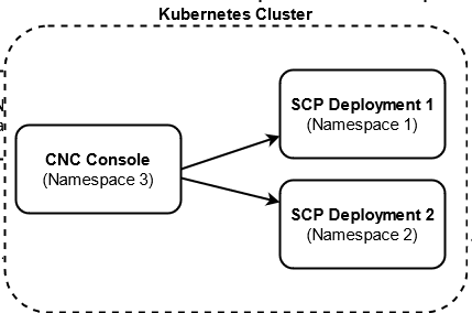
With the support of multicluster deployment, a single instance of the CNC Console can configure two or multiple instances of SCP deployments if both CNC Console and SCP instances are deployed in the same Kubernetes cluster with different namespaces.
The following image represents a Kubernetes cluster with one instance of CNC Console and two instances of SCP. The single instance of the CNC Console is configuring two instances of SCP with different namespaces.
Figure 4-1 Support for Multicluster Deployment
4.2 CNC Console Interface
This section provides an overview of the CNC Console to configure SCP features.
C:\Windows\System32\drivers\etc location.
-
In the Windows system, open the hosts file in the notepad as an Administrator and append the following set of lines at the end:
<CNCC Node IP> cncc-iam-ingress-gateway.cncc.svc.cluster.local <CNCC Node IP> cncc-core-ingress-gateway.cncc.svc.cluster.localExample:10.75.212.88 cncc-iam-ingress-gateway.cncc.svc.cluster.local 10.75.212.88 cncc-core-ingress-gateway.cncc.svc.cluster.localNote:
The IP Address in the above lines may change when deployment cluster changes. - Save and close the hosts file.
Before logging in to the CNC Console, create a CNC user and password. Log in to the CNC Console using the same credentials. For information about creating a CNC Console user and password, see Oracle Communications Cloud Native Configuration Console Installation, Upgrade, and Fault Recovery Guide .
Logging in to the CNC Console and Selecting an SCP Instance
Perform the following procedure to log in to the CNC Console and select the required SCP instance to configure SCP features.
- Open any web browser.
- Enter the URL:
http://<host name>:<port number>.Where,
<host name>is cncc-iam-ingress-ip and<port number>is cncc-iam-ingressport. - Enter the login credentials.
- Click Log
in.
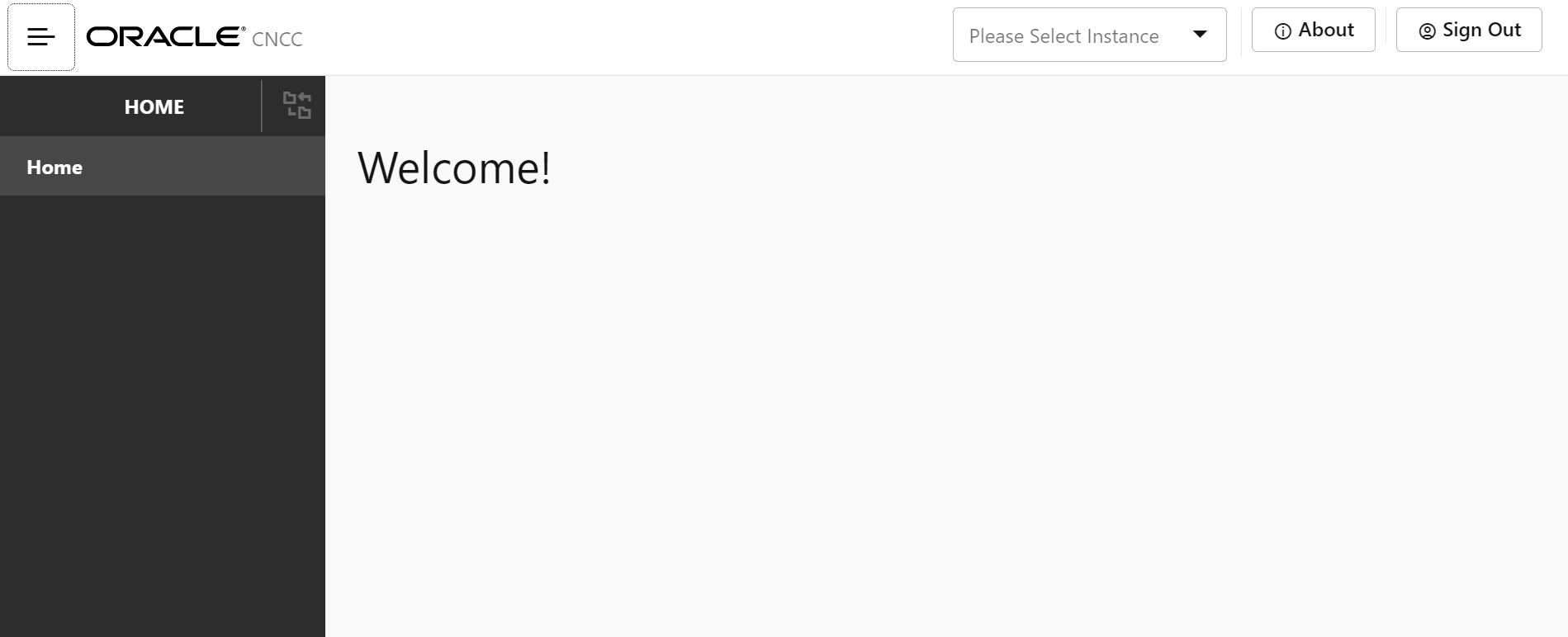
The CNC Console Home page appears.
Figure 4-2 CNC Console Welcome Screen
- In the upper pane, from the Please Select
Instance drop-down list, select the required SCP
instance.
The SCP tab appears in the left navigation pane.
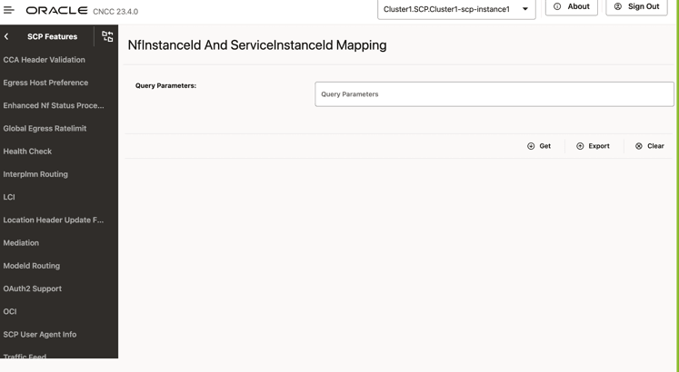
Figure 4-3 Select NF Instance
 The Please Select Instance drop-down list provides NF instances to configure corresponding NF features. You must select an appropriate SCP instance to configure SCP features. Alternatively, you can click one of the following interface elements on the Welcome screen:
- About: This element provides the CNC Console product name and version.
- Sign Out: This element exits the CNC Console.
4.2.1 Configuring SCP Features
Note:
You must log in to the CNC Console while performing the procedures described in the subsequent subsections.- Configuring Enhanced NF Status Processing
- Configuring Global Egress Rate Limiting
- Configuring Support for 5G SBI Roaming
- Configuring Mediation
- Configuring Model D Indirect 5G SBI Communication
- Configuring SCP User Agent Info
- Configuring Message Feed
- Configuring Load Control Information (LCI)
- Configuring Host Preference for Egress Message Requests
- Configuring CCA Header Validation
- Configuring Location Header Update for Host Mismatch
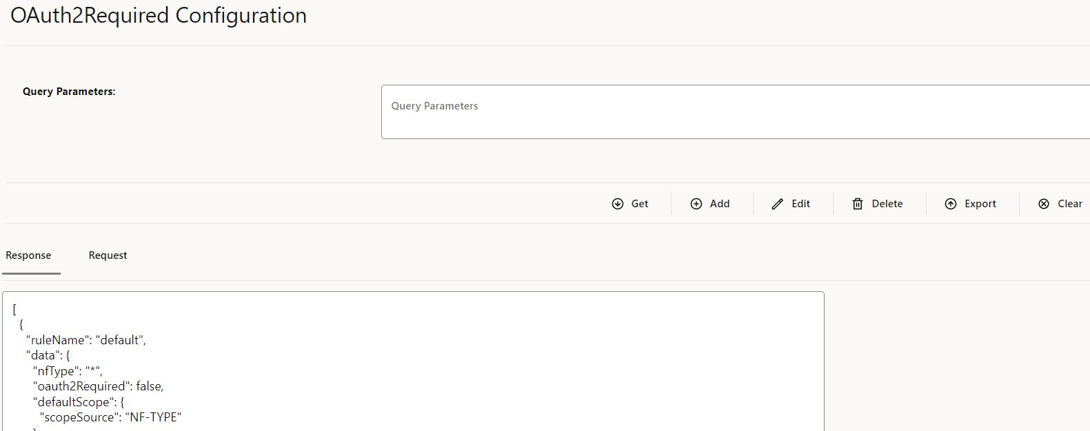
- Configuring Support for OAuth2.0
- Configuring SCP Health Check API
- NRF Configuration using DNS SRV Resolution
- Configuring Overload Control Based on the Overload Control Information Header
- Configuring Enhanced NFProfile Processing
4.2.1.1 Configuring Enhanced NF Status Processing
Perform the following procedure to enable the support for creating or retaining SCP routing rules for NF Profiles with NF Status as SUSPENDED.
Note:
The Enhanced NF Status Processing feature is applicable only when nnrf-nfm (NRF Management) service is used as an audit service for SCP.- In the left navigation pane, click the SCP tab, and then click the SCP Features tab.
- From the SCP Features list, click Enhanced Nf Status Processing.
- In the Enhanced NF Status section, click
Edit.
Figure 4-4 Editing Enhanced Nf Status Processing

- Set Enabled to true.
By default, this option is set to false.
- In the Feature Specific Config section, configure the
following fields as required:
- Enhanced Suspended State Routing: Enter the list of valid NF types for Mode 3 routing.
- Suspended State Routing: Enter the list of valid NF types for Mode 2 routing.
- Click Save.
4.2.1.2 Configuring Global Egress Rate Limiting
- In the left navigation pane, click the Global Egress Rate Limiting tab.
- In the Global Egress Rate Limit section,
click Edit.
The Edit Global Egress Rate Limit screen appears.
Figure 4-5 Enabling the Global Egress Rate Limiting
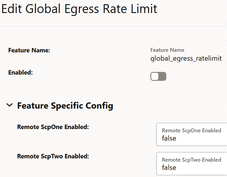
- Set Enabled to true.
By default, this option is set to false.
- In the Feature Specific Config section,
configure the following fields:
- Remote ScpOne Enabled: Set this field to true if
you want to enable egress rate aggregation with the SCP instance as defined in the
coherence.federation.remoteScpOneparameter of theocscp-custom-values.yamlfile. By default, this value is set to false. - Remote ScpTwo Enabled: Set this field to true if
you want to enable egress rate aggregation with the SCP instance as defined in the
coherence.federation.remoteScpTwoparameter of theocscp-custom-values.yamlfile. By default, this value is set to false.
- Remote ScpOne Enabled: Set this field to true if
you want to enable egress rate aggregation with the SCP instance as defined in the
- Click Save.
4.2.1.3 Configuring Support for 5G SBI Roaming
Note:
Ensure that one local and one remote PLMNs are configured before enabling this feature. To configure a remote PLMN, see Configuring SEPP Inter PLMN Routing. A local PLMN is configured at the time of SCP deployment or by editing the CUSTOM_ORACLE_SCP NF type as described in Configuring NF Rule Profile.- In the left navigation pane, click the Interplmn Routing tab.
- In the Interplmn Routing section,
click Edit.
The Edit Interplmn Routing screen appears.
Figure 4-6 Inter PLMN Routing

- Set Enabled to true.
By default, this option is set to false.
- Click Save.
4.2.1.4 Configuring Mediation
- In the left navigation pane, click the Mediation tab.
- In the Mediation section, click
Edit.
The Edit Mediation screen appears.
Figure 4-7 Enable Mediation
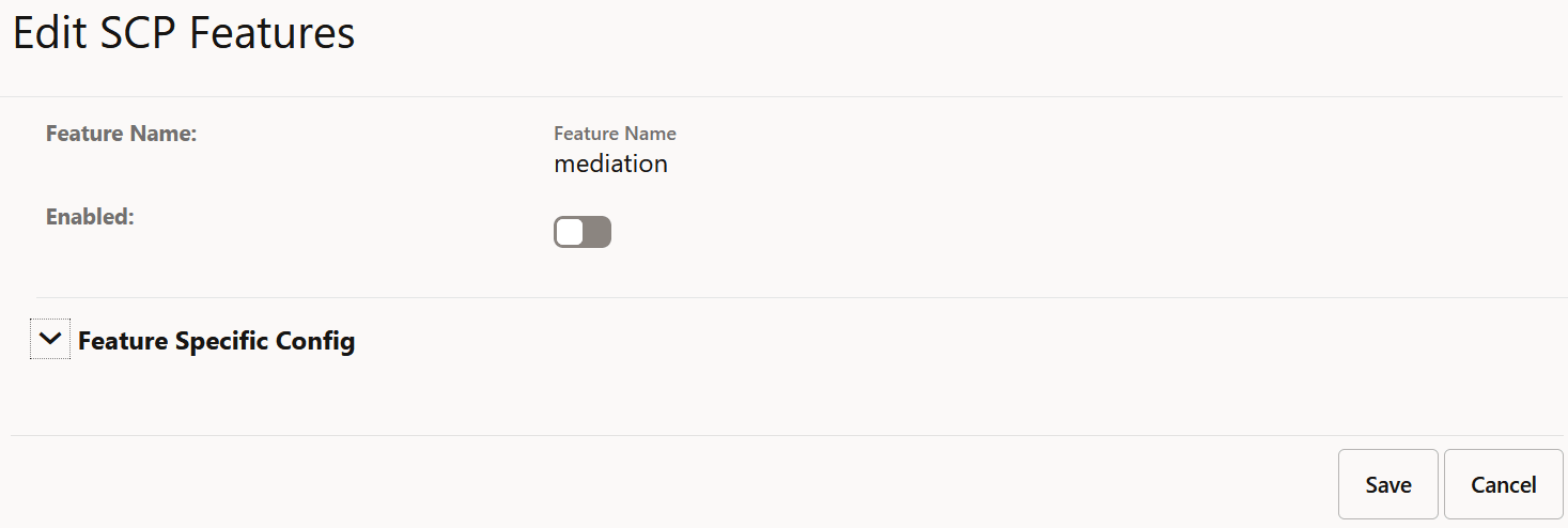
- Set Enabled to true.
By default, this option is set to false.
- Click Save.
4.2.1.5 Configuring Model D Indirect 5G SBI Communication feature
Perform the following to configure Model D indirect 5G SBI communication feature.
- In the left navigation pane, click the Modeld Routing tab.
- In the Modeld Routing section, click
Edit.
Figure 4-8 Enabling ModelD Routing
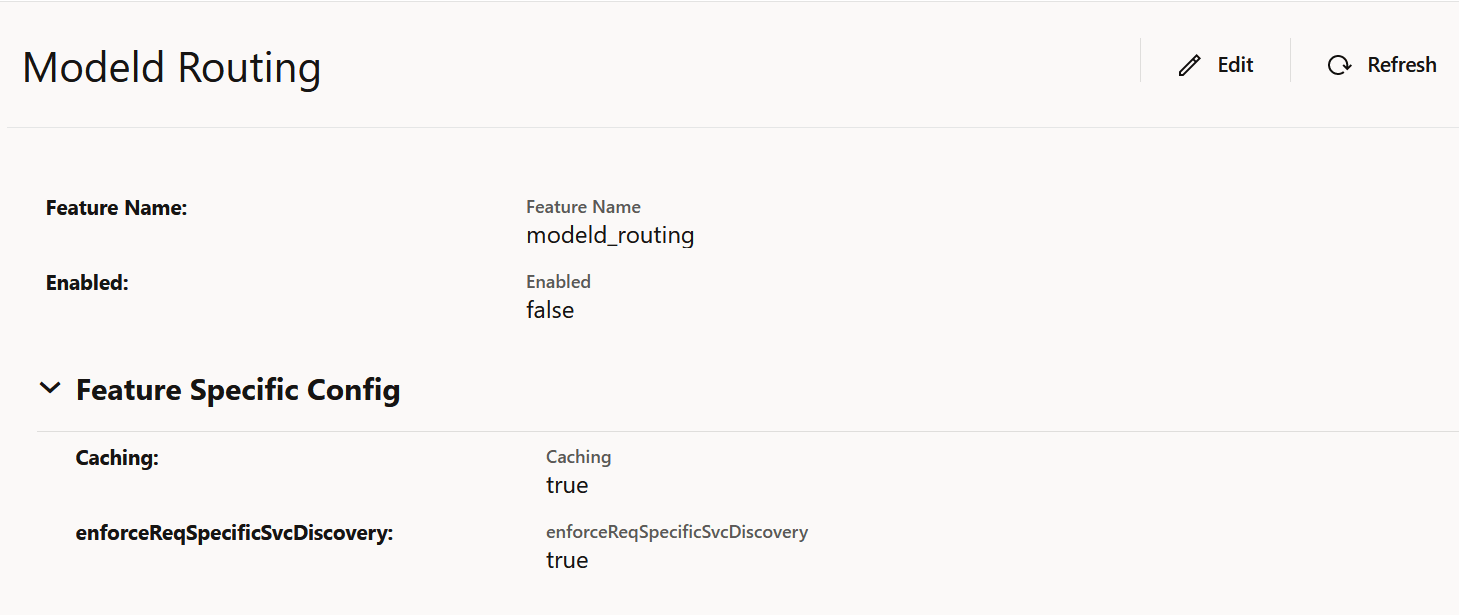
The Edit Modeld Routing screen appears.
- Set Enabled to true.
By default, this option is set to false.
- Set Caching to true or false to enable or disable caching to store discovery responses. By default, this option is set to true.
- Set enforceReqSpecificSvcDiscovery to true or false to to enable or disable NF Service specific Discovery Requests when possible. By default, this option is set to true.
- Click Save.
4.2.1.6 Configuring SCP User Agent Info
Perform the following to configure SCP User Agent Info.
- In the left navigation pane, click the SCP User Agent Info tab.
- In the SCP User Agent Info section, click
Edit.
The SCP User Agent Info screen appears.
Figure 4-9 SCP User Agent Info

- Set Enabled to true.
By default, this option is set to false.
- Expand the Feature Specific Config option, in the
User Agent Header Format field, select the required
format to set the "User-Agent" header format.
For more information about the "User-Agent" header formats, see "Configuring SCP Features" in Oracle Communications Cloud Native Core, Service Communication Proxy REST Specification Guide.
- Click Save.
4.2.1.7 Configuring Message Feed
Perform the following to configure message feed.
- In the left navigation pane, click the Traffic Feed tab.
- In the Traffic Feed section, click
Edit.
The Traffic Feed screen appears.
Figure 4-10 Message Feed

- Set Enabled to true.
By default, this option is set to false.
- Click Save.
4.2.1.8 Configuring Load Control Information (LCI)
Perform the following procedure to enable configuring load control information (LCI).
- In the left navigation pane, click the LCI tab.
- In the LCI section, click
Edit.
Figure 4-11 Editing LCI
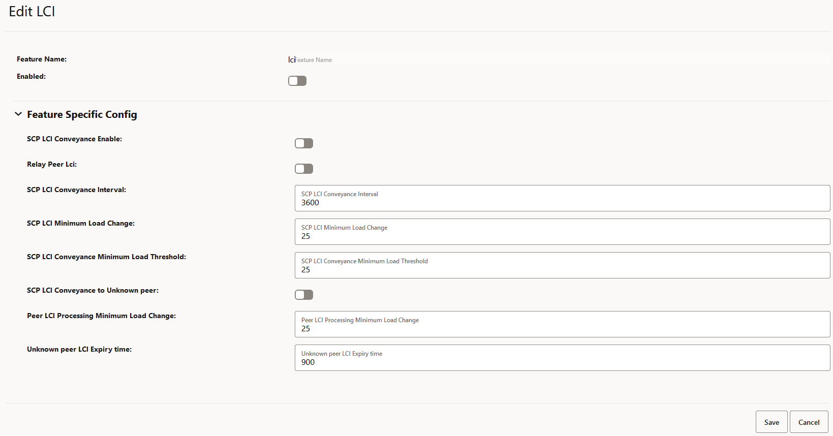
- Set Enabled to true.
By default, this option is set to false.
- In the Feature Specific Config section, complete the
following configurations:
Note:
All the parameters are mandatory to configure the LCI feature.- SCP LCI Conveyance Enable: Set to true to enable SCP to add its LCI in request and response.
- Relay Peer Lci: Set to true to allow SCP to forward the received LCI header from producer NF.
- SCP LCI Conveyance Interval: Enter a value from 100 milliseconds to 3600000 milliseconds to report the SCP LCI update interval.
- SCP LCI Minimum Load Change: Enter a value from 0 to 25 to report the minimum delta value when reporting LCI based on load change.
- SCP LCI Conveyance Minimum Load
Threshold: Enter a value from 0 to 60 to set a minimum load
change threshold to trigger the generation of an LCI header and its
reporting to peers if allowed.
Note:
If the SCP load value is less than the configured SCP LCI Conveyance Minimum Load Threshold value, SCP sends its load value as 0%. - SCP LCI Conveyance to Unknown peer: Set
to true to allow SCP to send its LCI to an unknown peer NF, a peer NF that
is not registered with SCP.
Note:
- SCP sends its LCI in all the messages that go to peer NFs that are not registered with SCP.
- If the SCP load value is less than the configured SCP LCI Conveyance Minimum Load Threshold value, SCP sends its load value as 0%.
- Peer LCI Processing Minimum Load Change: Enter a value from 0 to 25 to define a minimum load change threshold in peer NF's load as indicated in LCI, which can trigger a re-evaluation of routing rules.
- Unknown peer LCI Expiry time: Enter a value between 30 seconds to 900 second to set the minimum number of seconds required to remove an unknown peer's LCI from cache.
- Click Save.
4.2.1.9 Configuring Host Preference for Egress Message Requests
Perform the following procedure to configure host preference for egress message requests.
- In the left navigation pane, click the Egress Host Preference tab.
- In the Egress Host Preference section, click
Edit.
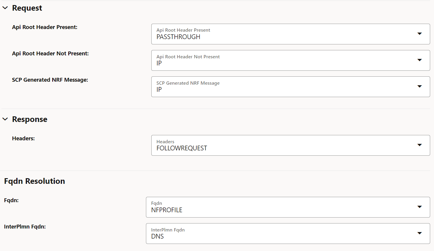
Figure 4-12 Editing Egress Host Preference
- Set Enabled to true.
By default, this option is set to false.
- In the Feature Specific Config section, to configure the host
preference, set the following fields as described in the following table:
Table 4-1 Host Preference
Field Name Description Api Root Header Present This parameter indicates the host preference (":authority" header) for egress message requests if the 3gpp-Sbi-Target-apiRoot header is present in the ingress message request. You can set this field to PASSTHROUGH to use the same type of host in egress message requests as received through ingress message requests.
Default value: PASSTHROUGH
Range: IP, FQDN, or PASSTHROUGH
Api Root Header Not Present This parameter indicates the host preference (":authority" header) for egress message requests if the 3gpp-Sbi-Target-apiRoot header is absent in ingress message requests. Default value: IP
Range: IP or FQDN
SCP Generated NRF Message This parameter indicates the host preference (":authority" header) for SCP generated NRF messages. Default value: IP
Range: IP or FQDN
Fqdn This parameter indicates the resolution preference of egress message requests host FQDN if present. Default value: NFPROFILE
Range: DNS or NFPROFILE
InterPlmn Fqdn This parameter indicates the resolution preference of egress message requests inter-plmn FQDN if present. Default value: DNS
Range: DNS or NFPROFILE
- Click Save.
4.2.1.10 Configuring CCA Header Validation
Perform the following option to configure CCA Header validation.
- In the left navigation pane, click the CCA Header Validation tab.
- In the CCA Header Validation section, click
Edit.
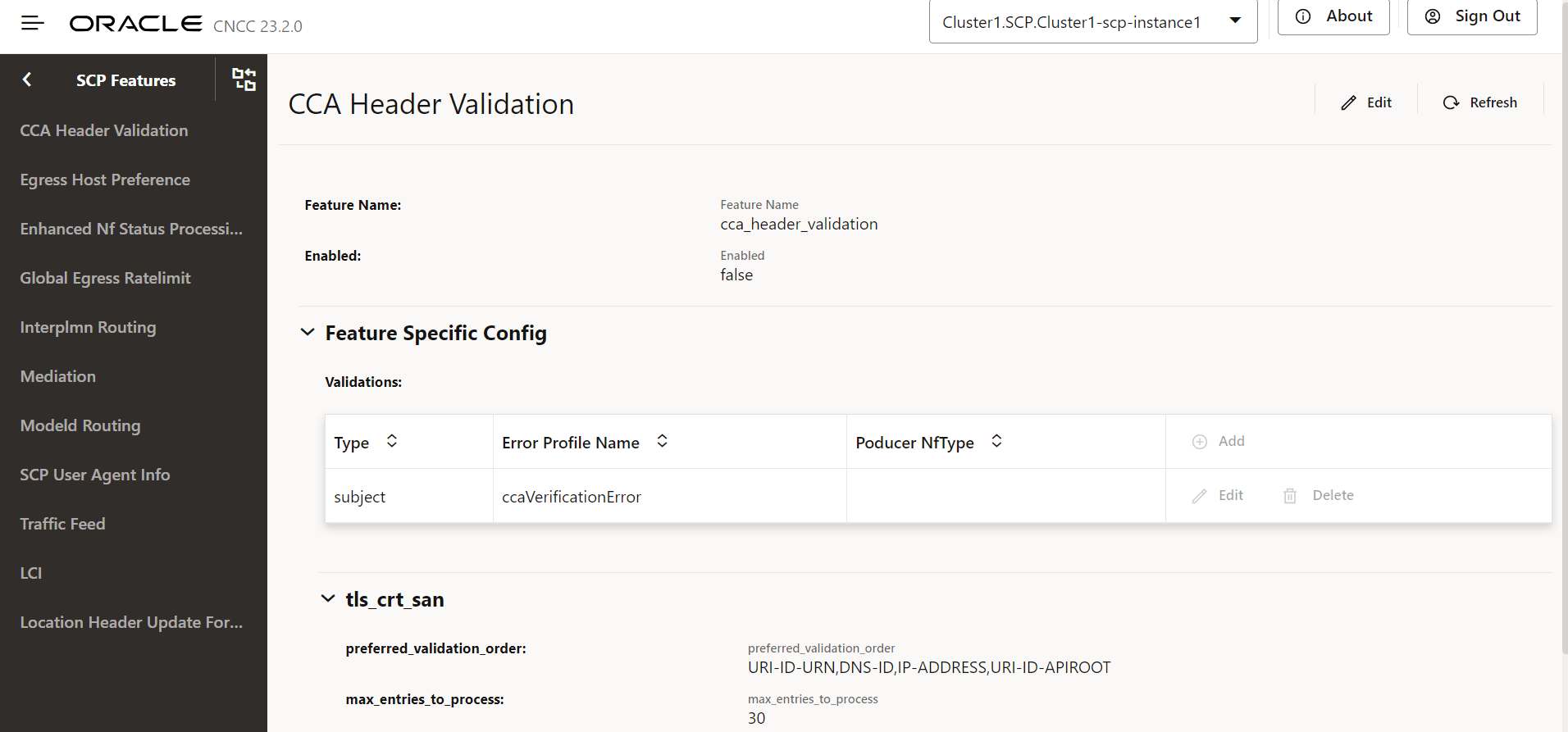
Figure 4-13 Edit CCA Header Validation
- Set Enabled to true.
By default, this option is set to false.
- In the Feature Specific Config section, to configure the
validations, set the following fields as described in the following table:
Table 4-2 Validations
Field Name Description Type Type of validation: - headerPresence: SCP checks the presence of
the 3gpp-Sbi-Client-Credentials header in the ingress
request.
- Validation will pass if the header is present.
- Validation will fail if the header is not present.
- subject: SCP checks the NF instance ID from
the "sub" parameter in the 3gpp-Sbi-Client-Credentials
header with the NF instance ID from the list of SANs in
the client's TLS certificate. SANs directly have the NF
Instance Id or the client's other identity, like the
FQDN or IP address, which will be used to get the NF
Instance Id. If the 3gpp-Sbi-Client-Credentials header
is not present, then this validation will not be
performed.
- Validation will pass if the NF instance ID from the "sub" parameter matches the NF instance ID from the SAN.
- Validation will fail if the NF instance ID from the "sub" parameter doesn't match the NF instance ID from the SAN.
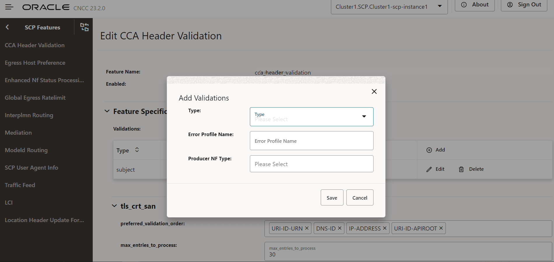
Error Profile Name The error profile name is used to generate an error response if the corresponding validation fails. Error profiles can be configured using the REST API: /ocscp/scpc-configuration/{version}/errorProfileConfig.Product NF Type Default Value: Null preferred_validation_order An order format-wise from which the SCP picks SAN from the client's TLS certificate for verification of the "subject" type of validation. Note: Applicable only when validation type "subject" is selected.
max_entries_to_process Maximum number of SANs from the client's TLS certificate that SCP picks for validation. Note: Applicable only when validation type "subject" is selected.
- headerPresence: SCP checks the presence of
the 3gpp-Sbi-Client-Credentials header in the ingress
request.
- Click Add to add validations:
Figure 4-14 Add Validations
- Click Save.
4.2.1.11 Configuring Location Header Update for Host Mismatch
Perform the following the procedure to configure location header update for host mismatch.
- In the left navigation pane, click the Location Header Update For Host Mismatch tab.
- In the Location Header Update For Host Mismatch
section, click Edit.
Figure 4-15 Edit Location Header Update For Host Mismatch
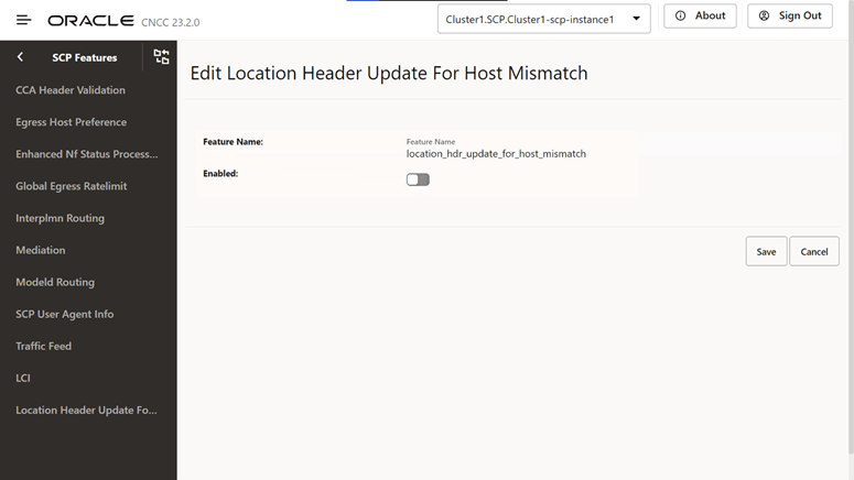
- Set Enabled to true.
By default, this option is set to false.
- Click Save.
4.2.1.12 Configuring Support for OAuth2.0
Perform the following the procedure to configure support for OAuth2.0.
- In the left navigation pane, click the OAuth2 Support tab.
- In the OAuth2 Support section, click
Edit.
Figure 4-16 OAuth2 Support
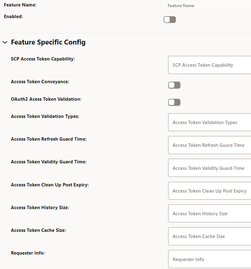
- Set Enabled to true.
By default, this option is set to false.
- In the Feature Specific Config section, complete the
following configurations:
Table 4-3 Configure Access Token
Field Name Description SCP Access Token Capability This field indicates Access token support for the listed indirect communication modes at SCP. (ENUM). Possible values: [INDIRECT_COM_WITH_DELEG_DISC, INDIRECT_COM_WITHOUT_DELEG_DISC]- INDIRECT_COM_WITH_DELEG_DISC: SCP initiates access token request toward NRF in delegated discovery service request.
- INDIRECT_COM_WITHOUT_DELEG_DISC: SCP is expected to forward the service request with or without access token as per configuration at SCP. SCP is not expected to initiate access token request toward NRF.
Access Token Conveyance This field conveys acquired access token in the "3gpp-Sbi-Access-Token" header in service response to consumer NFs.- Default value: true
- Range: true or false
OAuth2 Access Token Validation This field enables or disables validation of OAuth2 access token from consumer NFs. - Default value: Disabled
- Range: Disabled or Enabled
Access Token Validation Types This field configures the list of required validation types in the network. - Default value: empty as default
- Range: Disabled or Enabled
Access Token Refresh Guard Time This field initiates proactive refresh of cached access token when the configured time expires. The proactive refresh occurs if the relevant SBI messages are in exchange. - Default value: 60000ms
- Range: 100ms - 300000ms
Access Token Validity Guard Time This field indicates the time before the access token expiry when SCP considers not to use the existing access token and obtains new access token in the service request forwarded to producer NFs. - Default value: 30000ms
- Range: 100ms - 300000ms
Access Token Clean Up Post Expiry This field indicates the duration to purge the token from cache. - Default value: 900000ms
- Range: 0ms - 3600000ms
Access Token History Size This field indicates the number of access tokens signature history to identify whether the access token initiated by SCP or not. - Default value: 10 records
- Range: 0 - 20 records
Access Token Cache Size This field indicates the number of access tokens that can be cached in SCP. - Default value: 50000 records
- Range: 5000 - 100000 records
Requester Info This field indicates access token requester (consumer NF) Info to generate the access token request. - Prioritized list of default values:
- DISCOVERY-HEADERS
- CCA-HEADER
- USER-AGENT-HEADER
Cache Enabled This option enables or disables caching of access tokens. - Default value: true
- Range: true or false
- Click Save.
4.2.1.13 Configuring SCP Health Check API
Perform the following the procedure to configure SCP health check API.
- In the left navigation pane, click the Health Check tab.
- In the Health Check section, click
Edit.
Figure 4-17 Health Check
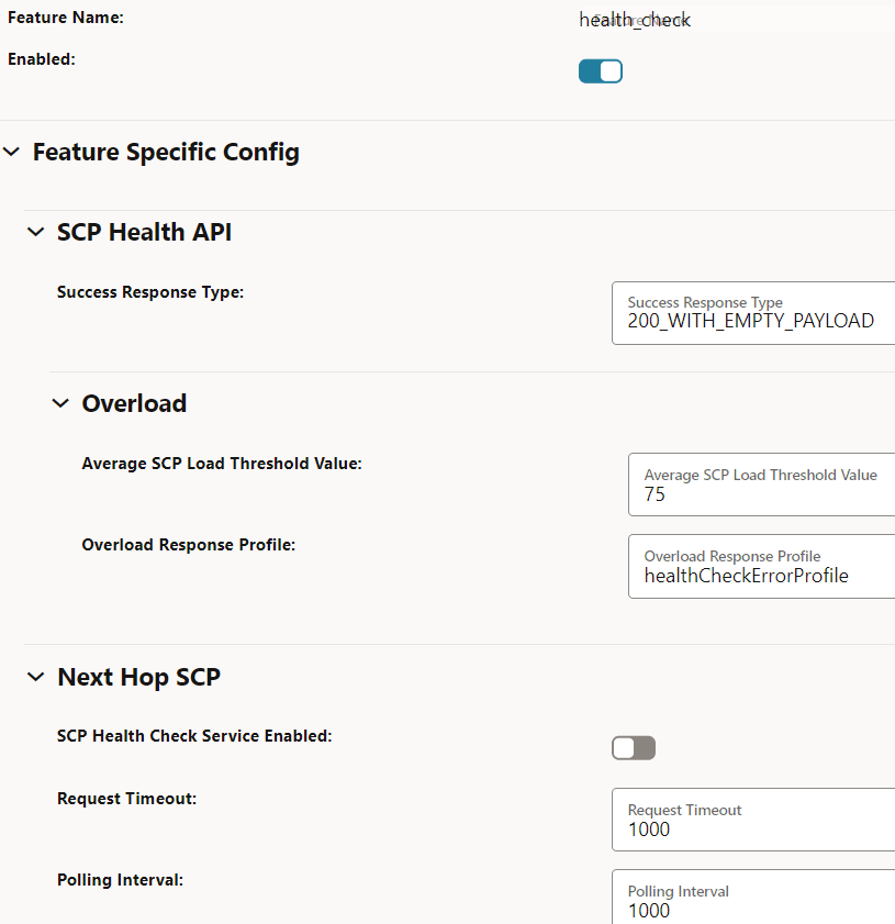
- Ensure that Enabled is set to true.
This is the default configuration.
- In the Feature Specific Config section, you can modify the
following configurations:
Table 4-4 Configure Health Check API
Field Name Description Success Response Type This field indicates successful responses for a healthy SCP. - Default value: 200StatusCodeAndEmptyPayload
- Range: 200WithPayLoad, 200WithEmptyPayload, and 204WithNoContent
Average SCP Load Threshold Value This field provides the overall average SCP load threshold value. - Default value: 75%
- Range: 75% - 90%
Overload Response Profile This field indicates the error profile configuration for the health query response in the exception conditions. - Default value: healthCheckErrorProfile. For more information about this option, see "Configuring Error Profiles" in Oracle Communications Cloud Native Core, Service Communication Proxy REST Specification Guide.
SCP Health Check Service Enabled This option enables or disables the SCP health check API feature in inter-scp scenarios. - Default value: false
- Range: true or false
Request Timeout This field indicates the timer to monitor the waiting time for health check response in inter-scp scenarios. - Default value: 1000ms
- Range: 300ms -60000ms
Polling Interval This field indicates the duration to control the periodicity of health check requests in inter-scp scenarios. - Default value: 1000ms
- Range: 300ms -60000ms
Consecutive Error Response This field indicates the total number of consecutive failure responses that leads to failover in inter-scp scenarios. - Default value: 3
- Range: 1 - 20
Consecutive Success Response This field indicates the total number of consecutive successful responses that leads to fallback in inter-scp scenarios. - Default value: 3
- Range: 1 - 20
- Click Save.
4.2.1.14 NRF Configuration using DNS SRV Resolution
Perform the following procedure to NRF configuration using DNS SRV resolution.
- In the left navigation pane, click the NRF Bootstrap Info tab.
- In the NRF Bootstrap Info section, click
Edit.
Figure 4-18 Edit NRF Bootstrap Info
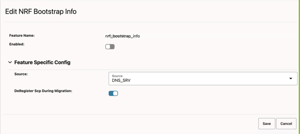
- Set Enabled to true.
By default, this option is set to false.
- In the Feature Specific Config section, enter the following
input for the following configurations:
Table 4-5 Configure NRF Source Configuration
Field Name Description Source This field is used to select whether the NRF Configuration Using DNS SRV Resolution feature should be enabled or disabled. SCP will enable the feature if the source is DNS_SRV. The default value is DNS_SRV.
deRegisterScpDuringMigration In the migration from static to DNS SRV task, if static and DNS SRV NRF configurations are the same, then this parameter will be used to deregister SCP with the old or static NRFset.- Default value: false
- Range: true or false
- Click Save.
4.2.1.15 Configuring Overload Control Based on the Overload Control Information Header
Perform the following procedure to configure overload control based on the overload control information header.
- From the SCP Features list, click the OCI tab.
- On the OCI page, click the Edit icon.
Figure 4-19 Edit OCI

- In the Edit OCI section, set
Enabled to true.
By default, this option is set to false.
Figure 4-20 Enabling OCI
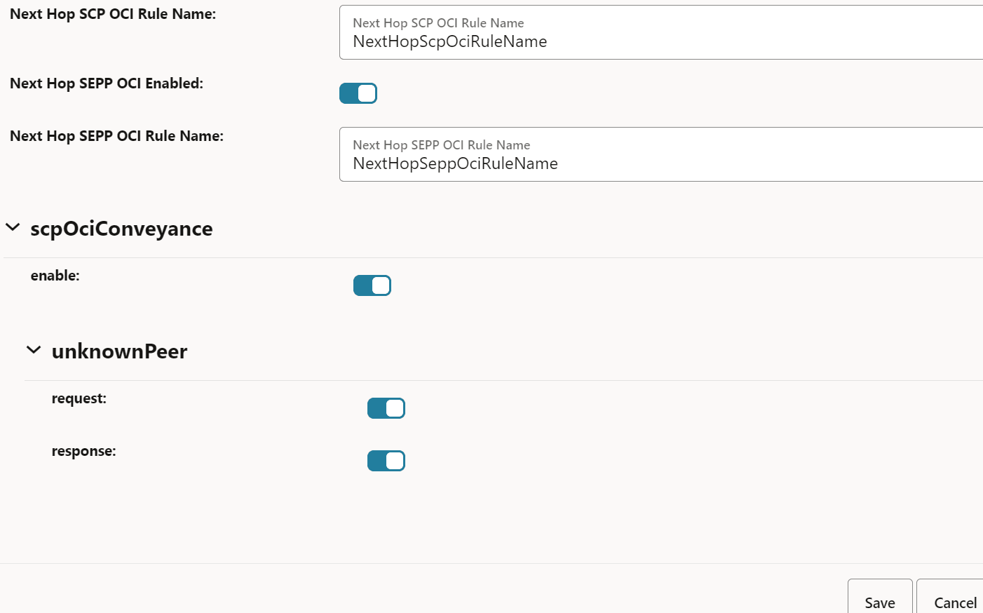
- To configure OCI, in the Feature Specific Config
section, set the following fields:
Table 4-6 Configure OCI
Field Name Description olcHSupportInd This option indicates that SCP supports the Overload Control Information (OCI) feature based on the 3gpp-Sbi-Oci header. By default, this option is enabled.
SCP OCI Conveyance Interval This field indicates the interval for reporting SCP OCI to peer NFs. For every interval until the validity period, the last sent OCI is reported to peer NF irrespective of any change to SCP OCI. Sending SCP OCI periodically ensures that the peer NF has not missed an earlier reported SCP OCI. The same OCI header as sent on the last OCI threshold change or validity period expiry is sent. - Default value: 2000 milliseconds
- Range: 2000 to 3600000 milliseconds
Note: OCI is sent to peer NFs only if there is a message for that NF.
SCP OCI Recovery Validity Period This field indicates the validity period to send OCI headers to peers when SCP recovers from an overloaded state. SCP sends OCI to peers with reduction metric as 0. - Default value: 3600 seconds
- Range: 5 to 3600 seconds
Next Hop SCP OCI Enabled This option enables or disables the OCI feature between SCP instances and SCP scope OCI. By default, this option is enabled.
Next Hop SCP OCI Rule Name If the Next Hop SCP OCI Enabled option is enabled, the OCI feature enforcement is done based on the ociConfigRule REST API configuration with the name provided as the value for this option. By default, this value is NextHopScpOciRuleName.
Next Hop SEPP OCI Enabled This option enables or disables OCI enforcement between SCP and SEPP interfaces and SEPP scope OCI. By default, this option is enabled.
Next Hop SEPP OCI Rule Name If the Next Hop SEPP OCI Rule Name option is enabled, the OCI feature enforcement is done based on the ociConfigRule REST API configuration with the name provided as the value for this option. By default, this value is NextHopSeppOciRuleName.
scpOciConveyance If this option is set to true, SCP starts conveying the 3gpp-Sbi-Oci header based on self-overload information. By default, this option is enabled.
unknownPeer
- request
If this field is set to true, SCP starts conveying the 3gpp-Sbi-Oci header based on self-overload information to requests to unknown peers. For unknown peers, identification of peer NFs is done based on the message request's FQDN. By default, this option is enabled.
unknownPeer
- response
If this option is set to true, SCP starts conveying the 3gpp-Sbi-Oci header based on self-overload information to responses to unknown peers. If this parameter is set to true, SCP adds self-OCI header in every response message. By default, this option is disabled.
- Click Save.
4.2.1.16 Configuring Enhanced NFProfile Processing
- In the left navigation pane, click the Ignore Unknown Nf
Service tab.
The Ignore Unknown Nf Service page appears.
Figure 4-21 Ignore Unknown Nf Service

- On the Ignore Unknown Nf Service page, click the Edit icon.
- In the Edit Ignore Unknown Nf Service
section, set Enabled to true.
By default, this option is set to false.
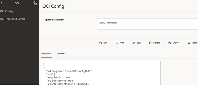
4.2.2 Configuring OCI
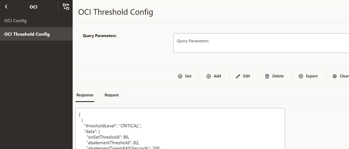
4.2.3 Configuring OCI Threshold Levels
4.2.4 Viewing cnDBTier APIs in CNC Console
Note:
The following cnDBTier APIs are read only.- From the left navigation pane, click the SCP tab, and then click the cnDBTier tab.
- Click the Backup List to view the list of
completed backups along with Backup ID, Backup size, and Creation Timestamp.
The Backup List screen is displayed.
Table 4-9 Backup List
Fields Description Backup Details This field displays information such as backup Id, backup size, and backup creation timestamp. Site Name This field displays the name of the current site to which SCP is connected. Backup Id This field displays the ID of the stored backup. Backup Size (bytes) This field displays the size of the stored backup. Creation TimeStamp This field displays the time recorded when the backup was stored. - Click the cnDBTier Version to view the
version.
Table 4-10 cnDBTier Version Attributes
Fields Description cnDBTier Version This field displays the cnDBTier version. NDB Version This field displays the network database (NDB) version. - Click the Database Statistics Report to view
the available database.
Table 4-11 Database Statistics Report
Fields Description Database Count This field displays the number of available database. Database Tables Count This field displays the available database names and their table count. Database Name This field displays the database name. Table Count This field displays the table count for each database. Database Table Rows Count This field displays the table rows present in each table. Click on View icon available next to the database name to view the View Database Table Rows Count screen.Table 4-12 View Database Table Rows Count
Fields Description Database Name This field displays the database name. Tables This field displays the table names and the corresponding rows in each table. Table Name This field displays the table name. Row Count This field displays the table rows present in each table. - Click the Geo Replication Status to view the
local site and remote site name to which SCP is connected.
Table 4-13 GeoReplication Status
Fields Description Local Site Name This field displays the local site name to which SCP is connected. Remote Site Name This field displays the remote site name. Replication Status This field displays the replication status with corresponding sites. Seconds Behind Remote Site This field displays the number of seconds that the last record read by the local site is behind the latest record written by the remote site for all the replication groups. - Click the View icon in the
Actions menu to view the View Geo
Replication Status screen.
Table 4-14 Geo Replication Status
Fields Description Replication Group Delay This field displays the number of seconds that the last record read by the local site is behind the latest record written by the remote site for individual replication groups. Replication Channel Group Id This field displays the ID of the replication channel group. - Click the View icon to view the
Replication Group Delay attributes.
Table 4-15 View Replication Group Delay
Fields Description Channel Details This field displays the channel details such as Remote Replication IP and Role. Remote Replication IP This field displays the IP of the remote replication channel. Role This field displays the role of the replication channel IP.
- Click the View icon in the
Actions menu to view the View Geo
Replication Status screen.
- Click the HeartBeat Status to view the
connectivity between local site and remote site name to which SCP is
connected.
Table 4-16 HeartBeat Status Details
Fields Description Site Name This field displays the name of the current site to which SCP is connected. HeartBeat Details This field displays information such as the remote site name, heartbeat status, heartbeat lag, and replication channel group id. Remote Site Name This field displays the remote site name. Heartbeat Status This field displays the connectivity status with corresponding sites. Heartbeat Lag This field displays the lag or latency in seconds it took to syncronize between sites. Replication Channel Group Id This field displays the ID of the replication channel group. - Click the Local Cluster Status to view the
local cluster status for the current site:
Table 4-17 Local Cluster Status
Fields Description Site Name This field displays the name of the current site to which SCP is connected. Cluster Status This field displays the local cluster status for the current site. - Click the On Demand Backup to create a new
backup and view the status of initiated on-demand backups.
Table 4-18 On Demand Backup Details
Fields Description Site Name This field displays the name of the current site to which SCP is connected. DR Status This field displays the status of DR. Backup Id This field displays the ID of the stored backup. Backup Status This field displays the status of backup. Remote Transfer Status The field displays the status of remote transfer. Initiate Backup The field displays whether the backup is initiated or not. - Click the Edit icon.
The Edit On Demand Backup screen appears.
Note:
The Edit mode is available only for Initiate Backup. - Enable the Initiate Backup option click
Save.
A confirmation message "Save successfully" appears.
- Click theCancel to navigate back to the On Demand Backup screen.
- Click the Refresh to reload the On Demand Backup screen.
- Click the Edit icon.
4.2.5 Configuring NRF SRV
- From the left navigation pane, navigate to SCP and click the NRF SRV Configuration tab.
- In the NRF SRV
FQDN section, click the
Add button to create the new
NRF SRV configuration for the given NRF SRV FQDN.
You can configure the NRF configurations at run time, and this NRF SRV FQDN shall be mapped to target NRF FQDNs. SCP uses this NRF SRV FQDN to query the DNS SRV server to get the actual target NRF FQDNs. NRF SRV FQDN
Figure 4-24 Add NRF SRV Configuration
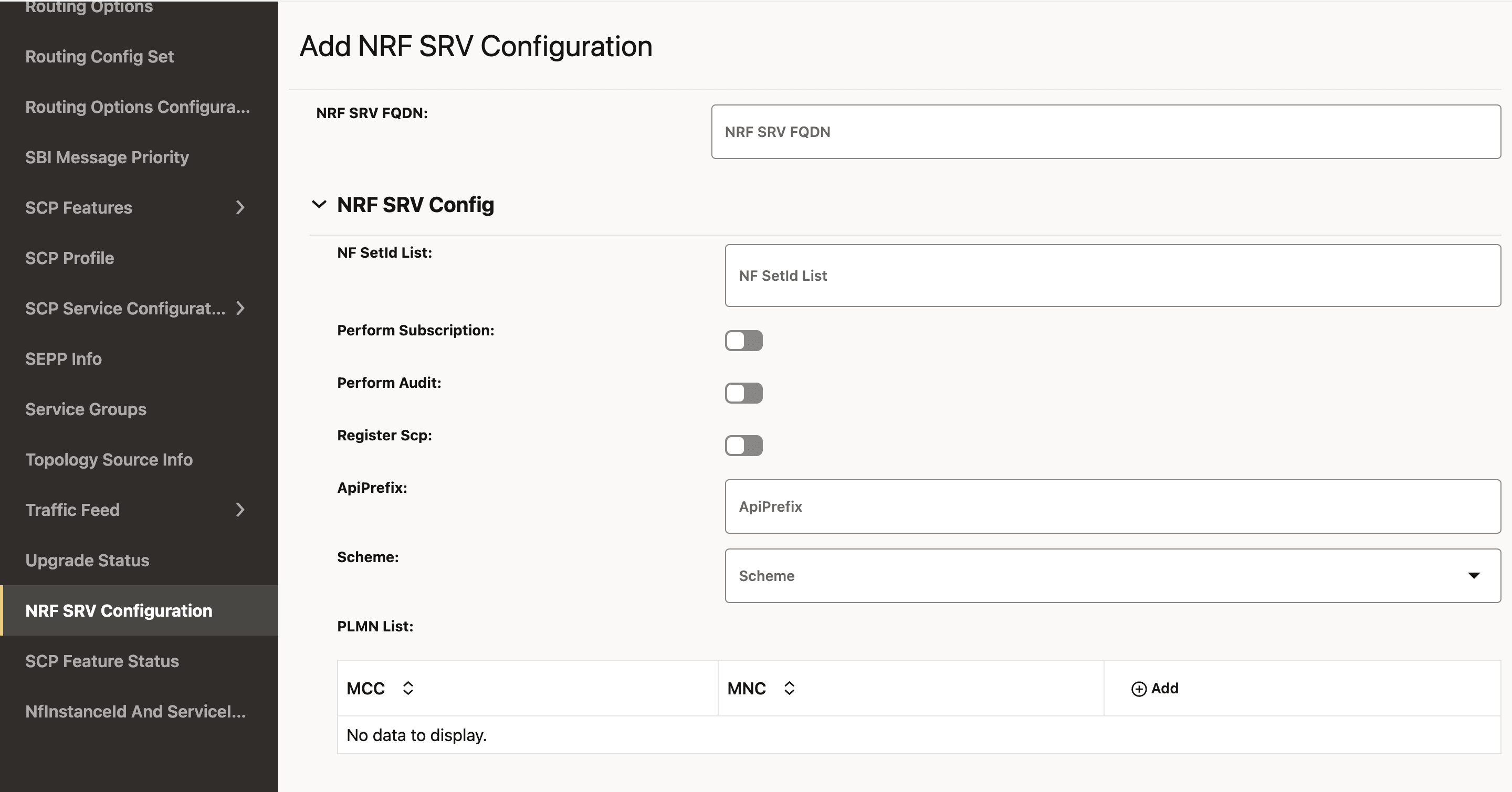
- To configure the NRF SRV, enter the input for the
following fields:
Table 4-19 NRF SRV Configuration
Field Name Description NF SetId List This is the SetId list for this NRF SRV configuration. You can configure multiple nfSetIds, but the NRF profile and rule creation will only take into account the nfSetId from the 0th index.
This setId must be unique for each NRF SRV configuration; that is, this setId must not be present in any other NRF SRV configuration.
Perform Subscription This field allows to decide whether NRF from this NRF SRV should be used for a subscription or not. The possible values are true or false.
Perform Audit This field allows to decide whether NRF from this NRF SRV should be used for a audit or not. The possible values are true or false.
Register SCP This field allows to decide whether to register SCP with the NRF from the NRF Set. The possible values are true or false.
Scheme This field is used for the URI Scheme. The supported value is http/https. PLMN List This field indicates the list of NRFs serving Public Land Mobile Network (PLMN). A PLMN has a unique PLMN code, which consists of a MCC (Mobile Country Code) and an MNC (Mobile Network Code).
Click the Add button to add MCC and MNC, respectively.
Versions This field lists the NFServiceVersion. Configuring multiple API versions is permissible, but at least one entry in the version list must have its apiVersionInUri set to "v1." This is because SCP currently utilizes "v1" for its self-generated requests towards NRF.
- Click the Add button to add NFServiceVersion.
- The supported value of apiVersionInUri is v1/v2.
- The apiFullVersion should be in format x.y.z., for example, 1.0.0.
apiPrefix This field is used in the URI while communicating with NRF. serviceNames Indicates the service name of the NRF SRV configuration.
The nnrf-nfm and nnrf-disc are mandatory for NRF SRV configurations.
The supported value is nnrf-nfm/nnrf-disc/nnrf-oauth2.isInterPlmnFqdn This field allows you to choose whether or not to map the NRF from this NRF SRV resolution to the InterPlmn Fqdn. - In the NRF SRV FQDN section, click the Edit icon to update the existing NRF SRV configuration.
- Click Save.
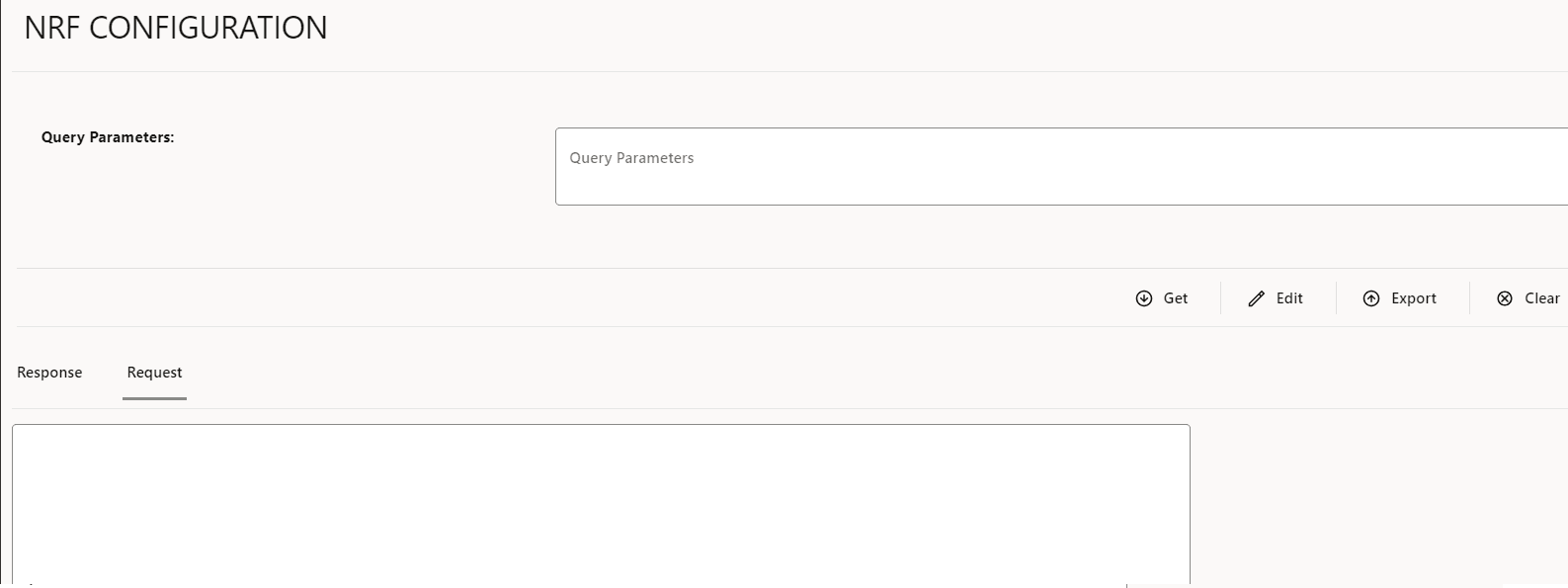
4.2.6 Configuring NRF
4.2.7 Configuring Upgrade and Rollback Event
4.2.8 OAuth2.0 Configurations
You must log in to the CNC Console while performing the procedures described in the subsequent subsections. Using these procedures, you can perform the followings tasks:
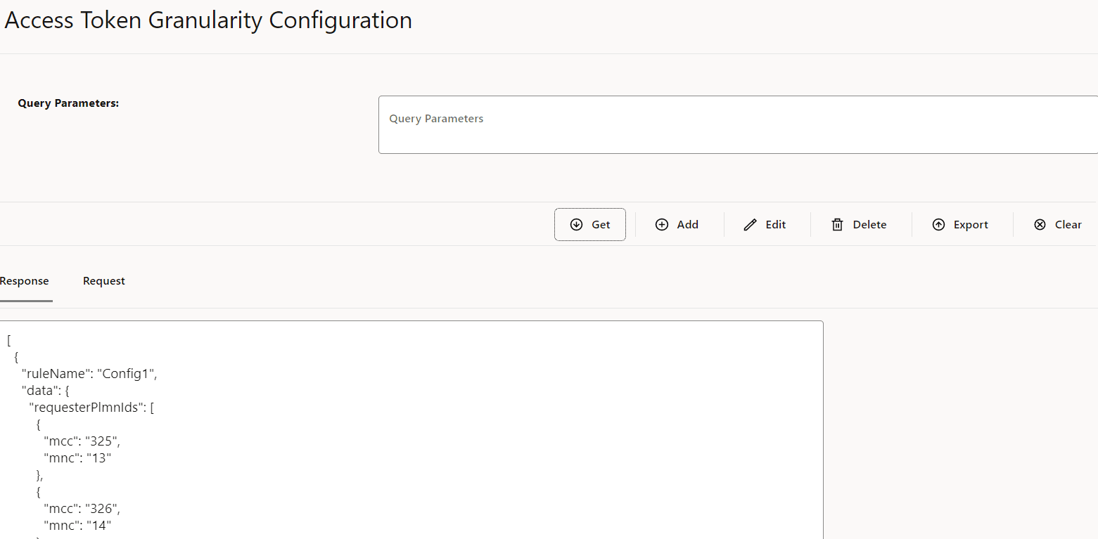
- Configure access token granularity
- Configure OAuth2.0 Local PLMN
4.2.9 Configuring Error Profile
Perform the following procedure to configure different error profiles, which can be used to build "ProblemDetails" sent in the response body to the consumer.
- From the left navigation pane, click the SCP
tab, and then click the Error Profile tab.
Figure 4-30 Error Profile

- Click Edit icon from the Actions column for the error profiles
that must be modified. The Edit Error Profile screen appears.
Figure 4-31 Edit Error Profile

- If the required cause is not available in the Cause
drop-down list, select CUSTOM to customize the cause:
Figure 4-32 Customize the Cause
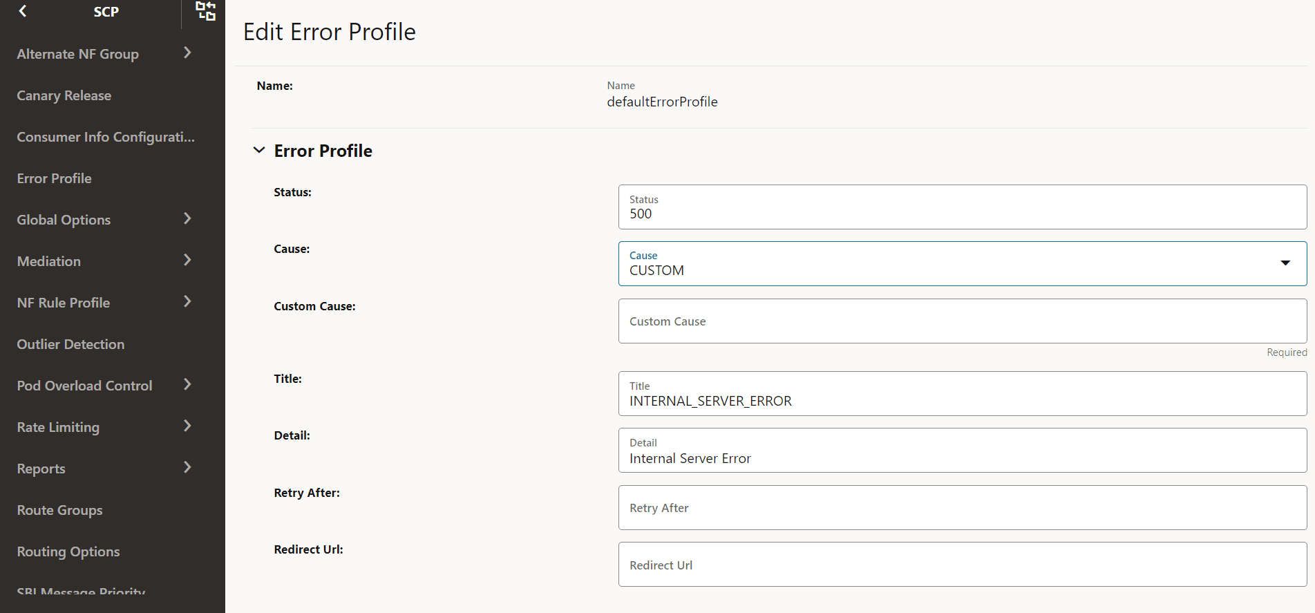
- Make the required modifications for the following parameters:
Table 4-25 Edit Error Profile
Field Description Status HTTP Status Code Cause The list of error causes that are specific to the occurrence of the problem. Custom Cause User defined custom cause. This field will be used only if cause field value is set to "CUSTOM". Title If this field is null, a standard HTTP status code description is added. Detail If present, the same data is used; otherwise, the application can add it optionally. Retry After Indicates the number of seconds after client should retry. Redirect URL Indicates the AbsoluteURL of the resource to which the message is redirected to. For information about configuring error profiles, see "Configuring Error Profile" in Oracle Communications Cloud Native Core, Service Communication Proxy REST Specification Guide.
- Click Save.
4.2.10 Configuring Canary Release
Following is the procedure to configure Canary Release parameters:
- From the left navigation menu, navigate to SCP and then select Canary Release.
- Click Edit from the
Actions column for the required service that must be modified. The Edit Canary Release
Screen appears.
Figure 4-33 Canary Release

- Make the required modifications for the following parameters:
- Canary Release Flag: Enable/Disable the flag using toggle.
- API Release Version: Provide the release version of the API.
- Canary Traffic: Set the value for the traffic that should be distributed to Canary Release.
For more information about the configuration parameters, see Oracle Communications Cloud Native Core, Service Communication Proxy REST Specification Guide.Figure 4-34 Edit Canary Release

- Click Save.
- Click Refresh to view the updated values on the screen.
4.2.11 Configuring Global Options
Perform the following procedure to configure global options.
Logging Config
- From the left navigation menu, navigate to SCP and select Global Options.
- Select Logging Config.
- Click Edit from the top right side to edit or update Logging
Config parameters.
Figure 4-35 Logging Config
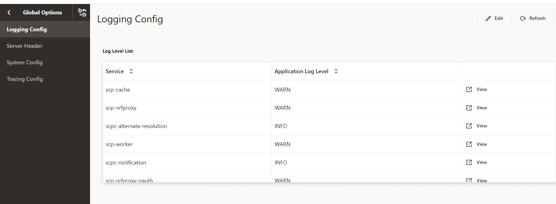
- Select Service Type from the drop-down list to select any
one of the following service type:
- scpc-audit
- scpc-alternate-resolution
- scpc-subscription
- scpc-configuration
- scpc-notification
- scp-worker
- scp-cache
- scp-nrfproxy
- Select the Application Log Level from the drop-down list to
set the constraints of the log.
The description of each logging level is as follows:
Table 4-26 Logging Level
Logging Level Description DEBUG A log level used for events considered to be useful during software debugging when more granular information is required. INFO The standard log level indicating that something happened, the application entered a certain state, and so on. WARN Indicates that something unexpected happened in the application, a problem, or a situation that might disturb one of the processes. But that doesn’t mean that the application has failed. The WARN level should be used in situations that are unexpected, but the code can continue the work. ERROR The log level that should be used when the application reaches an issue preventing one or more functionalities from properly functioning. - Click Add provided under Package Log Level section to specify the name of the package and its log level.
- Click Save.
Note:
You can also Edit and Delete the packages under Package Log Level.
System Config
Perform the following procedure to edit the system config parameters.
- From the left navigation menu, navigate to SCP and select Global Options.
- Select System Config.
- Click Edit from the top right side to edit or update
System Config parameters.
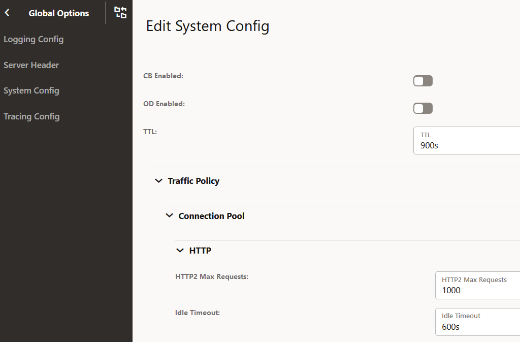
Figure 4-36 System Config
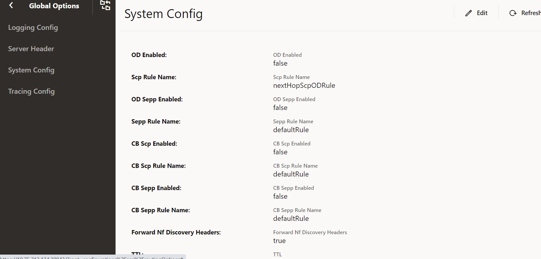
- Update the attributes as described in "Configuring
SystemOptions" in Oracle Communications Cloud Native Core, Service Communication Proxy REST
Specification Guide.
Note:
Ensure that Forward Nf Discovery Headers is set to true to forward discovery headers to Nexthop SCP as part of the Model D Indirect 5G SBI Communication feature.The default value is true.
- Click Save after performing the modifications.
Tracing Config
Perform the following procedure to edit tracing config options.
- From the left navigation menu, navigate to SCP and select Global Options.
- Select Tracing Config.
- Click Edit from the top right side to edit or update
Tracing Config options.
Figure 4-37 Tracing Config

- Set the following switches as required:
- Tracing Enabled
- Message JSON Body Enabled
For information about tracing parameters, see "Updating HELM Configurable Parameters with REST APIs" in Oracle Communications Cloud Native Core, Service Communication Proxy REST Specification Guide.
- Click Save after performing the modifications.
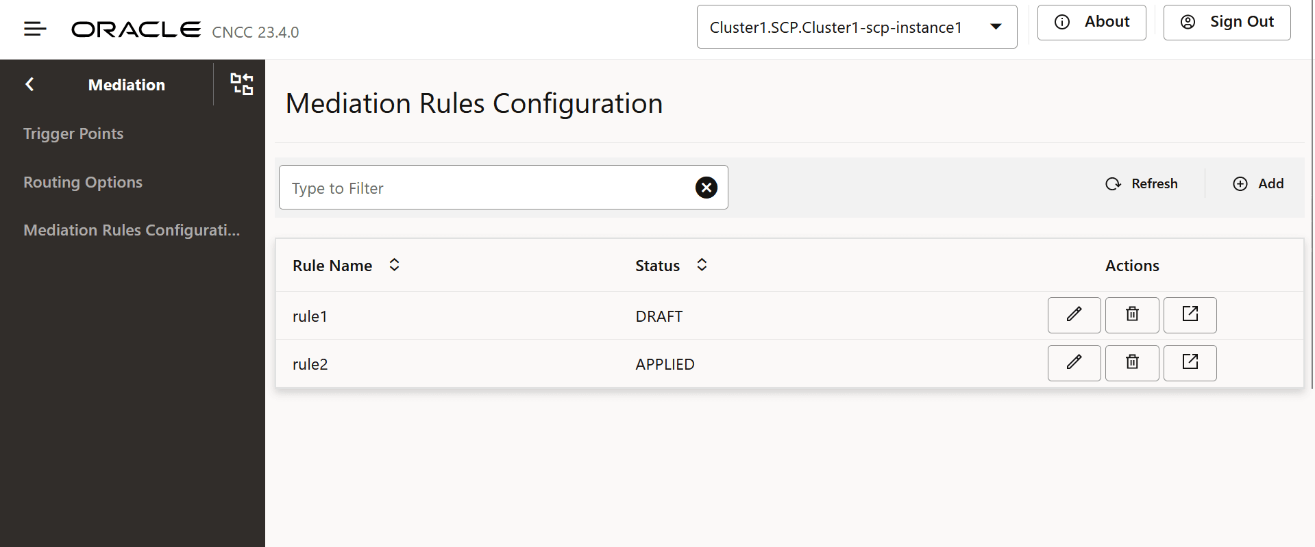
4.2.12 Configuring Mediation
- From the left navigation pane, click the SCP tab, and
then click the Mediation tab.
Trigger Points and Routing Options tabs appear.
- To configure trigger points for defining the filter criteria for a message, in the left navigation pane, click the Trigger Points tab.
- In the Trigger Points section,
click Add and configure the fields as described in the
following table:
Table 4-27 Trigger Points Field Description
Field Description Group Id Indicates the group ID for which mediation configuration is required. The Mediation configuration for a specific group is applicable to the mediation requests or responses received only from the same group. The HTTP Mediation service consumer NFs, which requires the same mediation rules, can be grouped together using this group ID.
Rule Name Indicates the unique rule name for each mediation configuration that is consdiered as a primary key. Service Name Indicates the service of NFType for which mediation configuration is required. NF Type Indicates the NFType for which mediation configuration is required. Http Methods Indicates the HTTP methods such as GET, POST, PUT, PATCH, DELETE,and OPTION. Mediation Trigger Points Indiactes the list of trigger points to be enabled if matches one or more of the following: requestIngress, requestEgress, responseIngress, and responseEgress. Match Indicates the list of match blocks to be satisfied for the rule to be activated. The list of match blocks have OR semantics.
Minimum number of blocks = 1
Maximum number of blocks = 20
Add Adds HTTP headers and JSON body criteria - In the Match section, click
Add.
The Add Match dialog box appears.
Figure 4-38 Add Match
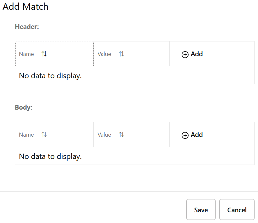
- In the Header section, click
Add to set the header details as follows:
- Name: Enter a name for the header.
- Value: Enter a value of the header.
- Match Type: Select a range type from the Match Type drop-down list.
- In the Range section, if the header type has a numeric value, enter the range of that value in Start and End fields.
- Click one of the following buttons:
- Remove: To discard the changes made to the Range section.
- Save: To save the changes.
- In the Body section, click
Add Body to set the JSON body details as follows:
- Name: Enter a name for the body.
- Value: Enter a value for the header.
- Match Type: Select a range type from the Match Type drop-down list.
- In the Range section, if the header type has a numeric value, enter the range of that value in Start and End fields.
- Click one of the following buttons:
- Remove: To discard the changes made to the Range section.
- Save: To save the changes.
- Cancel: To reset all the fields.
4.2.13 Configuring NF Rule Profile
- From the left navigation, navigate to SCP, and then click NF Rule Profile.
- In the NF Rule Profile section, click
Add.
Figure 4-41 Add NF Rule Profile

- Add the following parameters for all the NF Info:
- Group Id: Identity of the NF info.
- Routing Indicators: List of Routing Indicator information.
- Click Add to add the SUPI Ranges.
- Click Save to save the SUPI Ranges.
- Click Remove if you want to remove the NF Info.
- Click Add to add the NF info details.
- Click Save to save the NF Rule Info.
- Click Refresh to view the updated values on the screen.
- To configure a local PLMN, in the PLMN List section, click Add and enter the required Mobile Country Code (MCC) and Mobile Network Code (MNC) values in the displayed fields.
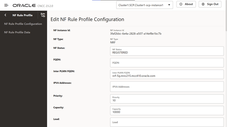
- From the left navigation, navigate to SCP, and then click NF Rule Profile Configuration.
- In the NF Rule Profile Configuration section, click
Edit from Actions. The Edit NF Rule
Profile Configuration screen appears.
Figure 4-42 Edit NF Rule Profile Configuration
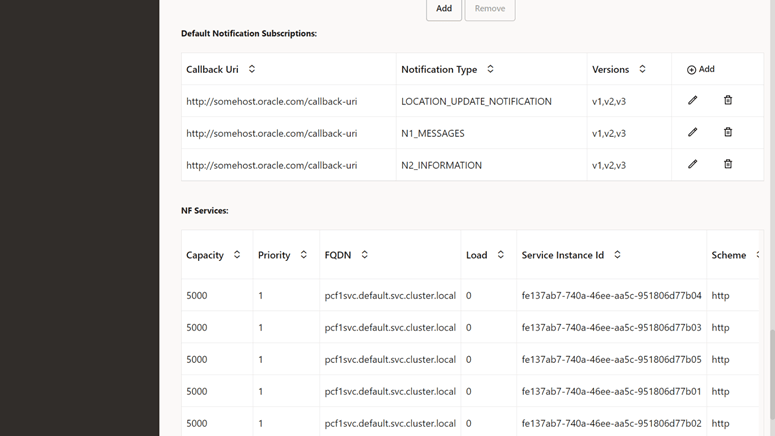
- In the Default Notification Subscription section, click the
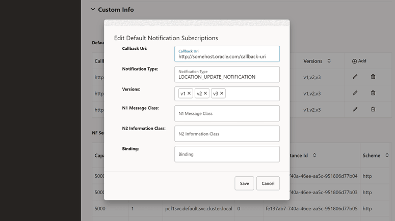
Edit icon for the required callback URI that must
be modified. The Edit Default Notification
Subscription screen appears.
Figure 4-43 Default Notification Subscription
- Make the required modifications for the following fields:
Table 4-31 Default Notification Subscriptions
Attribute name Description Callback Uri This attribute contains a default notification endpoint to be used by a NF service producer towards an NF service consumer that has not explicitly registered a callback URI with the NF service producer, for example, as a result of an implicit subscription. Notification Type Type of notification for which the corresponding callback URI is provided. Versions API versions, for example, v1, are supported for the default notification type. N1 Message Class If the notification type is N1_MESSAGES, this IE must be present to identify the class of N1 messages to be notified. N2 Information Class If the notification type is N2_INFORMATION, this IE must be present to identify the class of N2 information to be notified. Binding When present, this IE contains the value of the binding indication for the default subscription notification, which is the value part of the 3gpp-Sbi-Binding header. See the note for details. Note:
When delivering a notification for a default subscription to a specific NF consumer but the latter is not reachable, a NF service producer uses the binding indication for default subscription to reselect an alternative NF service consumer instance. For example, an AMF notifies corresponding uplink LPP or NRPPa messages through a default subscription to the LMF instance that previously sent downlink LPP or NRPPa messages during a location procedure. If the original LMF instance is not reachable, the AMF selects an alternative LMF instance using the binding indication and delivers the notification to the selected LMF instance.Figure 4-44 Edit Default Notification Subscriptions
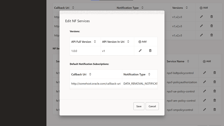
- In the NF service section, click the
Edit icon to edit or add the API full
versions.
Figure 4-45 Edit NF Services
- Click Save to save the NF Rule Info.
- Click Refresh to view the updated values on the screen.
4.2.14 Configuring Routing Options
Perform the following procedure to configure Routing Options parameters.
- From the left navigation menu, navigate to SCP, and then click the Routing Options tab.
- In the Routing
Options section, click Edit from the
Actions column for the required service
that must be modified.
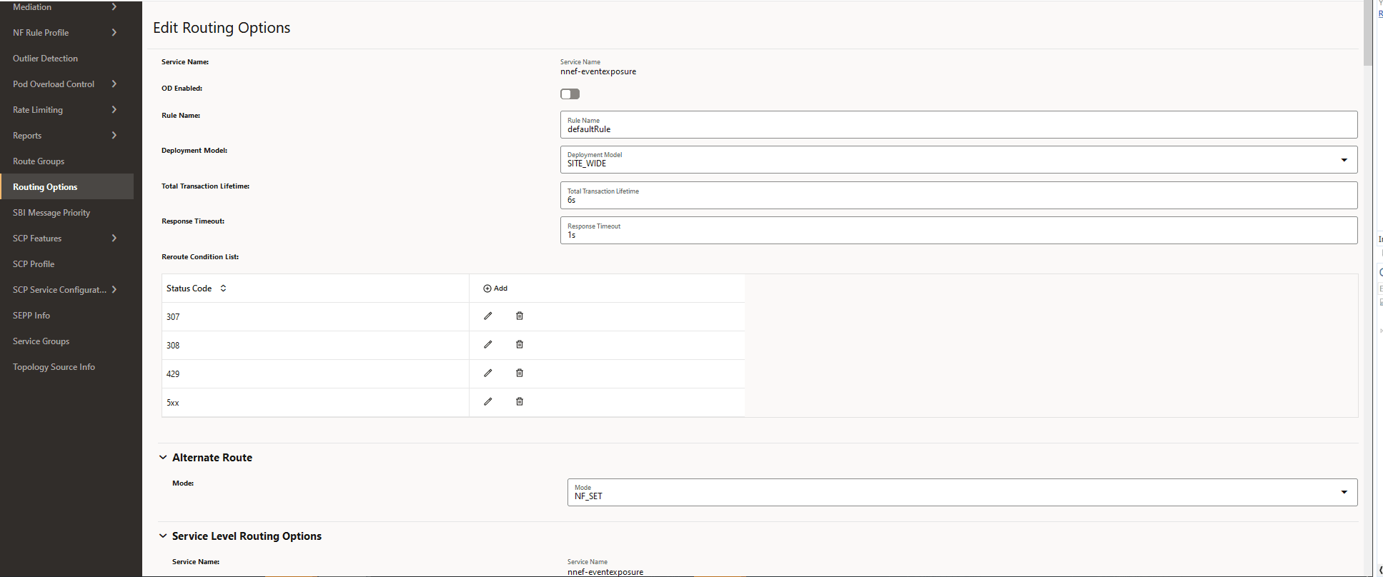
The Edit Routing Options screen appears.
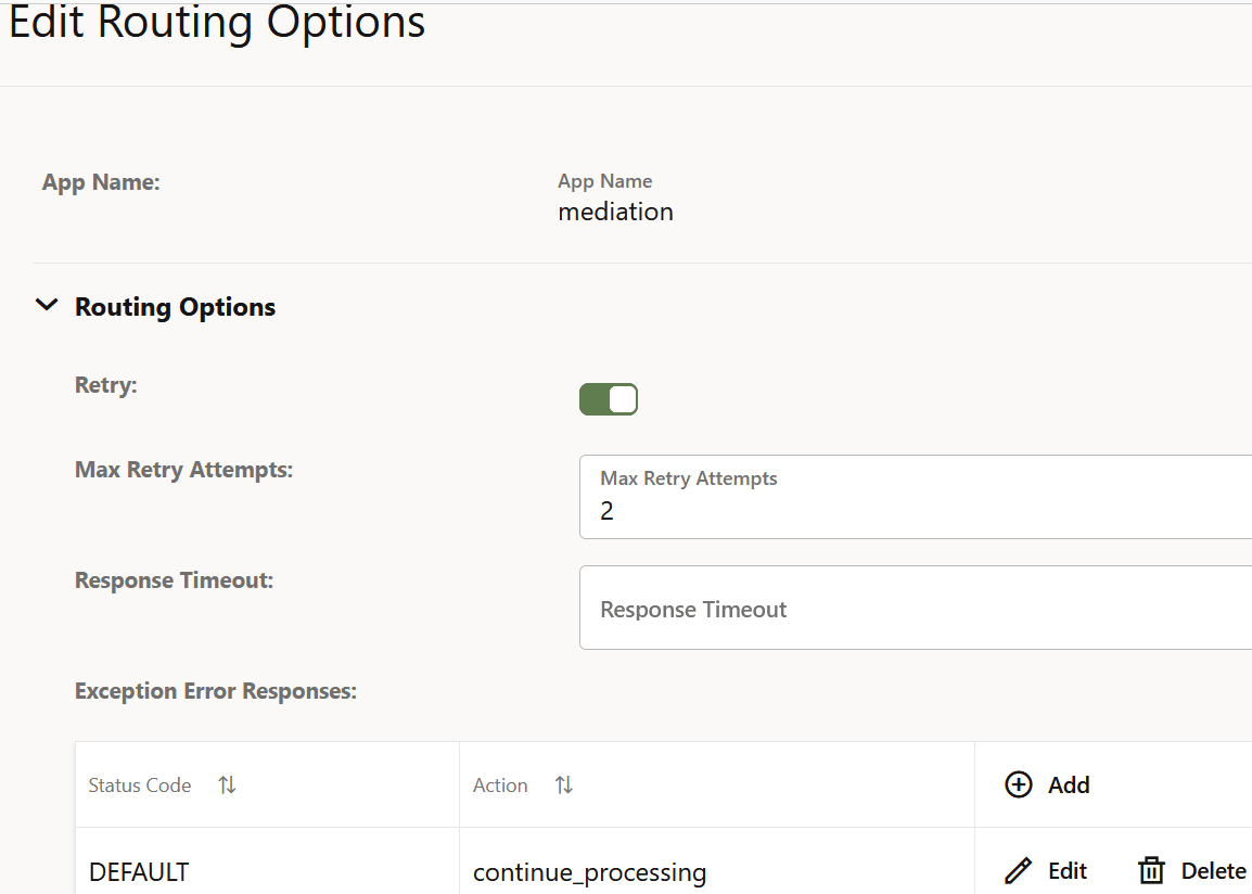
Figure 4-46 Edit Routing Options

Figure 4-47 Load based congestion control enabled

- Enter or modify the required values as described in
"Configuring Routing Options" in Oracle Communications Cloud Native Core, Service Communication Proxy REST
Specification Guide.
Note:
Ensure that the following options are set as required to manage the "3gpp-Sbi-Discovery-preferred-locality" header as part of the Model D Indirect 5G SBI Communication feature:- Assign Preferred Locality
- Override Preferred Locality
- Forward Revised Preferred Locality
- In the Reroute Condition List,
configure the list of error codes for rerouting:
- Click Add to add new status code.
- Click Edit or Delete icon to edit or remove any existing error code from the reroute condition list.
- In the Alternate Route section, set the
Mode of the specific services as required:
- NF_SET: SCP performs alternate routing based on the Model C Indirect 5G SBI Communication format. This is the default mode.
- DNS_SRV: SCP performs alternate routing based on the DNS SRV query.
- NF_SET_FOLLOWED_BY_DNSSRV: SCP performs alternate routing based on the NF Set, followed by DNS SRV.
- STATIC_CONFIG: SCP performs alternate routing based on the static configuration.
- NF_SET_FOLLOWED_BY_STATIC_CONFIG: SCP performs alternate routing based on NF Set, and then using static configuration.
- Click Save.
- Click Refresh to view the updated values on the screen.
4.2.15 Configuring SCP Profile
Editing SCP Profile
- From the left navigation menu, navigate to
SCP and then select SCP Profile.
Figure 4-48 SCP Profile
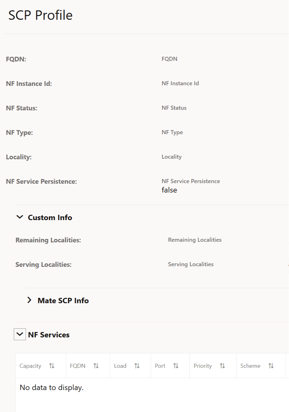
- Click Edit under NF
Services section. The Edit SCP Profile
Screen appears. For more information about configuration parameters, see
Oracle Communications Cloud Native Core, Service Communication Proxy REST
Specification Guide.
Note:
To add a new location to Remaining Localities and Serving Localities, type the new location name, and then click Enter.
Note:
Use Edit or Delete buttons available in the next column to update or delete the NF services.4.2.16 Configuring Service Groups Parameters
- From the left navigation menu, navigate to SCP and then select SCP
Groups.
Figure 4-49 Service Groups

- Click Edit from
Actions to modify the service groups. The Edit Service Groups
Screen appears.
Note:
You can enter Primary and Secondary Region Localities in the respective field. - Click Save to save the Service Groups.
- Click Refresh to view the updated values on the screen.
4.2.17 Configuring Topology Source Info
- From the left navigation menu,
navigate to SCP and then select Topology Source
Info.
Figure 4-50 Topology Source Info
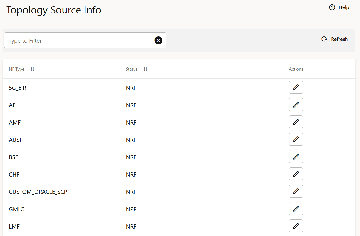
- Click Edit from the Actions column for the required service that must be modified. The Edit Topology Source Info Screen appears.
- Update the Status of the
specific NF Type in the Edit Topology Source Info as per your
requirement.
Figure 4-51 Edit Topology Source Info
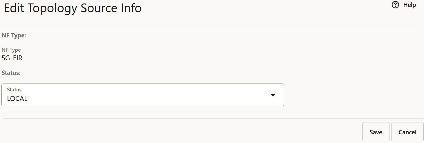
- Click Save to save the Topology Source Info.
- Click Refresh to view the updated values on the screen.
4.2.18 Fetching Routing Rules
- From the left navigation menu, navigate to SCP and then select Reports.
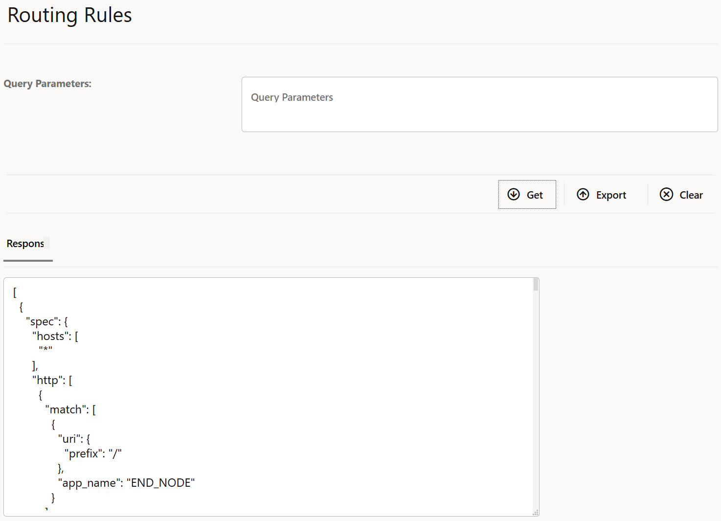
- Select Routing Rules. The Routing Rules screen is
displayed as follows:
Figure 4-52 Routing Rules

- Enter the Query Parameters in the field.
- Click Get to fetch the response data. The data is displayed
in the Response pane.
Figure 4-53 Response data
Note:
In case the response data is above the configured display limit, a message is displayed stating "Response data has crossed the configured display limit (5 MB), please click on Export to download it as a file.". Currently, the display limit cannot be modified, it is set to 5 MB. - Click Export to download of the response data file.
- Click Clear to clear the response data.
4.2.19 Configuring Ingress Rate Limiting
- From the left navigation menu, navigate to SCP and then select Rate Limiting.
- Select Ingress Rate Limiting. The screen is displayed.
Figure 4-54 Ingress Rate Limiting

- Enter the Query Parameters in the field.
- Click Get to fetch the response data. The data is displayed
in the Response pane.
Note:
In case the response data is above the configured display limit, a message is displayed stating "Response data has crossed the configured display limit (5 MB), please click on Export to download it as a file.". Currently, the display limit cannot be modified, it is set to 5 MB. - Click Add to add the ingress rate limiting configuration using the Request Body.
- Click Edit to edit the Request Body of the ingress rate limiting configuration.
- Click Delete to delete the ingress rate limiting configuration based on the query parameters.
4.2.20 Configuring Egress Rate Limiting
- From the left navigation menu, navigate to SCP and then select Rate Limiting.
- Select Egress Rate Limiting. The screen is displayed.
Figure 4-55 Egress Rate Limiting

- Enter the Query Parameters in the field.
- Click Get to fetch the response data. The data is displayed
in the Response pane.
Note:
In case the response data is above the configured display limit, a message is displayed stating "Response data has crossed the configured display limit (5 MB), please click on Export to download it as a file.". Currently, the display limit cannot be modified, it is set to 5 MB. - Click Add to add the egress rate limiting configuration using the Request Body.
- Click Edit to edit the Request Body of the egress rate limiting configuration.
- Click Delete to delete the egress rate limiting configuration based on the query parameters.
4.2.21 Configuring Server Header
4.2.22 Configuring Pod Overload Control Policies
For more information about pod overload policies, see Oracle Communications Cloud Native Core, Service Communication Proxy REST Specification Guide.
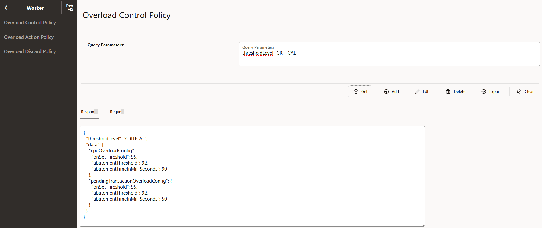
- From the left navigation pane, navigate to SCP and click Pod Overload Control, and then click Worker.
- To configure Pod Overload Control Policy, in the left navigation pane, click
the Overload Control Policy tab.
- To configure Pod Overload Action Policy, in the left navigation pane, click the
Overload Action Policy tab.
- To configure Pod Overload Discard Policy, in the left navigation pane, click
the Overload Discard Policy tab.
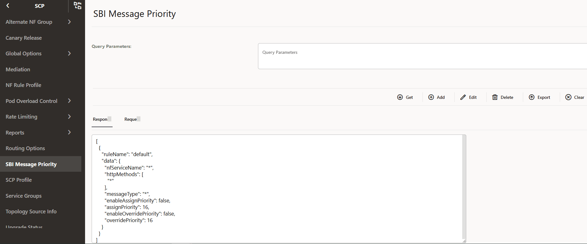
4.2.23 Configuring SBI Message Priority
For more information about SBI Message Priority parameters, see Oracle Communications Cloud Native Core, Service Communication Proxy REST Specification Guide.
4.2.24 Configuring DNS SRV based Alternate Routing
You must log in to the CNC Console while performing the procedures described in the subsequent subsections. Using these procedures, you can perform the followings tasks:
- Set the routing mode.
- Configure the default Time To Live (TTL) value.
- Refresh the DNS SRV records in DB.
- Add and fetch DNS SRV records from DB.
4.2.24.1 Configuring Routing Modes
4.2.24.2 Configuring the Default TTL Value
4.2.25 Configuring SBI Message Priority and Error Profiles
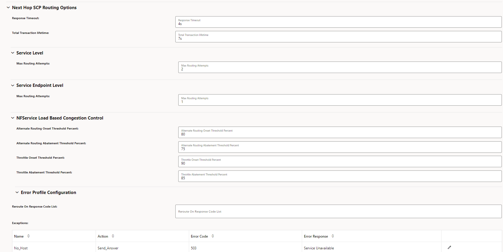
4.2.26 Configuring the nextHopSCP Routing Option
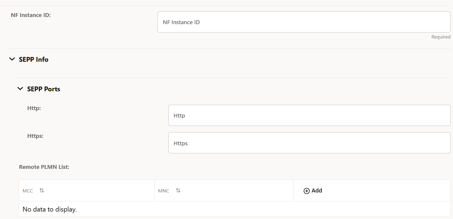
4.2.27 Configuring SEPP Inter PLMN Routing
4.2.28 Configuring Route Groups
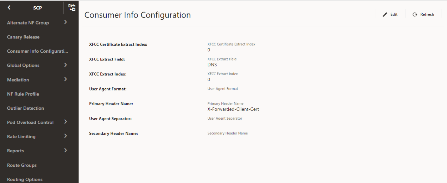
4.2.29 Configuring Ingress Rate Limiter Consumer Info
Perform the following procedure to configure consumer information for ingress rate limiting.
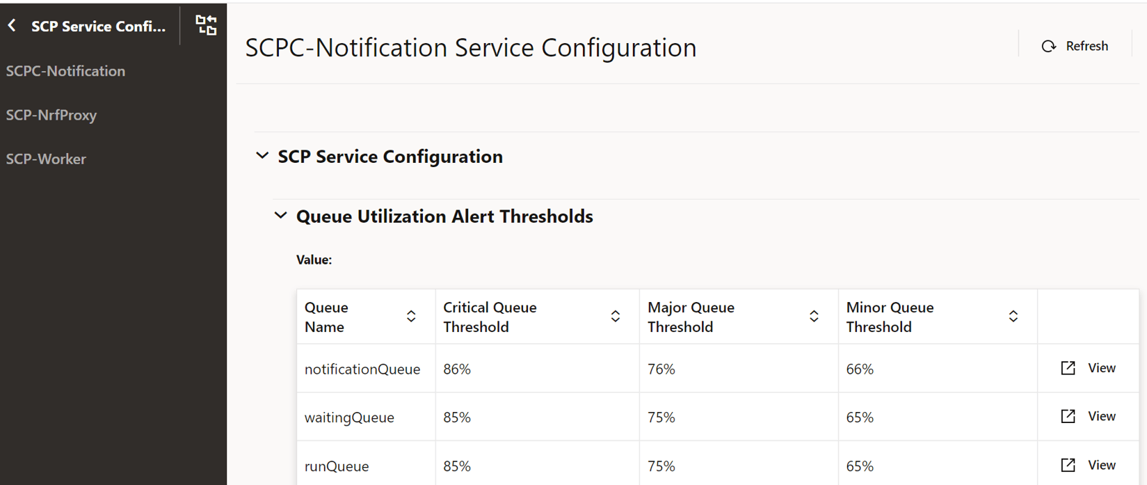
4.2.30 Configuring SCP Services
- From the left navigation pane, click the SCP tab, and then click the SCP Service Configuration tab.
- In the left navigation pane, click the SCPC-AlternateResolution tab and do the following:
- In the SCPC-AlternateResolution Service Configuration section, expand the SCP Service Configuration option.
- To view the Thread Watchdog configuration values, expand the Thread Watchdog Configuration option.
- To view the Connectivity Watchdog configuration values, expand the Connectivity Watchdog Configuration option.
- In the left navigation pane, click the SCPC-Audit tab and do the following:
- In the SCPC-Audit Service Configuration section, expand the SCP Service Configuration option.
- To view the Thread Watchdog configuration values, expand the Thread Watchdog Configuration option.
- To view the Connectivity Watchdog configuration values, expand the Connectivity Watchdog Configuration option.
- In the left navigation pane, click the SCPC-Configuration tab and do the following:
- In the SCPC-Configuration Service Configuration section, expand the SCP Service Configuration option.
- To view the Thread Watchdog configuration values, expand the Thread Watchdog Configuration option.
- To view the Connectivity Watchdog configuration values, expand the Connectivity Watchdog Configuration option.
- In the left navigation pane, click the SCPC-Notification tab and do the following:
- In the left navigation pane, click the SCPC-Subscription tab and do the following:
- In the SCPC-Subscription Service Configuration section, expand the SCP Service Configuration option.
- To view the Thread Watchdog configuration values, expand the Thread Watchdog Configuration option.
- To view the Connectivity Watchdog configuration values, expand the Connectivity Watchdog Configuration option.
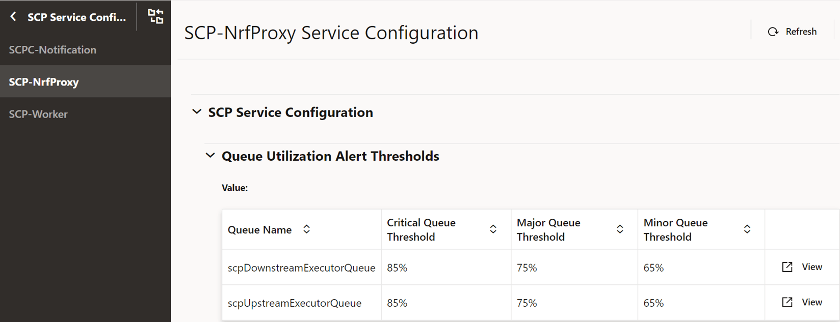
- In the left navigation pane, click the SCP-NrfProxy tab and do the following:
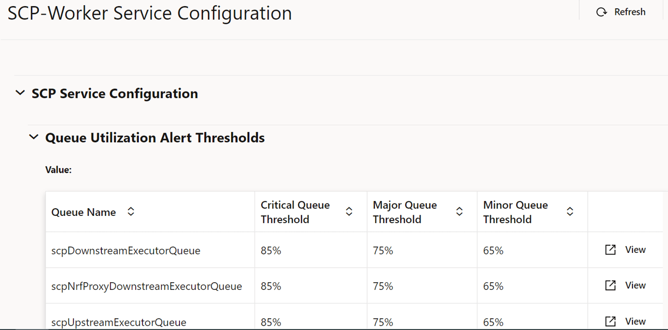
- In the left navigation pane, click the SCP-Worker tab and do the following:
4.2.31 Configuring Outlier Detection
4.2.32 Configuring Traffic Feed
- From the left navigation pane, click the SCP tab, and then click the Traffic Feed tab.
- To configure OCNADD fields, in the left navigation pane, click the Data Director tab.
- In the Traffic Feed Data Director Configuration section, click Edit and configure the fields as described in the "Configuring Traffic Feed Data Director" section of the Oracle Communications Cloud Native Core, Service Communication Proxy REST Specification Guide.
- To configure Trigger Points, in the left navigation pane, click the Trigger Points tab.
- In the Trigger Points section, click Add and configure the fields as described in the "Configuring Traffic Feed Trigger Point Config" section of the Oracle Communications Cloud Native Core, Service Communication Proxy REST Specification Guide.
- Click Save.
4.2.33 Congestion Control Configurations
- From the left navigation menu, navigate to SCP and then select Congestion Control.
- Click Edit icon from the
Actions column for the required service that must be modified.
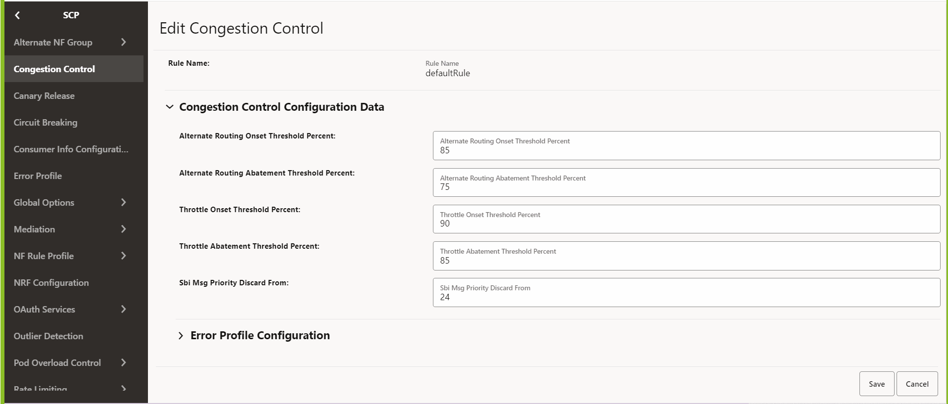
The Edit Congestion Control screen appears.
Note:
The default rule name cannot be deleted. The new rule name can be added, modified, or deleted.Figure 4-72 Congestion Control
- Make the required modifications for the following parameters:
- Alternate Routing Onset Threshold Percent: Set the threshold percentage for onset alternate routing.
- Alternate Routing Abatement Threshold Percent: Set the threshold percentage for alternate routing abatement.
- Throttle Onset Threshold Percent: Set the threshold percentage for onset throttling.
- Throttle Abatement Threshold Percent: Set the threshold percentage for throttle abatement.
- SBI Msg Priority Discard From: Set the priority
for message, after which the messages can be discarded. For example,
if the value is 30, then messages with priority 0-29 are high
priority, and other low-priority messages will be throttled.
Note:
All the parameters are mandatory.
- Click Save.
- Click Cancel to reset all the fields.
- Click Delete from the Actions column to delete the record.
4.2.34 Routing Options Configurations
- From the left navigation menu, navigate to SCP, and then click the Routing Options Configuration tab.
- In the Routing Options Configuration section, click
Edit from the Actions column for the required service that must be
modified.
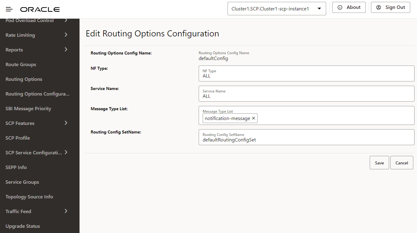
The Edit Routing Options Configuration screen appears.
Figure 4-73 Routing Options Configuration
- In the Routing Options Config
Name, configure the following:
- NF Type: Set the NF type for which routing options are to be configured.
- Service Name: Set the NF service name for the routing options to be configured.
- Message Type List: Set the routing options for notification or SBI messages.
- Routing Options Config SetName: Enter the name of the routing configuration used to retrieve routing options.
- Enter or modify the required values as described in "Routing Options Configuration"and "Routing Config Set" in Oracle Communications Cloud Native Core, Service Communication Proxy REST Specification Guide.
- Click Save.
4.2.35 Routing Config Set
- From the left navigation menu, navigate to SCP, and then click the Routing Config Set tab.
- In the Routing Config Set section, click
Edit from the Actions column for the required service that must be
modified.
The Edit Routing Config Set screen appears.
Figure 4-74 Edit Routing Config Set
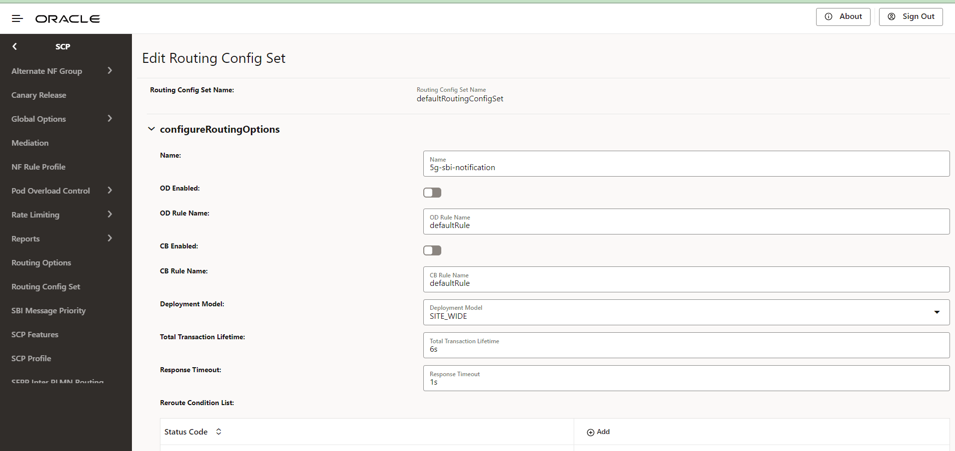
- Enter or modify the required values as described in "Routing Config Set" and "Routing Options Configuration" in Oracle Communications Cloud Native Core, Service Communication Proxy REST Specification Guide.
- In the Reroute Condition
List, configure the list of error codes for rerouting:
- Click Add to add new status code.
- Click Edit or Delete icon to edit or remove any existing error code from the reroute condition list.
- Click Save.
- Click Cancel to reset all the fields.
4.2.36 Circuit Breaking Configurations
- From the left navigation menu, navigate to SCP, and then click the Circuit Breaking tab.
- In the Circuit Breaking section, click Edit
icon from the Actions column for the
required service that must be modified.
The Edit Circuit Breaking screen appears.
Figure 4-75 Edit Circuit Breaking
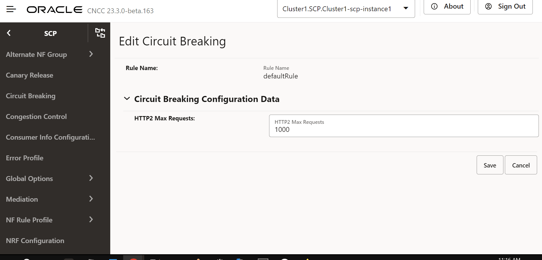
- In the HTTP2 Max Requests field, set the maximum number of requests SCP routes to a NF service instance, waiting for a response before stopping further routing requests to it. The maximum allowed value is 1000.
- Enter or modify the required values as described in "Circuit Breaking Configurations" in Oracle Communications Cloud Native Core, Service Communication Proxy REST Specification Guide.
- Click Save.
- Click Cancel to reset the field.
4.2.37 Viewing SCP Feature Status
Perform the following procedure to fetch the runtime status of NRF migration task.
- From the left navigation pane, click the SCP tab, and then click the SCP Feature Status tab.
- On the SCP Feature Status page, the following
columns display the SCP feature status.
Table 4-43 SCP Feature Status
Column Name Description Feature Name Displays the names of the features, such as nrf_bootstrap_info. Admin State Displays the admin state of the feature. Possible statuses are mentioned below: - ENABLED: This indicates that the user has enabled the feature.
- DISABLED: This indicates that the user has disabled the feature.
Runtime Status Displays the current runtime status of the feature. Possible statuses are mentioned below: - DISABLED: This indicates that the feature is
disabled.
For example, in the nrf_bootstrap_info feature, this state means SCP is running with a statically configured NRF. If the user has changed the 'Admin State' from ENABLED to DISABLED, this state means the feature is successfully disabled.
- IN_PROGRESS: This indicates the enabling or disabling of
the feature is currently is in progress when the 'Admin
State' is set to ENABLED or DISABLED.
For example, in the nrf_bootstrap_info feature, when the 'Admin State' is ENABLED, the migration from static to DNS SRV based NRF topology is in progress. In the nrf_bootstrap_info feature, when the 'Admin State' is DISABLED, the migration from a DNS SRV based NRF topology to static NRF topology is in progress.
- FAILED_RETRY: This indicates that the process of
enabling or disabling the feature (as indicated by the
'Admin State') has encountered failure and is undergoing
retries.
For example, in the nrf_bootstrap_info feature, this state means either of the migration tasks has failed and going through retries.
- ENABLED: This indicates the feature is successfully
enabled.
For example, in the nrf_bootstrap_info feature, this state means the migration from static to a DNS SRV based NRF topology is successful.
Creation Timestamp Displays the time of creation of the event, for example, creationTimestamp": "2021-05-26T01:17:15.000+00:00 Update Timestamp Displays the time of updation of the event, for example, creationTimestamp": "2021-05-26T06:24:15.000+00:00
