4 Configuring Network Exposure Function using the CNC Console
This chapter provides information about how to configure and modify different services in Network Exposure Function (NEF) using the Oracle Communications Cloud Native Configuration Console (CNC Console).
The REST API configurations can also be performed using the CNC Console.
Note:
While installing CNC Console, configure helm config section as the following:- instances field to be configured with NEF and CAPIF type.
- fqdn field to be configured with fivegc-ingress-gateway for NEF and network-ingressgateway for CAPIF.
- port field to be configured with corresponding http1.0 port info
- owner field of other configs to be configured with id
4.1 Support for Multicluster Deployment
The CNC Console supports both single and multiple cluster deployments.
In a single cluster deployment, the CNC Console can manage NFs and Oracle Communications Cloud Native Environment (OCCNE) common services deployed in the local Kubernetes clusters.
In a multicluster deployment, the CNC Console manages NFs and OCCNE common services deployed in the remote Kubernetes clusters. For more information about single and multiple cluster deployments, see Oracle Communications Cloud Native Configuration Console Installation, Upgrade, and Fault Recovery Guide.
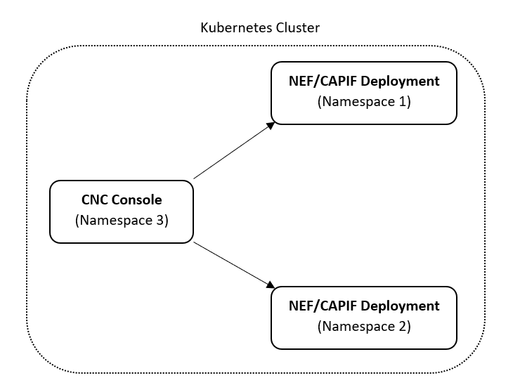
With multicluster deployment, a single instance of the CNC Console can configure two or multiple instances of NEF deployments if both CNC Console and NEF/CAPIF instances are deployed in the same Kubernetes cluster with different namespaces.
The following image represents a Kubernetes cluster with one instance of CNC Console and two instances of NEF/CAPIF. The single instance of the CNC Console is configuring two instances of NEF/CAPIF with different namespaces.
Figure 4-1 Support for Multicluster Deployment
4.2 CNC Console Interface
This section provides an overview of the CNC Console to configure NEF and CAPIF features.
C:\Windows\System32\drivers\etc location.
- In the Windows system, open the hosts file
in the notepad as an Administrator and append the following set of lines at
the end:
<CNCC Node IP> cncc-iam-ingress-gateway.cncc.svc.cluster.local <CNCC Node IP> cncc-core-ingress-gateway.cncc.svc.cluster.localExample:10.75.212.88 cncc-iam-ingress-gateway.cncc.svc.cluster.local 10.75.212.88 cncc-core-ingress-gateway.cncc.svc.cluster.localNote:
The IP Address in the above lines may change when deployment cluster changes. - Save and close the hosts file.
Before logging in to the CNC Console, create a CNC user and password. Log in to the CNC Console using the same credentials. For information about creating a CNC Console user and password, see Oracle Communications Cloud Native Configuration Console Installation, Upgrade, and Fault Recovery Guide.
Logging in to the CNC Console and Selecting an NEF Instance
Perform the following procedure to log in to the CNC Console and select the required NEF instance to configure NEF features.
- Open any web browser.
- Enter the URL:
http://<host name>:<port number>.Where,
<host name>is cncc-iam-ingress-ip and<port number>is cncc-iam-ingressport. - Enter the login credentials.
- Click Log
in.
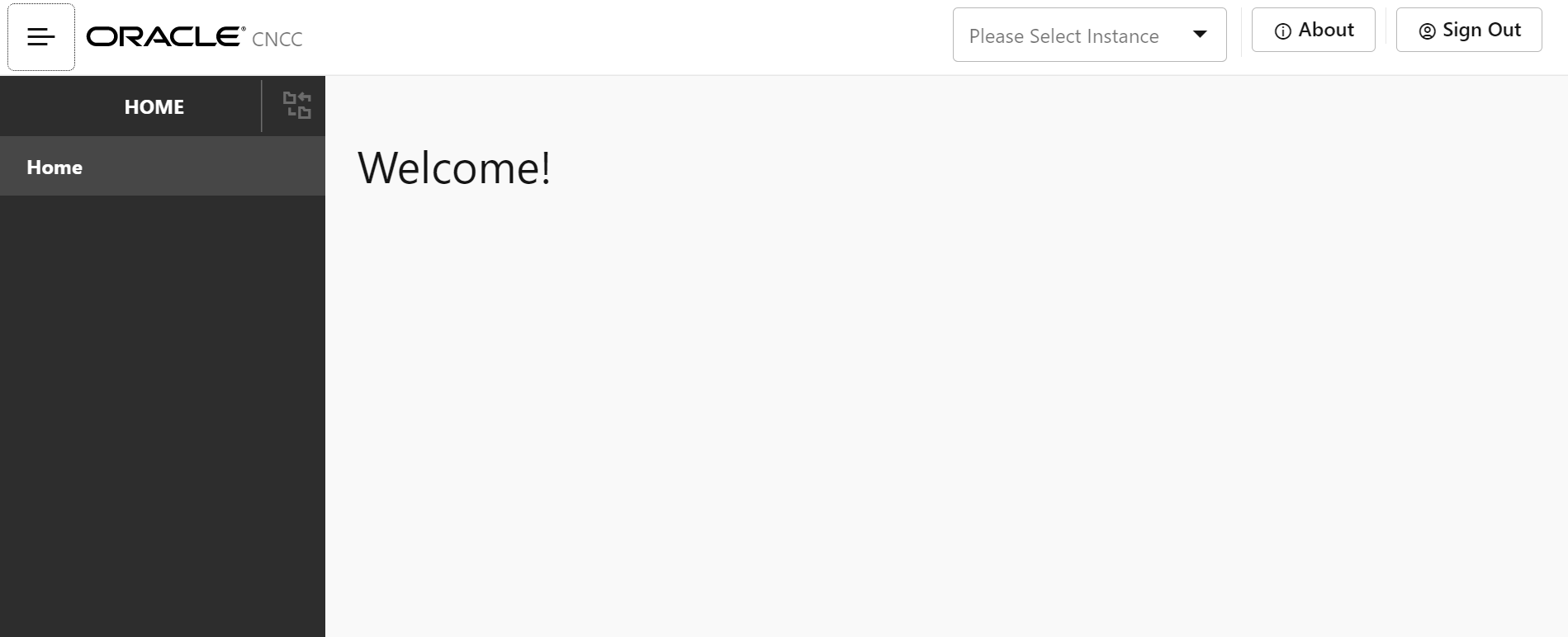
The CNC Console Home page appears.
Figure 4-2 CNC Console Welcome Screen
- In the upper pane, from the Please Select
Instance drop-down list, select the required NEF instance.
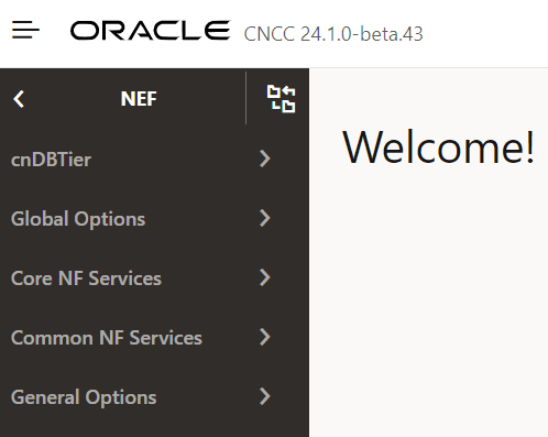
The NEF tab appears in the left navigation pane.
Figure 4-3 Select NF Instance

Figure 4-4 NF Instance for NEF
 The Please Select Instance drop-down list provides NF instances to configure corresponding NF features. You must select an appropriate NEF instance to configure NEF features. Alternatively, you can click one of the following interface elements on the Welcome screen:
- About: This element provides the CNC Console product name and version.
- Sign Out: This element exits the CNC Console.
Figure 4-5 NF Instances
4.2.1 Configuring NEF Features
Note:
You must log in to the CNC Console while performing the procedures described in the subsequent subsections.- Configuring log level for various services
- Configuring AF Service ID mapping
- Configuring QoS Reference Profile
- Configuring AF ID mapping
- Configuring GMLC options
- Configuring QoS options
- Configuring Short or Long Code for MSISDNless MO SMS
- Configuring SCS Short Messaging Entity
- Configuring PLMN Id mapping
- Configuring TAI mapping
- Configuring ECGI mapping
- Configuring NCGI mapping
- Configuring GNB ID mapping
- Configuring Global RAN Node ID mapping
- Configuring Geo Zone Id To Spatial Validity mapping
4.2.1.1 Configuring Log Level for Services
Perform the following procedure to update log level for various services.
- On the left navigation pane, click the NEF tab,
then General Options, and then Logging Level
Options tab.
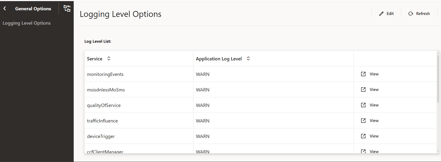
The current list of services in NEF deployment and the corresponding log levels appears.
Figure 4-6 Logging Level Options
- Click Edit to change log level of a specific service
type.
The Edit Logging Level Options page appears.
Figure 4-7 Edit Logging Level Options
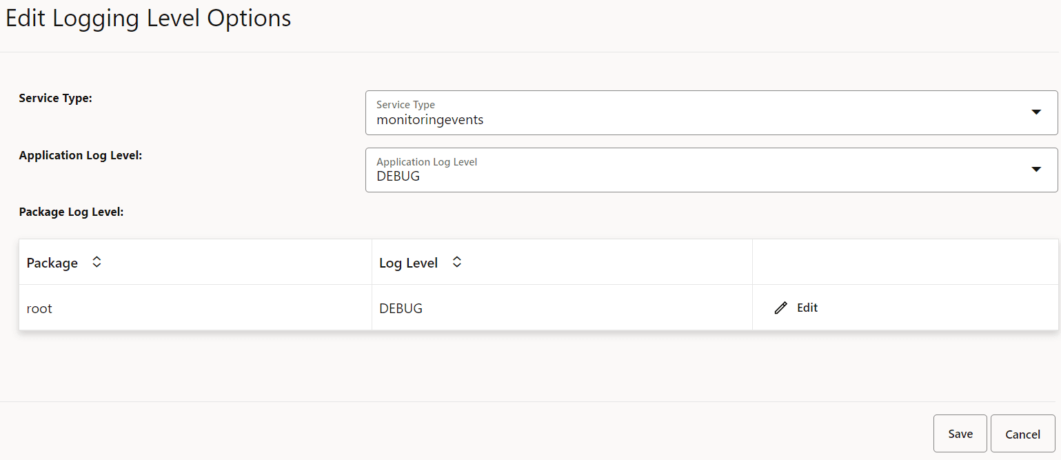
- Select the required Service Type and the corresponding Application Log Level.
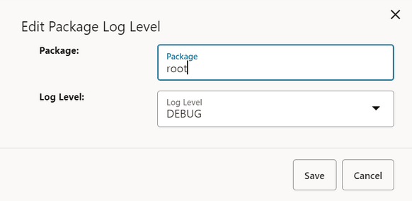
- Click Edit to change the Package and
Log Level of the corresponding Service Type.
Figure 4-8 Edit Package Log Level
- Click Save.
4.2.1.2 Configuring AF Service ID Mapping
Perform the following procedure to add AF service Id configuration applicable for Traffic Influence feature.
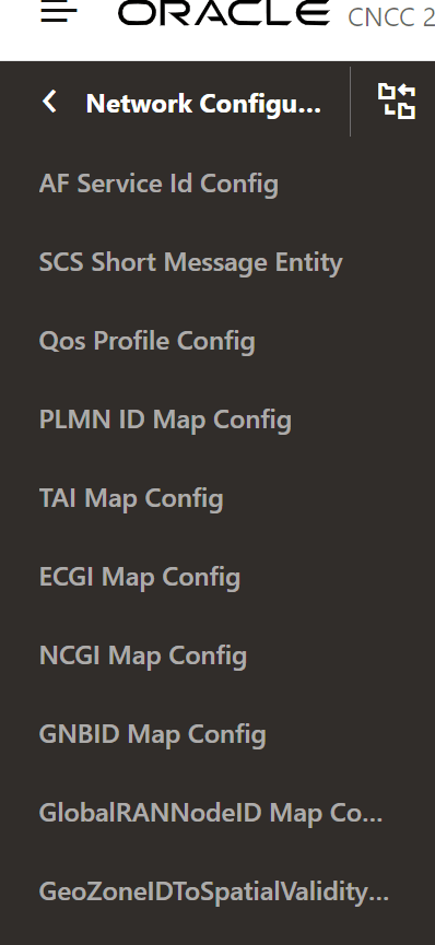
- On the left navigation pane, click the NEF tab,
then Global Options, and then Network
Configuration tab.
Figure 4-9 Network Configuration
- Click AF Service Id Config.
- Click Add to create new config entry for a AF Service ID.
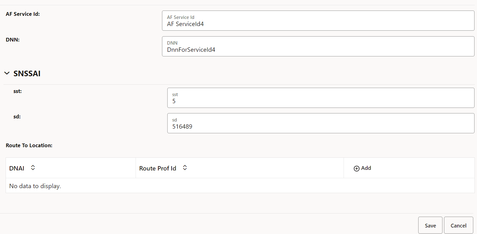
- Update AF Service Id along with the corresponding DNN and Single Network
Slice Selection Assistance Information (S-NSSAI) field values appropriately.
Figure 4-10 AF Service Id Edit Page
- Click Save, then select Add Route To Location.
- In Add Route To Location page, add or update Route To
Location for DNAI, Route Profile Id along with Route Information.
Figure 4-11 Add Route To Location
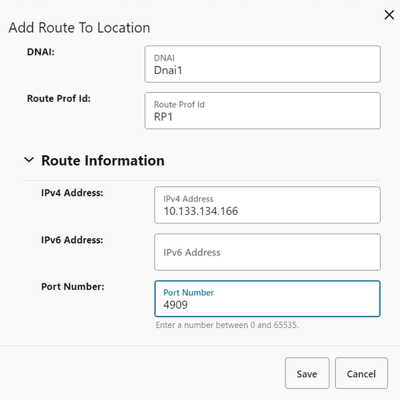
Figure 4-12 AF Service Id Configuration
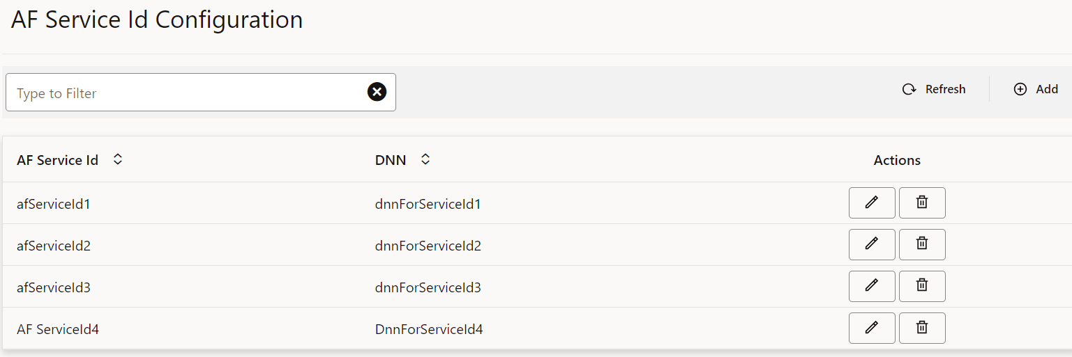
- Click Save.
4.2.1.3 Configuring QoS Reference Profile
Perform the following procedure to add AF service Id configuration applicable for AF Session with Qos feature.
- On the left navigation pane, click the NEF tab,
then Global Options, and then Network
Configuration tab.
Figure 4-13 Network Configuration
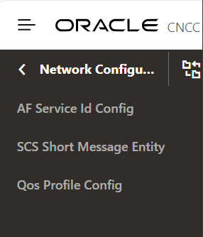
- Click QoS Profile Config to view QoS Profile
Configuration.
Figure 4-14 QoS Profile Configuration

4.2.1.4 Configuring AF ID Mapping
Perform the following procedure to add, update, and delete AF Id mapping configuration.
- On the left navigation pane, click the NEF tab,
then Global Options.
Figure 4-15 Global Options
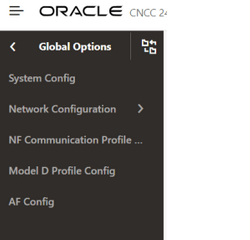
- Click AF Config to add AF Id based DNN, SNSSAI
config.
Figure 4-16 AF Config Page

Figure 4-17 AF Identifier Page
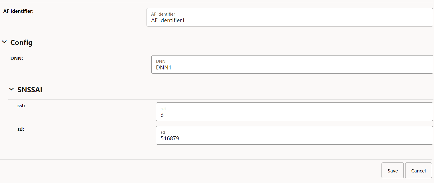
- Click Save.
Figure 4-18 AF Config Id Added

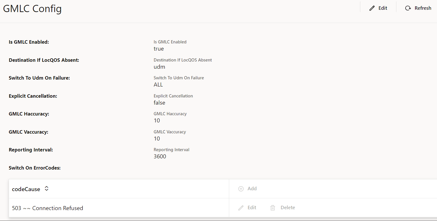
4.2.1.5 Configuring GMLC Options
Perform the following procedure to add/update/delete GMLC configuration for Monitoring Events feature.
- On the left navigation pane, click the NEF tab,
and then Core NF Services.
Figure 4-19 Core NF Services
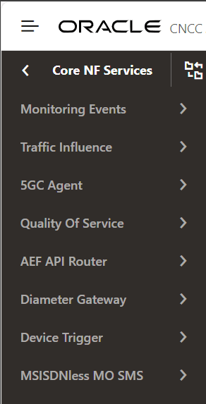
- Click Monitoring Events and then GMLC
options for ME Service.
Figure 4-20 GMLC Config

Note:
Edit GMLC operation is only valid when GMLC is enabled.Incase if GMLC is enabled during installation, then further GMLC config is enabled.
Figure 4-21 GMLC Enabled
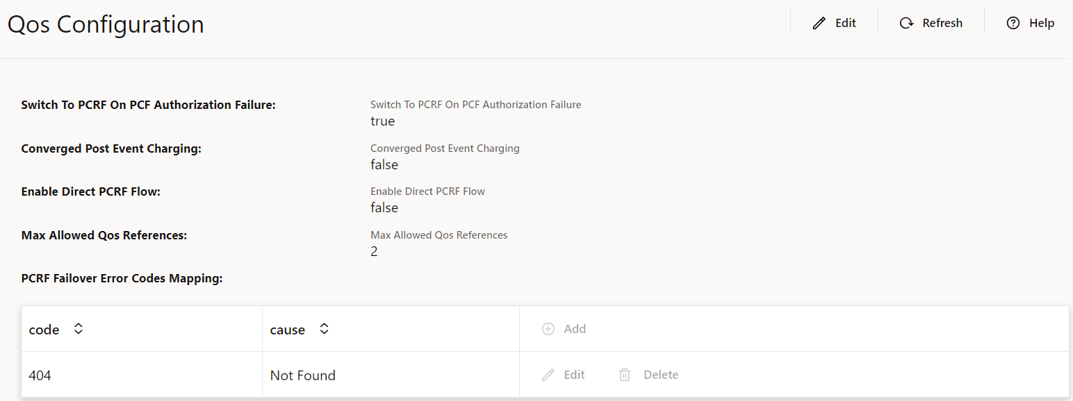
4.2.1.6 Configuring QoS Options
Following configurations are readonly and shall be updated only through Helm installation.
- Switch to PCRF on PCF Authorization Failure
- Enable Direct PCRF Flow
Perform the following procedure to configure QoS Options.
- On the left navigation pane, click the NEF tab,
then Core NF Services, and then Quality of
Service tab.
Figure 4-22 Core NF Services

- Incase if Switch To PCRF on PCF Authorization
Failure is enabled, then PCRF Failover Error Code Mapping is
configured further.
Figure 4-23 QoS Configuration
4.2.1.7 Configuring Short or Long Code for MSISDNless MO SMS
Perform the following configuration for enabling short code mapping for MSISDNless MO SMS feature.
- On the left navigation pane, click the NEF tab,
then Core NF Services, and then MSISDNless MO
SMS tab.
Figure 4-24 Core NF Services

Figure 4-25 Shortcode Notification

- Click Shortcode Configuration.
Figure 4-26 Shortcode Configuration

4.2.1.8 Configuring SCS Short Messaging Entity
Perform the following procedure to add AF service Id configuration applicable for Traffic Influence feature.
Figure 4-27 Network Configuration

Figure 4-28 SCS Short Message Entity Configuration

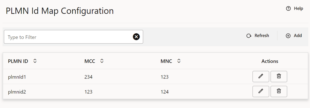
4.2.1.9 Configuring PLMN ID Mapping
Perform the following procedure to configure PLMN ID mapping.
Figure 4-29 PLMN ID Map Configuration
Note:
You can modify or delete an existing configuration by using the respective actions.Adding PLMN ID Mapping
- Click Add.
- In Create PLMN Id Map Configuration window, enter PLMN ID, MCC, and MNC configuration.
- Click Save.
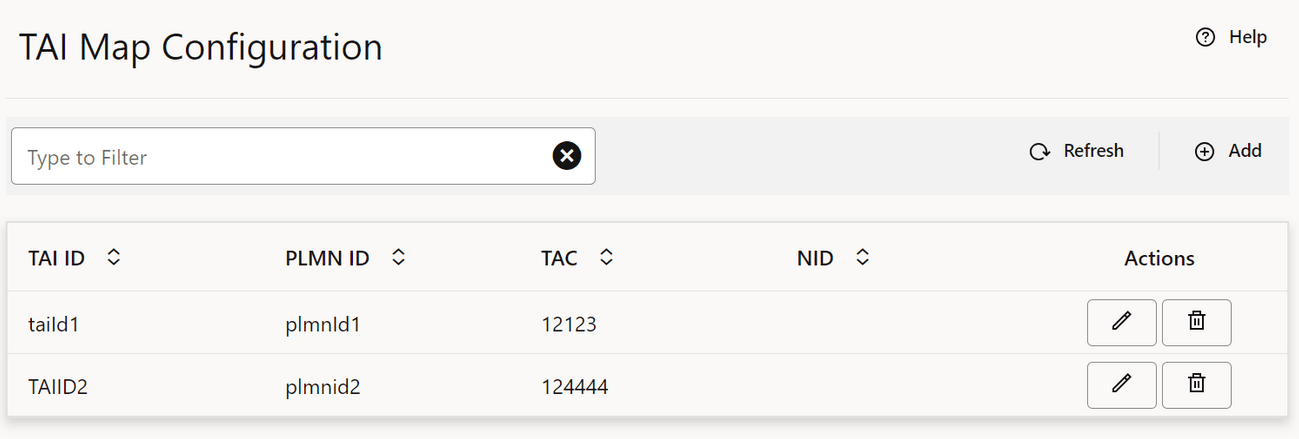
4.2.1.10 Configuring TAI Mapping
Perform the following procedure to configure TAI mapping.
Figure 4-30 TAI Map Configuration
Note:
You can modify or delete an existing configuration by using the respective actions.Adding TAI Mapping
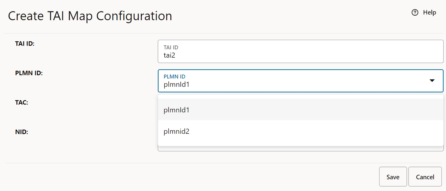
- TAI Map should be associated with the configured PLMN ID Map. All the configured PLMN ID Map are available in the drop-down, PLMN ID. Refer to Configuring PLMN ID Mapping for configuring PLMN ID map.
- Click Add.
- In Create TAI Map Configuration window, enter
TAI ID, PLMN ID, TAC, and NID configuration.
Note:
PLMN ID is a dynamic drop-down option based on the configuration in PLMN ID map.Figure 4-31 Create TAI Map Configuration
- Click Save.
4.2.1.11 Configuring ECGI Mapping
Perform the following procedure to configure ECGI mapping.
Figure 4-32 ECGI Map Config

Note:
You can modify or delete an existing config by using the respective actions.Adding ECGI Mapping
- PLMN ID map should be configured with appropriate values that need to be linked to ECGI MAP (dropdown option). Refer to Configuring PLMN ID Mapping for configuring PLMN ID map.
- Click Add
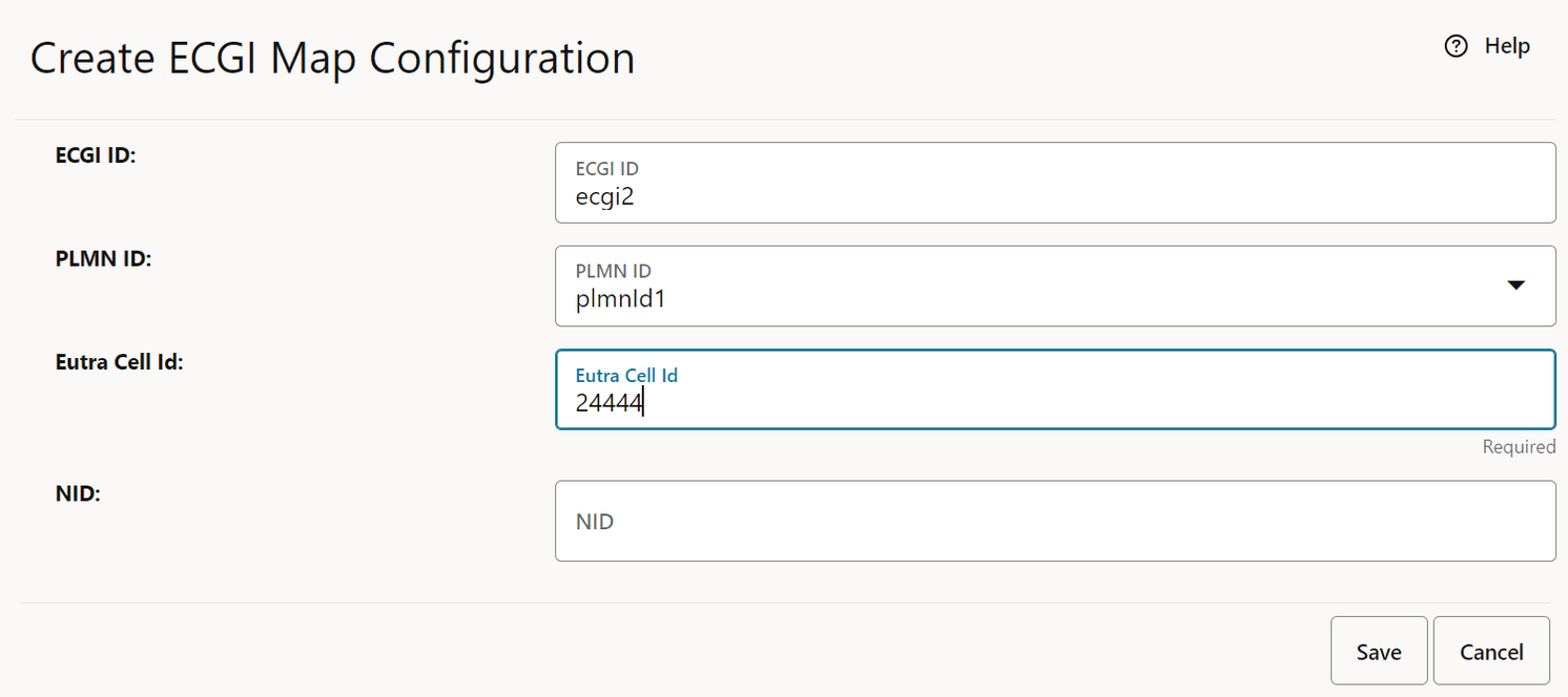
- In Create ECGI Map Configuration window,
enter ECGI ID, PLMN ID, Eutra Cell Id and NID configuration.
Note:
PLMN ID is a dynamic dropdown option based on the configuration in PLMN ID map.Figure 4-33 Create ECGI Map Configuration
- Click Save
4.2.1.12 Configuring NCGI Mapping
Perform the following procedure to configure NCGI mapping.
Figure 4-34 NCGI Map Config

Note:
You can modify or delete an existing config by using the respective actions.Adding NCGI Mapping
- PLMN ID map should be configured with appropriate values that need to be linked to NCGI MAP (dropdown option). Refer to Configuring PLMN ID Mapping for configuring PLMN ID map.
- Click Add
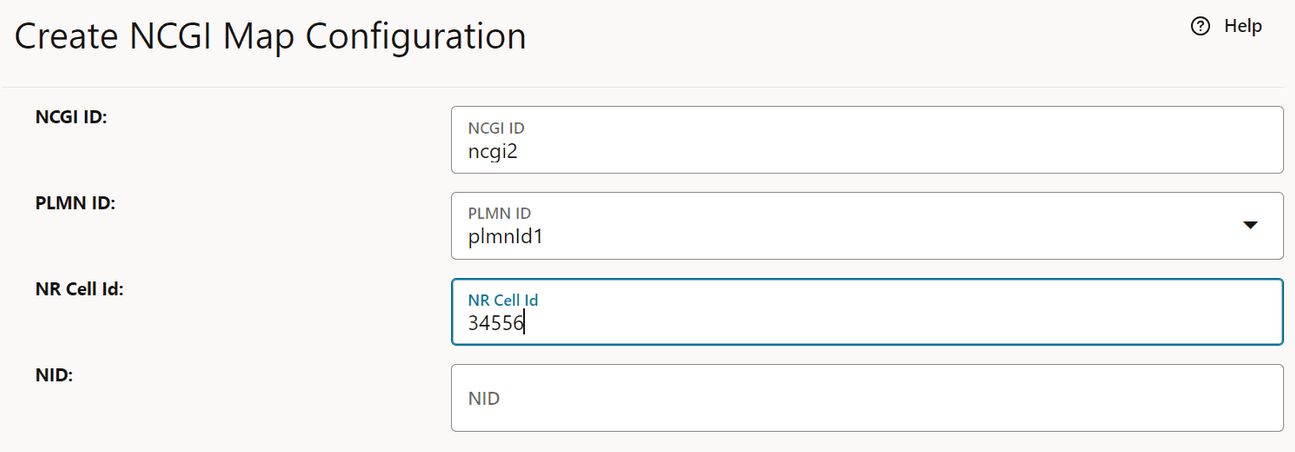
- In Create NCGI Map Configuration window,
enter NCGI ID, PLMN ID, NR Cell Id and NID configuration.
Note:
PLMN ID is a dynamic dropdown option based on the configuration in PLMN ID map.Figure 4-35 Create NCGI Map Configuration
- Click Save
4.2.1.13 Configuring GNBID Mapping
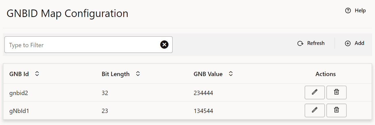
Perform the following procedure to configure GNBID mapping.
Figure 4-36 GNBID Map Config
Note:
You can modify or delete an existing config by using the respective actions.Adding GNBID Mapping
- Click Add
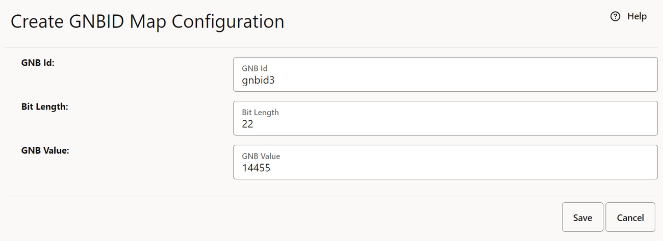
- In Create GNBID Map Configuration window,
enter GNBID, Bit Length and GNB value.
Figure 4-37 Create GNBID Map Configuration
- Click Save
4.2.1.14 Configuring GlobalRANNodeID Mapping
Perform the following procedure to configure GlobalRANNodeID mapping.
Figure 4-38 GlobalRANNodeID Map Config

Note:
You can modify or delete an existing config by using the respective actions.Adding GlobalRANNodeID Mapping
- PLMN ID map and GNBID map should be configured with appropriate values that need to be linked to GlobalRANNodeID MAP (dropdown option). Refer to Configuring PLMN ID Mapping for configuring PLMN ID map and Configuring GNBID Mapping for configuring GNBID map.
- Click Add
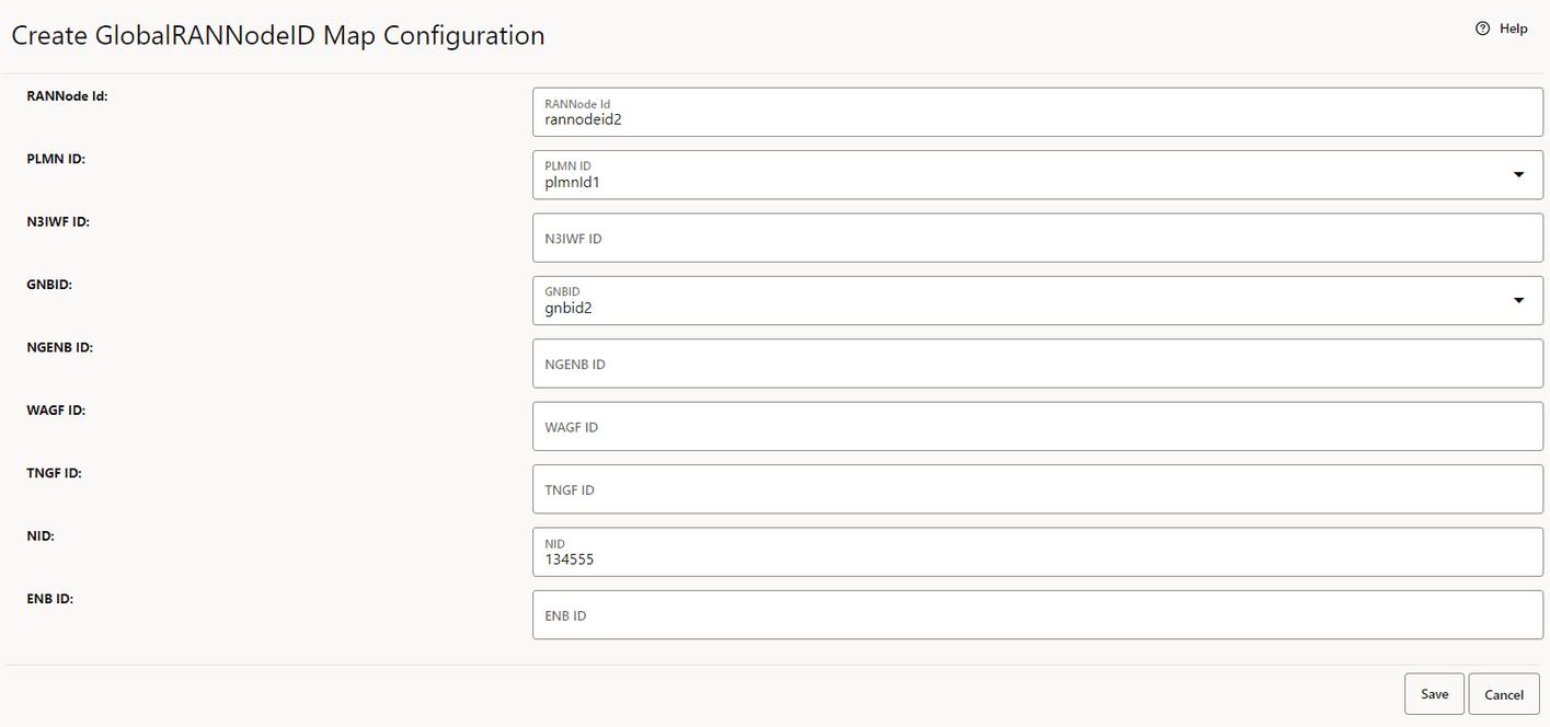
- In Create GlobalRANNodeID Map Configuration
window, enter RANNode Id, PLMN ID, N3IWF ID, GNBID ,NGENB ID, WAGF ID, TNGF ID ,
ENB ID and NID configuration.
Note:
PLMN ID and GNBID is a dynamic dropdown option based on the configuration.Figure 4-39 Create GlobalRANNodeID Map Configuration
- Click Save
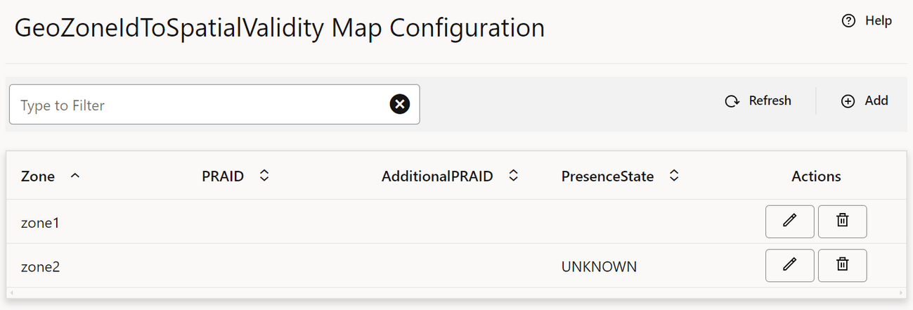
4.2.1.15 Configuring GeoZoneIdToSpatialValidity Mapping
Perform the following procedure to configure GeoZoneIdToSpatialValidity mapping applicable for Traffic Influence feature.
Figure 4-40 GeoZoneIdToSpatialValidity Map Config
Note:
You can modify or delete an existing config by using the respective actions.Adding GeoZoneIdToSpatialValidity Mapping
- TAI map, ECGI map, NCGI map and GlobalRANNodeID map should be
configured with appropriate values that need to be linked to
GeoZoneIdToSpatialValidity MAP (dropdown option) attributes which are
TrackingArea List, ECGI List, NCGI List, GlobalRANNodeID List, globaleNBID List
respectively. Refer to:
- Configuring TAI Mapping for configuring TAI map
- Configuring ECGI Mapping for configuring ECGI map
- Configuring NCGI Mapping for configuring NCGI map
- Configuring GlobalRANNodeID Mapping for configuring GlobalRANNodeID map
- Click Add
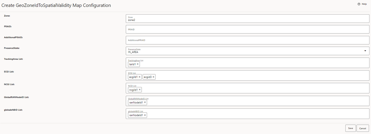
- In Create GeoZoneIdToSpatialValidity Map
Configuration window, enter appropriate values for Zone, PRAID,
AdditionalPRAID, PresenceState, TrackingArea List, ECGI List, NCGI List ,
GlobalRANNodeID List and globaleNBID List.
Note:
TrackingArea List, ECGI List, NCGI List, GlobalRANNodeID List, and globaleNBID List are dynamic dropdown multi-select option based on the configuration.Figure 4-41 Create GeoZoneIdToSpatialValidity Map Configuration

Figure 4-42 Create GeoZoneIdToSpatialValidity Map Configuration
- Click Save
4.2.1.16 Viewing Global System Config
Perform the following procedure to view Global System Config.
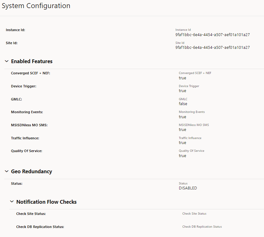
On the left navigation pane, click the NEF tab, then Global Options, and then System Config.
- Current Site details and peer site configurations are displayed, in case if Geo Redundancy is enabled.
- List of features that are enabled or disabled in the current deployment are shown.
- If GR is enabled, notification flow handling is shown.
Figure 4-43 System Configuration
4.2.1.17 Configuring Gateway
4.2.1.17.1 Configuring Routes
Perform the following configurations for enabling SBI routing.
Peer Configuration
- On the left navigation pane, click the NEF tab, then Common NF Services, and then 5gc Core Egress Gateway.
- Select Peer Configuration and click Add to create a new entry for Peer Configuration.
- Click Save to complete the
configuration.
Figure 4-44 Peer Configuration

Figure 4-45 Peer Configuration - Edit

Peer Set Configuration
- On the left navigation pane, click the NEF tab, then Common NF Services, and then 5gc Core Egress Gateway.
- Select Peer Set Configuration and click
Add to create a new entry for Peer Set Configuration.
Refer to the Peer ID configured in previous step.
Figure 4-46 Create Peer Set Configuration
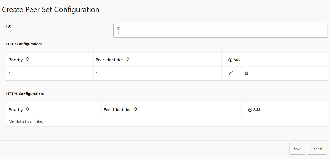
- Click Save to complete the configuration.
Route Configuration
- On the left navigation pane, click the NEF tab, then Common NF Services, and then 5gc Core Egress Gateway.
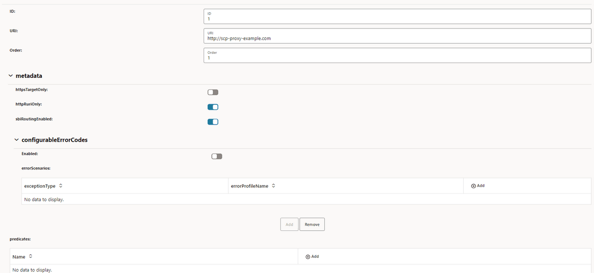
- Select Routes Configuration and click
Add to add a new Route configuration.
Figure 4-47 Route Configuration
SBI Error Action Sets
- On the left navigation pane, click the NEF tab, then Common NF Services, and then 5gc Core Egress Gateway.
- Select SBI Error Action Sets.
Figure 4-48 SBI Error Action Sets

SBI Error Criteria Sets
- On the left navigation pane, click the NEF tab, then Common NF Services, and then 5gc Core Egress Gateway.
- Select SBI Error Criteria Sets.
Figure 4-49 SBI Error Criteria Sets

4.2.1.18 Viewing cnDBTier APIs in CNC Console
Perform the following procedure to view cnDBTier APIs in CNC Console.
Backup List
On the left navigation pane, click the NEF tab, then cnDBTier, and then BackupList.Figure 4-50 Backup List

cnDBTier Version
On the left navigation pane, click the NEF tab, then, cnDBTier, and then cnDBTier Version.Figure 4-51 cnDBTier Version

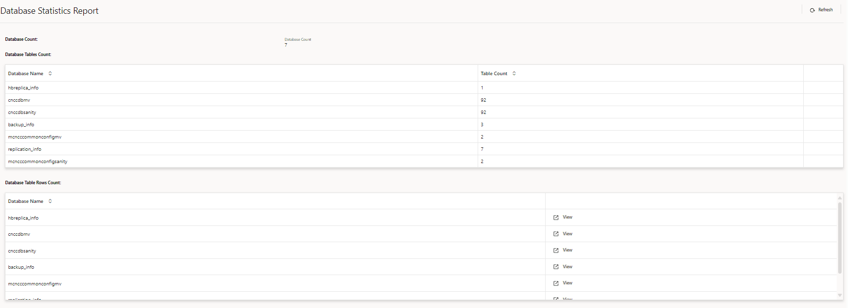
Database Stats
On the left navigation pane, click the NEF tab, then, cnDBTier, and then Database Statistics Reports.Figure 4-52 Database Statistics Reports
GeoReplication Status
On the left navigation pane, click the NEF tab, then, cnDBTier, and then GeoReplication Status.Figure 4-53 GeoReplication Status

HeartBeat Status
On the left navigation pane, click the NEF tab, then, cnDBTier, and then HeartBeat Status.Figure 4-54 HeartBeat Status

Local Cluster Status
On the left navigation pane, click the NEF tab, then, cnDBTier, and then Local Cluster Status.Figure 4-55 Local Cluster Status

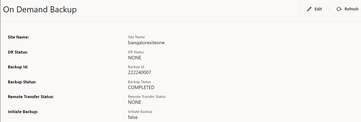
On Demand Backup
On the left navigation pane, click the NEF tab, then, cnDBTier, and then On Demand Backup.Figure 4-56 On Demand Backup
Replication Health Status
- On the left navigation pane, click the NEF tab, then, cnDBTier, and then cnDBTier Health.
- Click Replication Health Status.
Figure 4-57 Replication Health Status

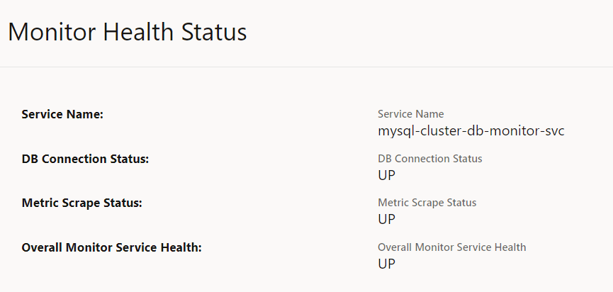
Monitor Health Status
- On the left navigation pane, click the NEF tab, then, cnDBTier, and then cnDBTier Health.
- Click Monitor Health Status.
Figure 4-58 Monitor Health Status
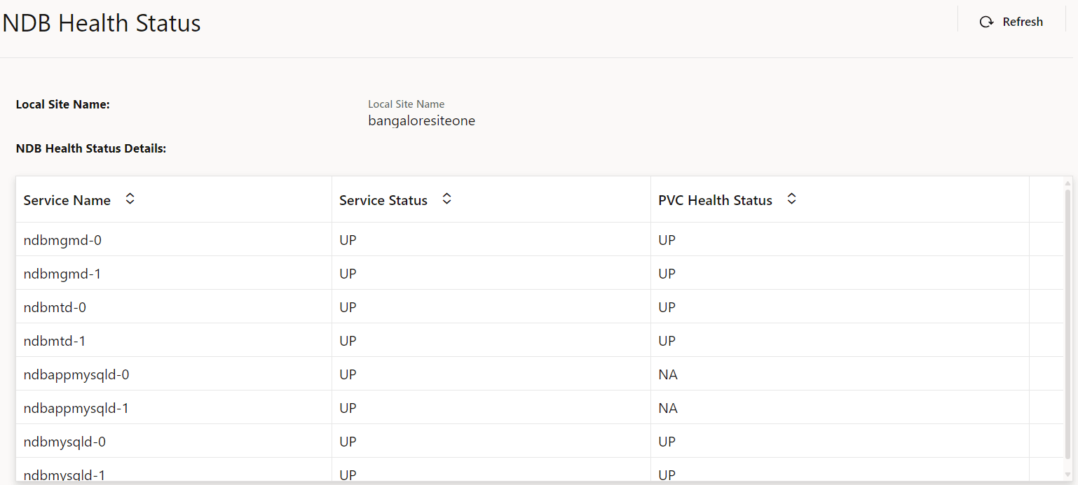
NDB Health Status
- On the left navigation pane, click the NEF tab, then, cnDBTier, and then cnDBTier Health.
- Click NDB Health Status.
Figure 4-59 NDB Health Status
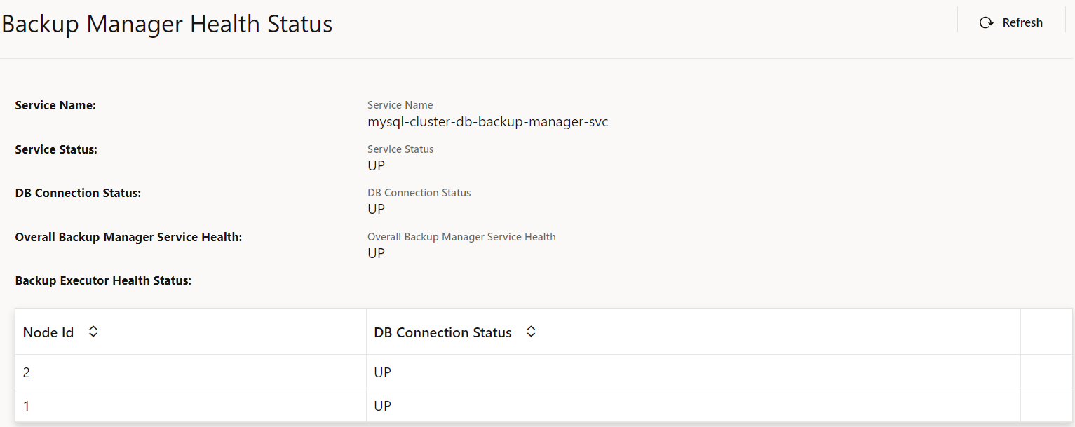
Backup Manager Health Status
- On the left navigation pane, click the NEF tab, then, cnDBTier, and then cnDBTier Health.
- Click Backup Manager Health Status.
Figure 4-60 Backup Manager Health Status
4.2.2 Configuring CAPIF Features
This section provides information about enabling the following features of CAPIF:
Note:
You must log in to the CNC Console while performing the procedures described in the subsequent subsections.- Configuring log level for various services
- Configuring Invoker Access Token
- Configuring discovery group
- Configuring invoker pre-provisioning
4.2.2.1 Configuring Log Level for Services
Perform the following procedure to update log level for various services.
- On the left navigation pane, click the CAPIF
tab, then General Options, and then Logging Level
Options tab.
The current list of services in CAPIF deployment and the corresponding log levels appears.
Figure 4-61 Logging Level Options

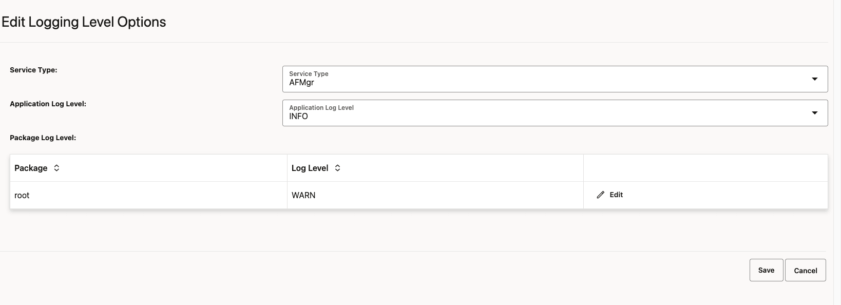
- Click Edit to change log level of a specific
service type.
The Edit Logging Level Options page appears.
- Select the required Service Type and the
corresponding Application Log Level.
Figure 4-62 Edit Logging Level Options
- Click Edit to change the
Package and Log Level of the
corresponding Service Type.
Figure 4-63 Edit Package Log Level
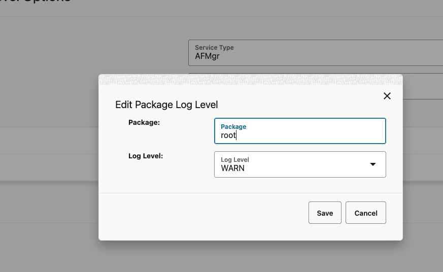
- Click Save.
4.2.2.2 Configuring Invoker Access Token
Perform the following procedure to update the expiry time for Invoker Access Token.
- On the left navigation pane, click the CAPIF tab, then Core Capif Services, and then AF Manager tab.
- On the left navigation pane, click Access Token
Config.
Figure 4-64 Invoker Access Token Configuration

- Click Edit to change the expiryTime value.
The Edit Invoker Access Token Configuration page appears.
Figure 4-65 Edit Invoker Access Token Configuration

- Click Save.
4.2.2.3 Configuring Discovery Group
Note:
You can delete the existing config by using the Delete button on the config.- On the left navigation pane, click the CAPIF tab and then General Option tab.
- To view the Discovery group, on the left navigation pane, click Discovery
Group.
Figure 4-66 Discovery Groups

- Click Add to create new discovery group.
- Provide the Discovery Group ID name and select nef services
from the drop down list.
Figure 4-67 Adding Discovery Group

- Click Save.
Figure 4-68 Discovery Group Added

4.2.2.4 Configuring Invoker Pre-provisioning
Perform the following procedure to add or update or delete Invoker Pre-provisioning.
- On the left navigation pane, click the CAPIF tab and then General Option tab.
- To add or update or delete API Invoker, on the left navigation pane, click
Invoker Pre-Provisioning.
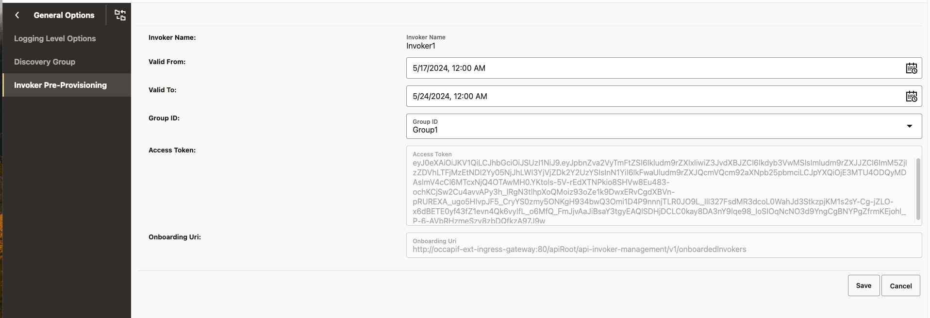
Figure 4-69 Invoker Pre-Provisioning

Figure 4-70 Edit Invoker Pre-Provisioning
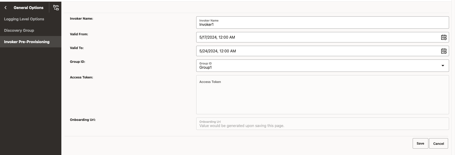
- Click Save.
Figure 4-71 Invoker Pre-Provisioning

- To open the invoker and copy the Access token and Onboarding URI details, click
Edit action icon.
Figure 4-72 Edit Invoker Pre-Provisioning
