6 EAGLE 5 Integrated Monitoring Support Configuration

Chapter 7, EAGLE 5 Integrated Monitoring Support Configuration, describes the Eagle 5 Integrated Monitoring Support feature and the procedures necessary to configure the EAGLE to support this feature.

Introduction

The EAGLE 5 Integrated Monitoring Support feature allows the network traffic on the EAGLE’s signaling links to be monitored by an ESP (extended services platform) or IMF (integrated message feeder) without additional intrusive cabling.

To monitor the network traffic on the EAGLE’s signaling links without this feature requires physical, clamp-on connections to the EAGLE's SS7 signaling links (see Figure 6-1). This monitoring method involves costs for cable installation and maintenance for each SS7 link that is to be monitored.

Figure 6-1 Monitoring via Hardware Connection

img/c_introduction_integrated_mon_suppor_configuration_dbadmin_features-fig1.jpg

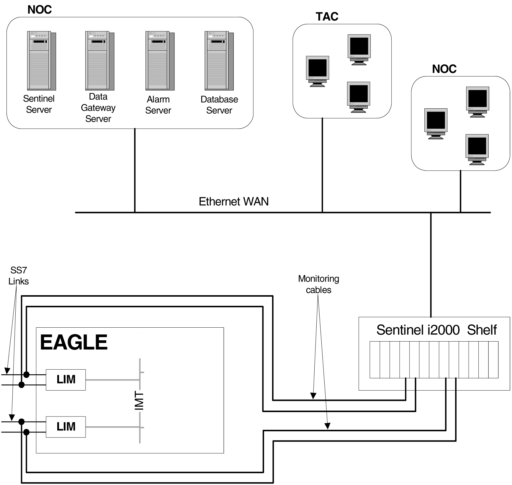
This feature eliminates the need to have intrusive hardware for each link that is to be monitored. The monitoring is performed by an Ethernet connection from an STC (Signaling Transport Card) or an FC-capable card to the ESP/IMF (see Figure 6-2 ). An FC-capable card is a card that is configured to copy traffic directly to an IMF subsystem over its Fast Copy interfaces. Currently, cards running the IPGHC and IPSG GPLs are the only supported FC-capable cards. Message Signaling Units (MSUs), alarms, and events may be copied to the ESP/IMF subsystem over the Ethernet link to provide the network traffic monitoring.

Figure 6-2 EAGLE 5 Integrated Monitoring Support Network Connectivity


img/e5is_network_116458.jpg

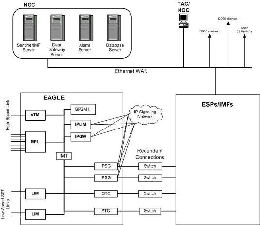
As can be seen in Figure 6-2 , this new method of connectivity removes the cabling and clamps from each monitored SS7 link. By incorporating a TCP/IP stack on each LIM and having the STCs or FC-capable cards serve as IP routers, the ESP/IMF subsystem may communicate directly with the SS7 LIMs. Figure 6-3 shows the logical communications pathway.

Figure 6-3 ESP/IMF/EAGLE Network


img/esp_imf_eagle_network_161235.jpg

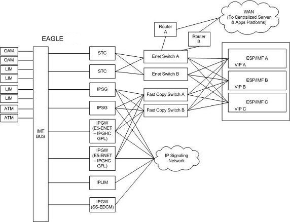
The STC communicates to the LIM by the IMT bus; the IP messages are simply encapsulated in an IMT wrapper between the cards. The STCs are provisioned in an n+1 configuration for redundancy. Each STC Ethernet port has a separate connection path to each Ethernet switch in order to provide an alternate path in the event of an Ethernet link failure. Note that the figure depicts a redundant network; this assures that a single network failure will not halt EAGLE or ESP/IMF operations. As shown in Figure 6-3 , one or more ESP/IMF may be connected to a single Ethernet switch. The number of STCs required corresponds to the number of SS7 links that are to be associated with the EAGLE Integrated Monitoring Support feature, plus an additional STC for redundancy.

The LIMs are assigned private network addresses. The IP message origination address specified is that of the LIM. The IP message destination address is that of the VIP (virtual IP address) contained within the ESP/IMF server. The STC serves as a router from the LIM to the ESP/IMF servers.

TCP/IP Link Provisioning

The IP communications link, used to transmit copied MSUs between the EAGLE and the ESP/IMF subsystem, is dynamically configured by the Sentinel/IMF. This is performed automatically as part of the operations for coming into service. A special function, part of the card's application software, is to establish communications with the ESP/IMF subsystem by sending a service request message (see Figure 6-4, Figure 6-5, and Figure 6-6).

Figure 6-4 Ethernet Link Establishment - EMP Link Data


img/emp_link_data_stc_116458.jpg

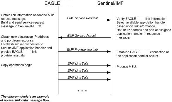
Figure 6-5 Ethernet Link Establishment - EMP Fast Copy Link PDU


img/emp_link_data_fast_copy_116458.jpg

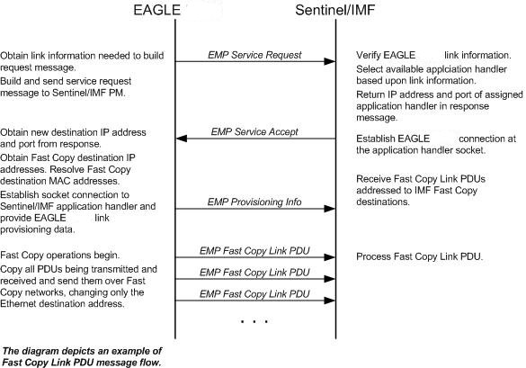
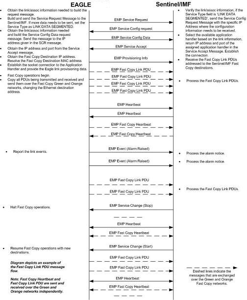
Figure 6-6 Ethernet Link Establishment - EMP Fast Copy Link PDU Modified for the IPGHC GPL


img/fast_copy_link_pdu_scr_161235.jpg

The LIM receiving the service accept response then opens a new socket using the specified IP address and port as the destination using standard TCP/IP socket messaging. The ESP/IMF server configured to service the port responds to the connect request and the socket is now available for normal operations. MSUs are copied from the LIM through the STC or FC-capable cards (if the Fast Copy function is being used) to the ESP/IMF server, then to the Sentinel/IMF.

The IPGHC GPL supports up to 50 associations per E5-ENET card. Each card hosts one SS7 signaling link. Sending information for 50 associations to the IMF requires a large UDP message. Network elements generally restrict broadcasting large UDP data. It is not guaranteed that the large Service Request Message (UDP broadcast) can reach the IMF in all networks. The Service Config Request Message and Service Config Data Message, shown in Figure 6-6, are used to send the large configuration information to the IMF.

The Service Request Message is sent with the “Service Type” field set to “LINK DATA SEGMENTED”. The IMF responds with a Service Config Request Message querying the configuration data by specifying the IP address and UDP port where the large configuration data needs to be sent. The card running the IPGHC GPL sends (UDP unicast) the configuration data to the specific IP address and UDP port included in the Service Config Request Message.

If the LIM is unsuccessful with its initial link service request, it will re-attempt link establishment with the ESP/IMF subsystem after delaying for a short period (that is, approximately 15 seconds). The LIM continuously repeats the link establishment procedure until it is successful. If the LIM ever loses its IP connection to the ESP server, the LIM will automatically begin reestablishment operations.

The STCs use Dynamic Host Configuration Protocol to provision themselves with IP addresses. The ESP/IMF subsystem contains a DHCP server and a DHCP client resides on the STC. The STC receives its IP address from the DHCP server in accordance with the DHCP standard.

The IP addresses of an FC-capable card is automatically assigned to the card as the card is brought into service. Each card is assigned two IP addresses, one for Fast Copy network A and the other for Fast Copy network B. The network portion of the IP addresses is determined from the FCNA and FCNAMASK (for the Fast Copy network A IP addresses) and the FCNB and FCNBMASK (for the Fast Copy network B IP addresses) values shown in the rtrv-netopts command output. The value of the host portion of the IP address for an FC-capable card is the IMT address of the card+1.

A custom routing protocol manages the multiple redundant links and provides a faster network convergence than is possible with standard routing protocols.

Time Stamping

The MSU information will be delivered to the ESP/IMF subsystem with an accurate time stamp (± 5 milliseconds). This allows the Sentinel/IMF to correlate a call's messages for CDR (Call Detail Record) operations.

EAGLE Provisioning

To provision this feature, these items are required:

  • STC cards are installed in the EAGLE
  • If the Fast Copy function is being used to copy traffic from IPSG cards (the FCMODE=FCOPY and FCGPL=IPSG values are shown in the rtrv-eisopts output), cards running the IPSG GPL must be installed in the EAGLE. The state of at least one of the cards running the IPSG GPL must be IS-NR.
  • If the Fast Copy function is being used to copy traffic from cards running the IPGHC GPL (the FCMODE=FCOPY and FCGPL=IPGHC values are shown in the rtrv-eisopts output), cards running the IPGHC GPL must be installed in the EAGLE. The state of at least one of the cards running the IPGHC GPL must be IS-NR.
  • The TSC (Time Slot Counter) Synchronization feature is enabled in the EAGLE 5. TSC synchronization is supplied by the E5-MASP or E5-MCAP cards in card locations 1113 and 1115.

  • A timing source for the low-speed signaling links and for the TSC (Time Slot Counter) synchronization feature

    If the EAGLE does not contain LIMDS0 cards, but contains TDM part numbers 870-0774-15 or later, the clock source for any low-speed links and for the TSC (Time Slot Counter) synchronization feature used by the Sentinel/IMF can be generated from the high-speed source clock source. An external BITS clock is not required.

    If an external BITS clock is connected to an EAGLE without LIMDS0 cards, but with TDM part numbers 870-0774-15 or later, the external BITS clock must be used as the clock source for any low-speed links and for the TSC (Time Slot Counter) synchronization feature.

    If LIMDS0 cards are present in the EAGLE, the external BITS clock is required for timing of the DS0 signaling links and for TSC (Time Slot Counter) synchronization used by the Sentinel/IMF. If the EAGLE also contains TDM part numbers 870-0774-15 or later along with the LIMDS0 cards, this procedure can be used to select the source of the high-speed source clock for the high-speed links using external timing.The high-speed source clock source cannot be used to generate the clock source for any low-speed links and for the TSC (Time Slot Counter) synchronization feature.

  • A Network Time Protocol (NTP) timing source from the ESP/IMF server
  • The EAGLE shelves can contain HIPR2 cards. Shelves containing IPLIMx, IPSG or IPGWx cards that are being monitored must contain HIPR2 cards.

An “n + 1" STC configuration is required to provide redundancy for this feature.

The connection from the EAGLE to the ESP is an Ethernet connection with a minimum bandwidth of 10 Mbps. The dual-slot STC contains two 10 Mbps Ethernet ports. The single-slot STC contains two 100 Mbps Ethernet ports. FC-capable cards require a 100 Mbps/full duplex configuration for copying traffic to the ESP. If the IP port on the FC-Capable card is not able to auto-negotiate to this speed/duplex configuration, then the traffic will not be copied from this port to the ESP.

Refer to Hardware User Reference for more information about the E5-MCAP cards and STCs.

The n+1 STC configuration requires that a minimum of two STCs must be provisioned in the database. If single-slot STCs are being provisioned in the database, a minimum of two single-slot STCs must be provisioned.

Table 6-1 shows the signaling links on these cards can be monitored by this feature.

Table 6-1 Monitored Card Types

Card Application (APPL Value Used by the ent-card Command Card Type (TYPE Value Used by the ent-card Command) Card Name
SS7ANSI LIMDS0 E5-E1T1, E5-E1T1-B card
SS7ANSI, CCS7ITU LIME1 E5-E1T1, E5-E1T1-B card
LIMT1 E5-E1T1, E5-E1T1-B card
ATMANSI LIMATM E5-ATM , E5-ATM-B
ATMITU LIME1ATM E5-ATM, E5-ATM-B
SS7IPGW DCM E5-ENET, E5-ENET-B card
IPGWI DCM E5-ENET, E5-ENET-B card
IPSG ENET E5-ENET, E5-ENET-B card

Notes:

Only signaling links assigned to M2PA associations can be monitored on the cards running the IPLIM and IPLIMI applications. This can be verified by entering the rtrv-assoc:adapter=m2pa command.

Signaling links assigned to M3UA associations can be monitored on the cards running the SS7IPGW and IPGWI applications. This can be verified by entering the rtrv-assoc:adapter=m3ua command. Signaling links assigned to SUA associations can be monitored only on cards that are running the IPGHC GPL in the STC and Fast Copy monitoring modes.

Monitoring can be performed on E5-E1T1 cards, E5-E1T1-B cards, E5-ENET cards, and E5-ENET-B cards using only the IMF.

Monitoring can be performed on channelized E1 signaling links and unchannelized E1 signaling links (assigned to the LIME1 card type). A channelized E1 signaling link is a signaling link that is assigned to a channelized E1 port, shown by the entry CHAN in the LINKCLASS field in the rtrv-e1 output. An unchannelized E1 signaling link is a signaling link that is assigned to an unchannelized E1 port, shown by the entry UNCHAN in the LINKCLASS field in the rtrv-e1 output.

The signaling links assigned to the cards running either the ss7ansi or ccs7itu applications are low-speed signaling links transmitting at either 56 kbps or 64 kbps. Signaling links assigned to the atmansi and atmitu applications are high-speed signaling links transmitting at 1.544 Mbps (atmansi) or 2.048 Mbps (atmitu). Signaling links assigned to the iplim, iplimi, ss7ipgw, ipsg, and ipgwi applications are IP signaling links.

Because the performance of a single-slot STC is higher than a dual-slot STC, a dual-slot STC cannot replace a single-slot STC. If a single-slot STC replaces a dual-slot STC, and it is the only single-slot STC in the EAGLE, another single-slot STC must be added to the EAGLE. To add the additional single-slot STC, go to Adding a Signaling Transport Card (STC).

In order to perform the necessary IP routing within the EAGLE switch, a private virtual network (PVN) is incorporated; the PVN represents the internal IP addressing scheme for every STC within the EAGLE switch. Each card has an auto-assigned, default, Class B private IP address (for example, 172.28.60.16).

Note:

The EAGLE uses a default value of 172.20.48.0 for the PVN address. You may change the default value by specifying a new network portion of an IP address and a network mask; the host portion is auto-configured. The EAGLE requires use of the lower 8 bits of address space for auto-configuration of internal networking schemes. The entered mask value may be up to 255.255.255.0

Network Considerations

There are three networks used to connect the EAGLE to the ESP/IMF subsystem (see Figure 6-3 :

  • The EAGLE containing the STCs and FC-capable cards (if the Fast Copy function is being used).
  • The two Ethernet switches
  • The ESP/IMF servers

The monitored information is sent from the EAGLE to the ESP/IMF servers through the Ethernet switches, then forwarded to the Sentinel/IMF by the isolation routers. Each router will have one Ethernet port designated as the physical demarcation point between the customer network and the ESP/IMF subsystem.

IP Address Provisioning

The ESP/IMF subsystem requires IP addresses for these items:

  • ESP/IMF external network:
    • Three IP addresses on the customer network for the ESP/IMF isolation routers, one IP address for HSRP, one IP address for each router (two total)
    • One netmask
    • One IP address for the default router.
  • ESP/IMF internal network – Contiguous IP block routed within their network (last octet range 1-67 for 17 servers). The Sentinel/IMF considers each ESP/IMF server a separate processing element, therefore each ESP/IMF server needs its own IP address.
  • Routes to their network to route to the VIP network already defined within ESP/IMF subsystem.

    Caution:

    These IP addresses can be changed, as well as the PVNIP address in the EAGLE, contact the Customer Care Center (refer to unresolvable-reference.html#GUID-3FA61F5C-C612-4DBC-B090-8EF65AD958FD for the contact information) before changing these IP addresses.

Route Configuration

No explicit routing tables are provisioned in the ESP/IMF subsystem. Use of the single customer provided default router address is assumed for outgoing traffic. All incoming traffic will use the HSRP address provided by the isolation routers.

Network Limitations

The maximum length of the network cables between the ESP/IMF server frame and the STC cards is limited to 328 feet (100 meters). This limitation is the maximum length that any 10/100BaseT cable can be run.

Enabling the Time Slot Counter Synchronization (TSCSYNC) and EAGLE 5 Integrated Monitoring Support (E5IS) Features

The EAGLE 5 Integrated Monitoring Support feature requires that the Time Slot Counter Synchronization (TSCSYNC) and EAGLE 5 Integrated Monitoring Support (E5IS) features are enabled with the chg-feat command using the tscsync and e5is parameters. This procedure is used to enable these features.

Note:

Once the Time Slot Counter Synchronization and EAGLE 5 Integrated Monitoring Support features are turned on with the chg-feat command, they cannot be turned off.

The Time Slot Counter Synchronization and EAGLE 5 Integrated Monitoring Support features must be purchased before turning on these features. If you are not sure whether you have purchased the Time Slot Counter Synchronization or EAGLE 5 Integrated Monitoring Support features, contact your Oracle Sales Representative or Account Representative.

  1. Verify that the EAGLE 5 Integrated Monitoring Support feature and Time Slot Counter Synchronization features are on, by entering the rtrv-feat command.

    If the EAGLE 5 Integrated Monitoring Support feature is on, the E5IS field should be set to on. If the Time Slot Counter Synchronization feature is on, the TSCSYNC field should be set to on.

    Note:

    The rtrv-feat command output contains other fields that are not used by this procedure. If you wish to see all the fields displayed by the rtrv-feat command, see the rtrv-feat command description in the Commands User's Guide.

    If the Time Slot Counter Synchronization and the EAGLE 5 Integrated Monitoring Support features are not turned on, or just the Time Slot Counter Synchronization feature is turned on, continue the procedure with 2.

    If both the EAGLE 5 Integrated Monitoring Support feature and Time Slot Counter Synchronization features are on, then no further action is necessary. If you wish to change the EISCOPY and FCMODE values in the rtrv-eisopts output, the PVN, PVNMASK, FCNA, and FCNB values in the rtrv-netopts output, or add STC cards, perform the following procedures.
  2. Turn the Time Slot Counter Synchronization and EAGLE 5 Integrated Monitoring Support features on by entering one of these commands, depending on whether or not the rtrv-feat output in 1 shows that the Time Slot Counter Synchronization feature is on.

    If the Time Slot Counter Synchronization feature is not on, enter this command.

    chg-feat:tscsync=on:e5is=on

    If the Time Slot Counter Synchronization feature is on, enter this command.

    chg-feat:e5is=on

    Note:

    Once the Time Slot Counter Synchronization and EAGLE 5 Integrated Monitoring Support features are turned on with the chg-feat command, they cannot be turned off.

    The Time Slot Counter Synchronization and EAGLE 5 Integrated Monitoring Support features must be purchased before turning on these features. If you are not sure whether you have purchased the Time Slot Counter Synchronization or EAGLE 5 Integrated Monitoring Support features, contact your Oracle Sales Representative or Account Representative.

    When the chg-feat has successfully completed, this message should appear.

    
    rlghncxa03w 06-10-20 21:18:37 GMT EAGLE5 36.0.0
    CHG-FEAT: MASP A - COMPLTD
    
  3. Verify the changes by entering the rtrv-feat command.

    If the EAGLE 5 Integrated Monitoring Support feature is on, the E5IS field should be set to on. If the Time Slot Counter Synchronization feature is on, the TSCSYNC field should be set to on.

  4. Back up the new changes using the chg-db:action=backup:dest=fixed command.
    These messages should appear, the active Maintenance and Administration Subsystem Processor (MASP) appears first.
    
    BACKUP (FIXED) : MASP A - Backup starts on active MASP.
    BACKUP (FIXED) : MASP A - Backup on active MASP to fixed disk complete.
    BACKUP (FIXED) : MASP A - Backup starts on standby MASP.
    BACKUP (FIXED) : MASP A - Backup on standby MASP to fixed disk complete.
    
  5. When the EAGLE 5 Integrated Monitoring Support feature is turned on, the values for the EISCOPY and FCMODE values in the rtrv-eisopts output, and the PVN, PVNMASK, FCNA, and FCNB values in the rtrv-netopts output are set to their default values. If you wish to change any of these values or add STC cards, perform the following procedures.

Figure 6-7 Enabling the Time Slot Counter Synchronization (TSCSYNC) and EAGLE 5 Integrated Monitoring Support (E5IS) Features


Configuring the EISCOPY Option for the EAGLE 5 Integrated Monitoring Support Feature

This procedure is used to configure the EISCOPY option for the EAGLE 5 Integrated Monitoring Support feature using the chg-eisopts command with the eiscopy parameter.

The chg-eisopts command can also be used to configure the FCMODE option. Perform Configuring the FCMODE Option for the EAGLE 5 Integrated Monitoring Support Feature to configure the FCMODE option.

The eiscopy parameter contains two values, on and off. The eiscopy=on parameter enables the EISCOPY function for the EAGLE 5 Integrated Monitoring Support feature. The eiscopy=off parameter turns off the EISCOPY function for the EAGLE 5 Integrated Monitoring Support feature. The EISCOPY function allows the EAGLE to copy MSUs to the ESP/IMF subsystem. The default value for the eiscopy parameter is off.

To change the EISCOPY option, the EAGLE 5 Integrated Monitoring Support feature (E5IS) must be turned on.

  1. Verify that the EAGLE 5 Integrated Monitoring Support feature is on, by entering the rtrv-feat command.

    If the EAGLE 5 Integrated Monitoring Support feature is on, the E5IS field should be set to on.

    Note:

    The rtrv-feat command output contains other fields that are not used by this procedure. If you wish to see all the fields displayed by the rtrv-feat command, see the rtrv-feat command description in Commands User's Guide.

    If the EAGLE 5 Integrated Monitoring Support feature is not on, perform Enabling the Time Slot Counter Synchronization (TSCSYNC) and EAGLE 5 Integrated Monitoring Support (E5IS) Features to turn on the EAGLE 5 Integrated Monitoring Support feature. After the EAGLE 5 Integrated Monitoring Support feature is turned on, the EISCOPY and FCMODE values, shown in the rtrv-eisopts output, are off. After the EAGLE 5 Integrated Monitoring Support feature is turned on, continue the procedure with 3.

    If the EAGLE 5 Integrated Monitoring Support feature is on, continue the procedure with 2.

  2. Display the EISCOPY option by entering the rtrv-eisopts command.

    This is an example of the possible output.

    
    rlghncxa03w 10-07-07 11:43:04 GMT EAGLE5 42.0.0
    EIS OPTIONS
    ------------------
    EISCOPY = OFF
    
    FAST COPY OPTIONS
    --------------------------------
    FCGPL = IPSG      FCMODE = OFF
    FCGPL = IPGHC     FCMODE = OFF
    --------------------------------
    

    If the EISCOPY value is OFF, continue the procedure with 3.

    If the EISCOPY value is ON, continue the procedure with 9.

  3. Display the STC cards in the database using the rept-stat-mon command.

    This is an example of the possible output.

    
    rlghncxa03w 10-07-01 09:12:36 GMT  EAGLE5 42.0.0
    
    CARD   VERSION      PST           SST        AST       TVG   CPU
                                                           USAGE USAGE
    ------------------------------------------------------------------
    1105   126-002-000  IS-NR         Active     -----      35%    52%
    1205   126-002-000  IS-NR         Active     -----      35%    52%
    1211   126-002-000  IS-NR         Active     -----      35%    52%
    1303   126-002-000  IS-NR         Active     -----      35%    52%
    1311   126-002-000  IS-NR         Active     -----      35%    52%
    1313   126-002-000  IS-NR         Active     -----      35%    52%
    2211   126-002-000  IS-NR         Active     -----      35%    52%
    2213   126-002-000  IS-NR         Active     -----      35%    52%
    ------------------------------------------------------------------
    

    Note:

    The rept-stat-mon command output contains other fields that are not used by this procedure. If you wish to see all the fields displayed by the rept-stat-mon command, see the rept-stat-mon command description in Commands User's Guide.

    At least two STCs must be shown in the rept-stat-mon output. The primary state (PST value) of at least two STCs must be IS-NR. If two or more STCs are shown in the rept-stat-mon output and the primary state of at least two of these STCs is IS-NR, continue the procedure with 5 .

    If there are less than two STCs shown in the rept-stat-mon output, add the necessary STCs by performing Adding a Signaling Transport Card (STC). After the STCs have been added, continue the procedure with 5 .

    If two or more STCs are shown in the rept-stat-mon output and the primary state of only one STC is IS-NR, or primary state of all of the STCs is not IS-NR, continue the procedure with 4.

  4. Enter the rst-card command as necessary so that the primary state of at least two of the STCs shown in 3 is IS-NR. Specify the card location of the STC that is not IS-NR, shown in 3, with the rst-card command.

    For this example, enter these commands.

    rst-card:loc=1205

    rst-card:loc=1211

    When this command has successfully completed, this message should appear.

    
    rlghncxa03w 09-02-28 09:12:36 GMT EAGLE5 40.1.0
    Card has been allowed.
    
  5. Display the IP addresses and the PVN subnet mask by entering the rtrv-netopts command.

    This is an example of the possible output.

    
    rlghncxa03w 10-07-28 09:12:36 GMT EAGLE5 42.0.0
    NETWORK OPTIONS
    -----------------
    PVN      = 172.20.48.0
    PVNMASK  = 255.255.252.0
    FCNA     = 172.21.48.0
    FCNAMASK = 255.255.254.0
    FCNB     = 172.22.48.0
    FCNBMASK = 255.255.254.0
    
  6. Display the current link parameters associated with the IP card in the database by entering the rtrv-ip-lnk command.

    The following is an example of the possible output.

    
    rlghncxa03w 10-07-28 21:14:37 GMT EAGLE5 42.0.0
    LOC   PORT IPADDR          SUBMASK         DUPLEX  SPEED MACTYPE AUTO MCAST
    1201  A    192.1.1.1       255.255.255.128 HALF    10    802.3   NO   NO
    1203  A    192.1.1.12      255.255.255.0   ----    ---   DIX     YES  NO
    1205  A    192.1.1.14      255.255.255.0   FULL    100   DIX     NO   NO
    
  7. Display the IP routes in the database with the rtrv-ip-rte command.

    This is an example of the possible output.

    
    rlghncxa03w 10-07-28 09:12:36 GMT EAGLE5 45.0.0
    LOC   DEST             SUBMASK          GTWY
    1301  128.252.10.5     255.255.255.255  140.188.13.33
    1301  128.252.0.0      255.255.0.0      140.188.13.34
    1301  150.10.1.1       255.255.255.255  140.190.15.3
    1303  192.168.10.1     255.255.255.255  150.190.15.23
    1303  192.168.0.0      255.255.255.0    150.190.15.24
    
    IP Route table is  (5 of 2048) 0.24% full
    
  8. The EISCOPY option cannot be turned on if any of these conditions are present.

    The subnet address that results from the PVN and PVNMASK, FCNA and FCNAMASK, or FCNB and FCNBMASK values in the rtrv-netopts output are the same as the subnet address resulting from the IPADDR and SUBMASK values in the rtrv-ip-lnk command, or the DEST and SUBMASK values of the rtrv-ip-rte command.

    The subnet address that results from the PVN and PVNMASK values in the rtrv-netopts output cannot be the same as the subnet addresses that result from the FCNA and FCNAMASK, or FCNB and FCNBMASK values in the rtrv-netopts output.

    The host portion of the subnet address that results from the PVN and PVNMASK value in the rtrv-netopts output is not 0 (zero).

    The PVNMASK value in the rtrv-netopts outputs not one of these values.

    If any of these conditions are present, perform the Configuring the IP Addresses for the EAGLE 5 Integrated Monitoring Support Feature procedure to change the required IP addresses before proceeding to 9.

  9. Change the EISCOPY option by performing one of these substeps.
    1. To turn the EISCOPY option on, enter this command.

      chg-eisopts:eiscopy=on

      If you wish to change the FCMODE values, perform the Configuring the FCMODE Option for the EAGLE 5 Integrated Monitoring Support Feature. This procedure is finished.

    2. To turn the EISCOPY option off and the FCMODE values of all the GPLS shown in the rtrv-eisopts output in 2 is OFF, enter this command.

      chg-eisopts:eiscopy=off

      Caution:

      The EAGLE 5 Integrated Monitoring Support feature will be disabled if the EISCOPY option is turned off.
    3. To turn the EISCOPY option off and the FCMODE values of any of the GPLS shown in the rtrv-eisopts output in 2 is either STC or FCOPY, enter this command.

      chg-eisopts:eiscopy=of:fcgpl=all:fcmode=off

      Caution:

      The EAGLE 5 Integrated Monitoring Support feature will be disabled if the EISCOPY option is turned off.

    When the chg-eisopts has successfully completed, this message should appear.

    
    rlghncxa03w 09-02-20 21:18:37 GMT EAGLE5 40.1.0
    CHG-EISOPTS: MASP A - COMPLTD
    
  10. Verify the changes to the EISCOPY option by entering the rtrv-eisopts command.

    This is an example of the possible output.

    
    rlghncxa03w 10-07-07 11:43:04 GMT EAGLE5 42.0.0
    EIS OPTIONS
    ------------------
    EISCOPY = ON
    
    FAST COPY OPTIONS
    --------------------------------
    FCGPL = IPSG      FCMODE = OFF
    FCGPL = IPGHC     FCMODE = OFF
    --------------------------------
    
  11. Back up the new changes using the chg-db:action=backup:dest=fixed command.

    These messages should appear, the active Maintenance and Administration Subsystem Processor (MASP) appears first.

    
    BACKUP (FIXED) : MASP A - Backup starts on active MASP.
    BACKUP (FIXED) : MASP A - Backup on active MASP to fixed disk complete.
    BACKUP (FIXED) : MASP A - Backup starts on standby MASP.
    BACKUP (FIXED) : MASP A - Backup on standby MASP to fixed disk complete.
    

Figure 6-8 Configuring the EISCOPY Option for the EAGLE 5 Integrated Monitoring Support Feature


Sheet 1 of 2


Sheet 2 of 2

Configuring the FCMODE Option for the EAGLE 5 Integrated Monitoring Support Feature

This procedure is used to configure the FCMODE option for the EAGLE 5 Integrated Monitoring Support feature with the chg-eisopts command and these parameters.

The fcmode parameter specifies a system-wide control to enable or disable monitoring on FC-capable cards. A card that can run the Fast Copy interface is referred to as an FC-capable card. E5-ENET-B and SLIC cards running the IPSG and IPGHC GPLs are the supported FC-capable cards. The fcmode parameter has three values.
  • off - Monitoring is not performed on FC-capable cards.
  • stc - STC monitoring is performed on FC-capable cards
  • fcopy - FC monitoring is performed on FC-capable cards

The system default value for the fcmode parameter is off.

The fcgpl parameter specifies the type of cards that the monitoring specified by the FCMODE value will be applied to. The fcgpl parameter has three values.
  • ipsg - monitoring is performed on E5-ENET-B and SLIC cards running the IPSG GPL (IPSG cards).
  • ipghc - monitoring is performed on E5-ENET-B and SLIC cards running the IPGHC GPL.
  • all - monitoring is performed on E5-ENET-B and SLIC cards running the IPSG and IPGHC GPLs.

The system default value for the fcgpl parameter is all.

To change the FCMODE values, the EISCOPY value, shown in the rtrv-eisopts output, must be on. See the Configuring the EISCOPY Option for the EAGLE 5 Integrated Monitoring Support Feature procedure for information about changing the EISCOPY value.

  1. Verify that the EAGLE 5 Integrated Monitoring Support feature is on, by entering the rtrv-feat command.

    If the EAGLE 5 Integrated Monitoring Support feature is on, the E5IS field should be set to on.

    Note:

    The rtrv-feat command output contains other fields that are not used by this procedure. If you wish to see all the fields displayed by the rtrv-feat command, see the rtrv-feat command description in Commands User's Guide.

    If the EAGLE 5 Integrated Monitoring Support feature is off, perform Enabling the Time Slot Counter Synchronization (TSCSYNC) and EAGLE 5 Integrated Monitoring Support (E5IS) Features to turn on the EAGLE 5 Integrated Monitoring Support feature. After the EAGLE 5 Integrated Monitoring Support feature is turned on, the EISCOPY and FCMODE values for all the GPLs, shown in the rtrv-eisopts output, are off.

    After the EAGLE 5 Integrated Monitoring Support feature is turned on, perform Configuring the EISCOPY Option for the EAGLE 5 Integrated Monitoring Support Feature to change the EISCOPY value to ON. When the EISCOPY value is changed to ON, the FCMODE values for all the GPLs are changed to STC.
    • If the FCMODE values for all the GPLs will remain STC, this procedure is finished.
    • If the FCMODE values for any of the GPLs will be changed, continue the procedure with by performing one of these steps.
      • If the fcgpl=all or fcgpl=ipghc parameters will be specified with the fcmode=fcopy parameter, continue the procedure with 3.
      • If the fcgpl=ipsg parameter will be specified with the fcmode=fcopy parameter, continue the procedure with 6.

    If the EAGLE 5 Integrated Monitoring Support feature is on, continue the procedure with 2.

  2. Display the EISCOPY option by entering the rtrv-eisopts command.

    This is an example of the possible output.

    
    rlghncxa03w 10-07-07 11:43:04 GMT EAGLE5 42.0.0
    EIS OPTIONS
    ------------------
    EISCOPY = OFF
    
    FAST COPY OPTIONS
    --------------------------------
    FCGPL = IPSG      FCMODE = OFF
    FCGPL = IPGHC     FCMODE = OFF
    --------------------------------
    
    Continue the procedure by performing one of these steps.
    • If the EISCOPY value is OFF, performConfiguring the EISCOPY Option for the EAGLE 5 Integrated Monitoring Support Feature to change the EISCOPY to ON. When the EISCOPY value is changed to ON, the FCMODE values for all the GPLs are changed to STC.
      • If the FCMODE values for all the GPLs will remain STC, this procedure is finished.
      • If the FCMODE values for any of the GPLs will be changed, continue the procedure by performing one of these steps.
        • If the fcgpl=all or fcgpl=ipghc parameters will be specified with the fcmode=fcopy parameter, continue the procedure with 3.
        • If the fcgpl=ipsg parameter will be specified with the fcmode=fcopy parameter, continue the procedure with 6.
    • If the EISCOPY value is ON, continue the procedure by performing one of these steps.
      • If the fcgpl=all or fcgpl=ipghc parameters will be specified with the fcmode=fcopy parameter, continue the procedure with 3.
      • If the fcgpl=ipsg parameter will be specified with the fcmode=fcopy parameter, continue the procedure with 6.
  3. Display the IPGWx cards and their status by entering these commands.

    rept-stat-card:appl=ss7ipgw

    This is an example of the possible output.

    
    rlghncxa03w 10-07-24 11:13:29 GMT EAGLE5 42.0.0
    CARD   VERSION      TYPE      GPL        PST            SST        AST
    1205   133-008-000  DCM       IPGHC      IS-NR          Active     -----
    
    Command Completed.
    

    rept-stat-card:appl=ipgwi

    This is an example of the possible output.

    
    rlghncxa03w 10-07-24 11:13:29 GMT EAGLE5 42.0.0
    CARD   VERSION      TYPE      GPL        PST            SST        AST
    1207   133-008-000  DCM       IPGHC      IS-NR          Active     -----
    
    Command Completed.
    

    If no cards that are running the IPGHC GPL are shown in the rept-stat-card outputs, perform the "Adding an IPGWx Card" procedure in Database Administration - IP7 User's Guide to provision the necessary IPGWx cards that run the IPGHC GPL. The required IPGWx linksets, signaling links, and associations must also be provisioned.

    After the required cards, linksets, signaling links, and associations have been provisioned, or if cards that are running the IPGHC GPL are shown in the rept-stat-card outputs, and the status of at least one of the cards is IS-NR,continue the procedure by performing one of these steps.
    • If the fcgpl=all parameter will be specified with the fcmode=fcopy parameter, continue the procedure with 6.
    • If the fcgpl=all parameter will not be specified with the fcmode=fcopy parameter, continue the procedure with 9.

    If cards that are running the IPGHC GPL are shown in the rept-stat-card outputs, and the status of all the cards is not IS-NR, continue the procedure with 4.

  4. Display the signaling links that are assigned to the cards displayed in 3 by entering this command.

    rtrv-slk:type=ipgw

    This is an example of the possible output.

    
    rlghncxa03w 10-07-24 11:13:29 GMT EAGLE5 42.0.0
    
    LOC  LINK LSN        SLC TYPE     ANAME           SLKTPS
    1205 A    lsngtwy    0   SS7IPGW
    1207 A    lsngtwy1   0   IPGWI
    
    SLK table is (5 of 1200) 1% full.
    
    If signaling links are not shown in this output, perform the "Adding an IPGWx Signaling Link" procedure in Database Administration - IP7 User's Guide to add the signaling links to the cards that are running the IPGHC GPL. After the IPGWx signaling links have been added, continue the procedure by performing one of these steps.
    • If the fcgpl=all parameter will be specified with the fcmode=fcopy parameter, continue the procedure with 6.
    • If the fcgpl=all parameter will not be specified with the fcmode=fcopy parameter, continue the procedure with 9.

    If signaling links are shown in this output, continue the procedure with 5.

  5. Put into service the card shown in 3 whose state is not IS-NR by entering the rst-card command with the location of the card. For this example, enter this command.

    rst-card:loc=1205

    When the command has successfully completed, this message should appear.

    
    rlghncxa03w 10-07-24 11:13:29 GMT EAGLE5 42.0.0
    Card has been allowed.
    
    After the card has been placed into service, continue the procedure by performing one of these steps.
    • If the fcgpl=all parameter will be specified with the fcmode=fcopy parameter, continue the procedure with 6.
    • If the fcgpl=all parameter will not be specified with the fcmode=fcopy parameter, continue the procedure with 9.
  6. Display the IPSG cards and their status by entering this command.

    rept-stat-card:appl=ipsg

    This is an example of the possible output.

    
    rlghncxa03w 10-07-24 11:13:29 GMT EAGLE5 42.0.0
    CARD   VERSION      TYPE      GPL        PST            SST        AST
    1201   133-008-000  ENET      IPSG       IS-NR          Active     -----
    1202   133-008-000  ENET      IPSG       IS-NR          Active     -----
    Command Completed.
    

    If no cards that are running the IPSG GPL (an IPSG card) are shown in the rept-stat-card output, perform the "Adding an IPSG Card" procedure in Database Administration - IP7 User's Guide to provision the necessary IPSG cards. The required IPSG linksets, signaling links, and associations must also be provisioned. After the required cards, linksets, signaling links, and associations have been provisioned, continue the procedure with 9.

    If IPSG cards are shown in the rept-stat-card output, and the status of at least one of the cards is IS-NR, continue the procedure with 9.

    If IPSG cards are shown in the rept-stat-card outputs, and the status of all the cards is not IS-NR, continue the procedure with 7.

  7. Display the signaling links that are assigned to the cards displayed in 6 by entering this command.

    rtrv-slk:type=ipsg

    This is an example of the possible output.

    
    rlghncxa03w 10-07-24 11:13:29 GMT EAGLE5 42.0.0
    
    LOC  LINK LSN        SLC TYPE     ANAME           SLKTPS/        MAXSLKTPS
                                                      RSVDSLKTPS
    1201 A    lsnipsg    0   IPSG     assoc1          10             500
    1202 A    lsnipsg1   0   IPSG     assoc2          10             500
    
    SLK table is (5 of 1200) 1% full.
    

    If signaling links are not shown in this output, perform either the "Adding an IPSG M2PA Signaling Link" procedure or "Adding an IPSG M3UA Signaling Link" procedure in Database Administration - IP7 User's Guide to add the signaling links to the IPSG cards. After the IPSG signaling links have been added, continue the procedure with 9.

    If signaling links are shown in this output, continue the procedure with 8.

  8. Put into service the card shown in 6 whose state is not IS-NR by entering the rst-card command with the location of the card. For this example, enter this command.

    rst-card:loc=1201

    When the command has successfully completed, this message should appear.

    
    rlghncxa03w 10-07-24 11:13:29 GMT EAGLE5 42.0.0
    Card has been allowed.
    

    After the card has been placed into service, continue the procedure with 9.

  9. Change the FCMODE value by entering the chg-eisopts command with these parameters.
    The fcmode parameter with one of these values.
    • off - Monitoring is not performed on FC-capable cards.
    • stc - STC monitoring is performed on FC-capable cards
    • fcopy - FC monitoring is performed on FC-capable cards
    The fcgpl parameter with one of these values.
    • ipsg - monitoring is performed on E5-ENET cards running the IPSG GPL (IPSG cards).
    • ipghc - monitoring is performed on E5-ENET cards running the IPGHC GPL.
    • all - monitoring is performed on E5-ENET cards running the IPSG and IPGHC GPLs. This is the default value for the fcgpl parameter if the fcgpl parameter is not specified.

    If the fcgpl parameter is specified with the chg-eisopts command, the fcmode parameter must be specified.

    For this example, enter one of these commands.

    1. To change the FCMODE value for IPSG cards to off, enter this command.

      chg-eisopts:fcmode=off:fcgpl=ipsg

    2. To change the FCMODE value for E5-ENET cards running the IPGHC GPL to STC, enter this command.

      chg-eisopts:fcmode=stc:fcgpl=ipghc

    3. To change the FCMODE value for IPSG cards and E5-ENET cards running the IPGHC GPL to FCOPY, enter one of these commands.

      chg-eisopts:fcmode=fcopy:fcgpl=all

      chg-eisopts:fcmode=fcopy

    When the chg-eisopts has successfully completed, this message should appear.

    
    rlghncxa03w 09-02-20 21:18:37 GMT EAGLE5 40.1.0
    CHG-EISOPTS: MASP A - COMPLTD
    
  10. Verify the changes to the FCMODE option by entering the rtrv-eisopts command.

    For substep a in 9, this is an example of the output.

    
    rlghncxa03w 10-07-07 11:43:04 GMT EAGLE5 42.0.0
    EIS OPTIONS
    ------------------
    EISCOPY = ON
    
    FAST COPY OPTIONS
    --------------------------------
    FCGPL = IPSG      FCMODE = OFF
    FCGPL = IPGHC     FCMODE = STC
    --------------------------------
    

    For substep b in 9, this is an example of the output.

    
    rlghncxa03w 10-07-07 11:43:04 GMT EAGLE5 42.0.0
    EIS OPTIONS
    ------------------
    EISCOPY = ON
    
    FAST COPY OPTIONS
    --------------------------------
    FCGPL = IPSG      FCMODE = FCOPY
    FCGPL = IPGHC     FCMODE = STC
    --------------------------------
    

    For substep c in 9, this is an example of the output.

    
    rlghncxa03w 10-07-07 11:43:04 GMT EAGLE5 42.0.0
    EIS OPTIONS
    ------------------
    EISCOPY = ON
    
    FAST COPY OPTIONS
    --------------------------------
    FCGPL = IPSG      FCMODE = FCOPY
    FCGPL = IPGHC     FCMODE = FCOPY
    --------------------------------
    
  11. Back up the new changes using the chg-db:action=backup:dest=fixed command.

    These messages should appear, the active Maintenance and Administration Subsystem Processor (MASP) appears first.

    
    BACKUP (FIXED) : MASP A - Backup starts on active MASP.
    BACKUP (FIXED) : MASP A - Backup on active MASP to fixed disk complete.
    BACKUP (FIXED) : MASP A - Backup starts on standby MASP.
    BACKUP (FIXED) : MASP A - Backup on standby MASP to fixed disk complete.
    

Figure 6-9 Configuring the FCMODE Option for the EAGLE 5 Integrated Monitoring Support Feature


Sheet 1 of 3


Sheet 2 of 3


Sheet 3 of 3

Configuring the IP Addresses for the EAGLE 5 Integrated Monitoring Support Feature

This procedure is used to configure the IP addresses and the PVNMASK value used for the EAGLE 5 Integrated Monitoring Support feature using the chg-netopts command with the pvn, pvnmask, fcna, and fcnb parameters.

The pvn and pvnmask parameters define the network used by the STCs to transmit copied MSUs between the EAGLE and the ESP/IMF subsystem. The IP communications link to the ESP/IMF subsystem is dynamically configured by the Sentinel/IMF. The LIMs are assigned Class B private network IP addresses (for example, 172.28.60.0), creating a PVN). The IP message origination address is the address of the LIM. The IP message destination address is that of the VIP (virtual IP address) contained within the ESP/IMF server.

The EAGLE uses a default value of 172.20.48.0 for the PVN address (pvn parameter). The default value may be changed by specifying a new network portion of an IP address and a network mask. The host portion of these PVN addresses are configured automatically. The default value for the pvnmask parameter is 255.255.252.0.

To change the network portion of the PVN address and the PVN submask used by the PVN addresses within the EAGLE, enter the chg-netopts command with the pvn and pvnmask parameters. The EISCOPY function must be disabled (eiscopy=off) in order to make these changes. For the EISCOPY value to be OFF, the FCMODE values for all the GPLs must be OFF. If the FCMODE values for all the GPLs are OFF, the FCNA and FCNB values can also be changed.

The fcna and fcnb parameters define, along with the FCNAMASK and FCNBMASK values shown in the rtrv-netopts output, the network used by the Fast Copy networks A and B. The IP address is assigned to the FC-capable cards dynamically based on the fcna and fcnb parameter values. A card that can run the Fast Copy interface is referred to as an FC-capable card. Currently, cards running the IPGHC and IPSG GPLs are the only supported FC-capable cards. The default value for the fcna parameter is 172.21.48.0. The default value for the fcnb parameter is 172.22.48.0. The FCNAMASK and FCNBMASK values are 255.255.254.0 and cannot be changed. To change the fcna and fcnb parameter values, the FCMODE values for all the GPLs shown in the rtrv-eisopts output must be either off or stc. The fcna and fcnb parameter values can be a Class A, B, or C IP address. The third segment of the IP address can only contain an even number. The value of the fourth segment of the IP address must be 0 (zero).

The subnet address that results from the PVN and PVNMASK, FCNA and FCNAMASK, or FCNB and FCNBMASK values cannot be the same as the subnet address resulting from the ipaddr and submask parameter values of the chg-ip-lnk command, or the dest and submask parameter values of the ent-ip-rte command.

This interaction applies to the PVN and PVNMASK values only if the ipaddr or dest parameter values are Class B IP addresses.

The ipaddr, dest, and submask parameter values can be verified by entering the rtrv-ip-lnk and rtrv-ip-rte commands. Choose pvn and pvnmask, fcna, or fcnb parameter values whose resulting subnet address is not be the same as the subnet address resulting from the ipaddr and submask parameter values of the chg-ip-lnk command, or the dest and submask parameter values of the ent-ip-rte command.

Caution:

When configuring the IP addresses, make sure that the IP addresses do not conflict with the DHCP IP addresses that are leased to the STC cards. Any conflicting IP addresses can adversely affect the EAGLE 5 Integrated Monitoring Support feature.

To change the IP addresses and the PVNMASK value, the EAGLE 5 Integrated Monitoring Support feature (E5IS) must be turned on.

  1. Verify that the EAGLE 5 Integrated Monitoring Support feature is on, by entering the rtrv-feat command.

    If the EAGLE 5 Integrated Monitoring Support feature is on, the E5IS field should be set to on.

    Note:

    The rtrv-feat command output contains other fields that are not used by this procedure. If you wish to see all the fields displayed by the rtrv-feat command, see the rtrv-feat command description in Commands User's Guide.

    If the EAGLE 5 Integrated Monitoring Support feature is not on, perform Enabling the Time Slot Counter Synchronization (TSCSYNC) and EAGLE 5 Integrated Monitoring Support (E5IS) Features to turn on the EAGLE 5 Integrated Monitoring Support feature. After the EAGLE 5 Integrated Monitoring Support feature is turned on, the EISCOPYvalue and the FCMODE values for all the GPLs, shown in the rtrv-eisopts output, are off. After the EAGLE 5 Integrated Monitoring Support feature is turned on, continue the procedure with 3.

    If the EAGLE 5 Integrated Monitoring Support feature is on, continue the procedure with 2.

  2. Display the EISCOPY and FCMODEvalues by entering the rtrv-eisopts command.

    This is an example of the possible output.

    
    rlghncxa03w 10-07-28 09:12:36 GMT EAGLE5 42.0.0
    EIS OPTIONS
    ------------------
    EISCOPY = ON
    
    FAST COPY OPTIONS
    --------------------------------
    FCGPL = IPSG      FCMODE = FCOPY
    FCGPL = IPGHC     FCMODE = FCOPY
    --------------------------------
    
    Continue the procedure by performing one of these actions.
  3. Display the IP addresses and the PVN subnet mask by entering the rtrv-netopts command.

    This is an example of the possible output.

    
    rlghncxa03w 09-02-28 09:12:36 GMT EAGLE5 40.1.0
    NETWORK OPTIONS
    -----------------
    PVN      = 172.20.48.0
    PVNMASK  = 255.255.252.0
    FCNA     = 172.21.48.0
    FCNAMASK = 255.255.254.0
    FCNB     = 172.22.48.0
    FCNBMASK = 255.255.254.0
    
  4. Display the current link parameters associated with the IP card in the database by entering the rtrv-ip-lnk command.

    The following is an example of the possible output.

    
    rlghncxa03w 09-02-28 21:14:37 GMT EAGLE5 40.1.0
    LOC   PORT IPADDR          SUBMASK         DUPLEX  SPEED MACTYPE AUTO MCAST
    1201  A    192.1.1.1       255.255.255.128 HALF    10    802.3   NO   NO
    1203  A    192.1.1.12      255.255.255.0   ----    ---   DIX     YES  NO
    1205  A    192.1.1.14      255.255.255.0   FULL    100   DIX     NO   NO
    
  5. Display the IP routes in the database with the rtrv-ip-rte command.

    This is an example of the possible output.

    
    rlghncxa03w 09-02-28 09:12:36 GMT EAGLE5 45.0.0
    LOC   DEST             SUBMASK          GTWY
    1301  128.252.10.5     255.255.255.255  140.188.13.33
    1301  128.252.0.0      255.255.0.0      140.188.13.34
    1301  150.10.1.1       255.255.255.255  140.190.15.3
    1303  192.168.10.1     255.255.255.255  150.190.15.23
    1303  192.168.0.0      255.255.255.0    150.190.15.24
    
    IP Route table is  (5 of 2048) 0.24% full
    
  6. The subnet address that results from the pvn and pvnmask, fcna and fcnamask, or fcnb and fcnbmask parameter values cannot be the same as the subnet address resulting from the ipaddr and submask parameter values of the chg-ip-lnk command, or the dest and submask parameter values of the ent-ip-rte command.

    This interaction applies to the PVN and PVNMASK values only if the ipaddr or dest parameter values are Class B IP addresses. The ipaddr, dest, and submask parameter values can be verified by entering the rtrv-ip-lnk and rtrv-ip-rte commands in 4 and 5.

    Choose pvn and pvnmask, fcna, or fcnb parameter values for the chg-netopts command whose resulting subnet address is not be the same as the subnet address resulting from the ipaddr and submask values shown in the rtrv-ip-lnk command in 4, or the dest and submask values of the rtrv-ip-rte command in 5. Continue the procedure with 7.

  7. Change the PVN and PVNMASK, FCNA, or FCNB values by entering the chg-netopts command.

    To change the PVN and PVNMASK values, for this example, enter this command.

    chg-netopts:pvn=158.30.0.0:pvnmask=255.255.252.0

    To change either the FCNA, FCNB, or both the FCNA and FCNB values, for this example, enter one of these commands.

    chg-netopts:fcna=180.37.56.0

    chg-netopts:fcnb=181.37.56.0

    chg-netopts:fcna=180.37.56.0:fcnb=181.37.56.0

    To change the PVN, PVNMASK, FCNA, and FCNB values, for this example, enter this command.

    chg-netopts:pvn=158.30.0.0:pvnmask=255.255.252.0:fcna=180.37.56.0 :fcnb=181.37.56.0

    Notes:
    • At least one of the pvn and pvnmask, fcna, or fcnb parameters must be specified with the chg-netopts command.
    • The pvn parameter value must be a Class B IP address. The host portion of the subnet address that results from the pvn and pvnmask parameter values must be 0 (zero).
    • If either the pvn or pvnmask parameters are specified with the chg-netopts command, both parameters must be specified.
    • The third segment of the IP address specified for the fcna and fcnb parameters can only contain an even number. The value of the fourth segment of the IP address must be 0 (zero).
    • The FCNAMASK and FCNBMASK values shown in the rtrv-netopts output in 3 cannot be changed.
    • The PVNMASK value must be one of these values.

    When the chg-netopts has successfully completed, this message should appear.

    
    rlghncxa03w 11-03-20 21:18:37 GMT EAGLE5 43.0.0
    Caution: Ensure that configured PVN/FCNA/FCNB addresses do not conflict
    with the DHCP IP addresses leased to STC cards.
    
    CHG-NETOPTS: MASP A - COMPLTD
    
  8. Verify the changes using the rtrv-netopts command.

    This is an example of the possible output.

    
    rlghncxa03w 10-07-28 09:12:36 GMT EAGLE5 42.0.0
    NETWORK OPTIONS
    -----------------
    PVN      = 158.30.0.0
    PVNMASK  = 255.255.252.0
    FCNA     = 180.37.56.0
    FCNAMASK = 255.255.254.0
    FCNB     = 181.37.56.0
    FCNBMASK = 255.255.254.0
    
  9. Back up the new changes using the chg-db:action=backup:dest=fixed command.

    These messages should appear, the active Maintenance and Administration Subsystem Processor (MASP) appears first.

    
    BACKUP (FIXED) : MASP A - Backup starts on active MASP.
    BACKUP (FIXED) : MASP A - Backup on active MASP to fixed disk complete.
    BACKUP (FIXED) : MASP A - Backup starts on standby MASP.
    BACKUP (FIXED) : MASP A - Backup on standby MASP to fixed disk complete.
    

    If you do not wish to change the EISCOPYvalue or change the FCMODEvalues, this procedure is finished.

    If you wish to change the EISCOPYvalue, perform Configuring the EISCOPY Option for the EAGLE 5 Integrated Monitoring Support Feature.

    If you wish to change the FCMODEvalues, perform Configuring the FCMODE Option for the EAGLE 5 Integrated Monitoring Support Feature.

Figure 6-10 Configuring the IP Addresses for the EAGLE 5 Integrated Monitoring Support Feature


Sheet 1 of 2


Sheet 2 of 2

Adding a Signaling Transport Card (STC)

This procedure is used to add an STC (Signaling Transport Card) to the database using the ent-card command. The STC provides an interface between the EAGLE and the ESP (EAGLE Integrated Monitoring Support feature). The STC allows the ESP subsystem to monitor the EAGLE’s signaling links without additional intrusive cabling.

The ent-card command uses these parameters.

:loc – The location of the card being added to the database.

:type – The type of card being added to the database. For this procedure, the value of this parameter is stc.

:appl – The application software that is assigned to the card. For this procedure, the value of this parameter is eroute.

:force – Allow the LIM to be added to the database even if there are not enough service modules to support the number of LIMs in the EAGLE. This parameter is obsolete and is no longer used.

The STC can be either a single-slot STC, a dual-slot STC, or an E5-STC card as shown in Table 6-2.

Table 6-2 STC Part Numbers

Card Type Card Name (as shown on the card Label) Part Number
E5-STC E5-ENET 870-2212-02
E5-ENET-B 870-2971-XX

The dual-slot STC can be inserted only in card slots 01, 03, 05, 07, 11, 13, 15, and 17 of the extension shelf. The dual-slot STC can be inserted in the control shelf, but only in slots 01, 03, 05, 07, and 11. The dual-slot STC occupies two card slots, so the even numbered card slot must be empty and not provisioned in the database, as shown in Table 6-3. The dual-slot STC is connected to the network through the odd numbered card slot connector.

Table 6-3 Dual-Slot STC Locations

Location of the STC Empty Card Location Location of the STC Empty Card Location
Slot 01 Slot 02 Slot 11 Slot 12
Slot 03 Slot 04 Slot 13 Slot 14
Slot 05 Slot 06 Slot 15 Slot 16
Slot 07 Slot 08 Slot 17 Slot 18

The single-slot STC can be inserted into any card slot, except an even numbered card slot adjacent to a dual-slot card, shown in Table 6-3, slots 9 and 10 in each shelf, and slots 1113 through 1118.

The shelf to which the card is to be added, must already be in the database. This can be verified with the rtrv-shlf command. If the shelf is not in the database, see the “Adding a Shelf” procedure in Database Administration - System Management User's Guide.

In order to enable the EISCOPY option, with the chg-eisopts command, and to comply with the n+1 STC configuration requirement, a minimum of two STCs must be provisioned in the database. A minimum of two STCs must be provisioned.

The number of SS7 signaling links that can be monitored by an STC varies depending the following criteria:

  • Whether the STC is a dual-slot STC or single-slot STC
  • The type of signaling link (defined by the application running on the card the signaling link is assigned to)
  • The amount of traffic and the size of the MSUs being handled by the EAGLE

Note:

Perform the “Changing the High-Capacity Card Temperature Alarm Thresholds” procedure in Database Administration -SS7 User's Guide to verify the temperature threshold settings for the E5-STC card.

STC Provisioning

The following rules apply to provisioning STCs.

  • A minimum of two STCs must be provisioned in the EAGLE.
  • The maximum number of STCs that can be provisioned in the EAGLE is 32.
  • Only single-slot STCs can be installed and provisioned in the EAGLE if IP signaling links are being monitored. Dual-slot STCs cannot be installed or provisioned.
  • HIPR2 cards must be installed in the shelf that contains E5-STCs.
  • For shelves containing HIPR2 cards in card slots 9 and 10, these rules apply to provisioning STCs.
    • STCs should be provisioned in the same shelf that contains the cards being monitored.
    • More than three STCs can be provisioned in the shelf depending on the number of empty cards slots the shelf has.
  • To monitor signaling links on these cards, HIPR2 cards must be installed in slots 9 and 10 of the shelf that contains these cards.
    • E5-ENET cards that contain IP signaling links.
    • E5-E1T1 cards that contain E1 or T1 signaling links.
  • If the E5-STC card is an E5-ENET-B card, the FAN feature must be turned on and fans must be installed on the shelf that contains the E5-ENET-B card. Enter the rtrv-feat command to verify whether or not the FAN feature is turned on. Perform the procedures in Installation Guide to install fans on the shelf that contains the E5-ENET-B card if fans must be installed. The MFC (message flow control) option must be on. Enter the rtrv-stpopts command to verify whether or not the MFC option is on. Perform the Configuring the MFC Option procedure to turn the MFC option on, if required.

Note:

Contact your Sales Representative or Account Representative to determine the number of STCs that must be provisioned in your EAGLE, and to determine where in the EAGLE these STC cards must provisioned before performing this procedure.

The examples in this procedure are used to add an STC card in these card locations: 1303, 2101, and 2102.

  1. Display the cards in the database using the rtrv-card command.
    
    rlghncxa03w 09-05-28 09:12:36 GMT EAGLE5 46.0.0
    CARD   TYPE      APPL      LSET NAME     LINK SLC LSET NAME     LINK SLC
    1102   TSM       GLS       
    1113   E5-MCAP   OAMHC
    1114   E5-TDM-A
    1115   E5-MCAP   OAMHC
    1116   E5-TDM-B
    1117   E5-MDAL
    1201   LIMDS0    SS7ANSI   sp2           A    0   sp1           B    0
    1203   LIMDS0    SS7ANSI   sp3           A    0   
    1204   LIMDS0    SS7ANSI   sp3           A    1   
    1206   LIMDS0    SS7ANSI   nsp3          A    1   nsp4          B    1   
    1301   E5-SM4G   SCCPHC 
    1308   LIMDS0    SS7ANSI   sp6           A    1   sp7           B    0
    1314   LIMDS0    SS7ANSI   sp7           A    1   sp5           B    1  
    

    The cards should be distributed throughout the EAGLE for proper power distribution. Refer to Installation Guide for the shelf power distribution.

  2. Verify that the EAGLE Integrated Monitoring Support feature is on, by entering the rtrv-feat command. If the EAGLE 5 Integrated Monitoring Support feature is on, the E5IS field should be set to on.

    Note:

    The rtrv-feat command output contains other fields that are not used by this procedure. To see all fields displayed by the rtrv-feat command, see the rtrv-feat command description in Commands User's Guide.

    Note:

    If the EAGLE Integrated Monitoring Support feature is not on, go to the Enabling the Time Slot Counter Synchronization (TSCSYNC) and EAGLE 5 Integrated Monitoring Support (E5IS) Features procedure and enable the EAGLE Integrated Monitoring Support feature.

    If HIPR2 cards are not required for provisioning STC cards, refer to STC Provisioning to determine if HIPR2 cards are required, continue the procedure with 9.

    If HIPR2 cards are required for provisioning STC cards, continue the procedure with the next step.

  3. Verify that the HIPR cards are installed in card locations 9 and 10 in the shelf before adding the STC cards in this procedure. Enter this command.

    rept-stat-gpl:gpl=hipr

    rlghncxa03w 07-02-01 11:40:26 GMT  EAGLE5 37.0.0
    GPL        CARD      RUNNING            APPROVED      TRIAL
    HIPR       1109      126-002-000        126-002-000   126-003-000
    HIPR       1110      126-002-000        126-002-000   126-003-000
    HIPR       1209      126-002-000        126-002-000   126-003-000
    HIPR       1210      126-002-000        126-002-000   126-003-000
    HIPR       1309      126-002-000        126-002-000   126-003-000
    HIPR       1310      126-002-000        126-002-000   126-003-000
    HIPR       2109      126-002-000        126-002-000   126-003-000
    HIPR       2110      126-002-000        126-002-000   126-003-000
    Command Completed
    If HIPR2 cards are installed in the shelf containing the STC cards, continue the procedure with 9, continue the procedure by performing one of these steps.
    • If the card that is being added is an E5-ENET card, continue the procedure with 9.
    • If the card that is being added is an E5-ENET-B card, continue the procedure with 5.

    If HIPR cards are not installed in the shelf containing the STC cards, continue the procedure with 4.

  4. Verify that the HIPR2 cards are installed in card locations 9 and 10 in the shelf before adding the STC cards in this procedure. Enter this command.

    rept-stat-gpl:gpl=hipr2

    This is an example of the possible output.

    
    rlghncxa03w 09-07-01 11:40:26 GMT  EAGLE5 41.1.0
    GPL        CARD      RUNNING            APPROVED      TRIAL
    HIPR2      1109      126-002-000        126-002-000   126-003-000
    HIPR2      1110      126-002-000        126-002-000   126-003-000
    HIPR2      1209      126-002-000        126-002-000   126-003-000
    HIPR2      1210      126-002-000        126-002-000   126-003-000
    HIPR2      1309      126-002-000        126-002-000   126-003-000
    HIPR2      1310      126-002-000        126-002-000   126-003-000
    HIPR2      2109      126-002-000        126-002-000   126-003-000
    HIPR2      2110      126-002-000        126-002-000   126-003-000
    Command Completed
    

    If HIPR2 cards are installed at card locations 9 and 10 in the shelf containing the STC cards, continue the procedure with 9.

    If HIPR2 cards are not installed in the shelf containing the STC cards, refer to Installation Guide to install the HIPR2 cards. Once the HIPR2 cards have been installed, continue the procedure with 9.

    After the procedures in Installation Guide have been performed, or if HIPR2 cards are installed at the card locations 9 and 10 on the shelf where the E5-STC card is to be installed, continue the procedure by performing one of these steps.
    • If the card that is being added is an E5-ENET card, continue the procedure with 9.
    • If the card that is being added is an E5-ENET-B card, continue the procedure with 5.
  5. Verify whether or not the MFC option is on by entering the rtrv-stpopts command.

    This is an example of the possible output.


    rlghncxa03w 11-10-17 16:02:05 GMT EAGLE5 44.0.0
    STP OPTIONS         
    ---------------------------
    MFC                     off


    The rtrv-stpopts command output contains other fields that are not used by this procedure. If you wish to see all the fields displayed by the rtrv-stpopts command, see the rtrv-stpopts command description in Commands User's Guide.

    If the MFC option is off, perform the Configuring the MFC Option procedure to turn on the MFC option.

    If the MFC option is on, or the Configuring the MFC Option procedure was performed in this step, continue the procedure with 6.

  6. Fans must be installed on the shelves that contain the E5-ENET-B cards. The Fan feature must be turned on. If the Fan feature is on, shown in the rtrv-feat output in 2, the FAN field should be set to on.

    If the Fan feature is on, continue the procedure with 8.

    If the Fan feature is off, continue the procedure with 7.

  7. Turn the Fan feature on by entering this command.

    chg-feat:fan=on

    Note:

    Once the Fan feature is turned on with the chg-feat command, it cannot be turned off.

    The Fan feature must be purchased before you turn this feature on with the chg-feat command. If you are not sure if you have purchased the Fan feature, contact your Sales Representative or Account Representative.

    When the chg-feat has successfully completed, this message appears.

    
    rlghncxa03w 11-10-28 11:43:04 GMT EAGLE5 44.0.0
    CHG-FEAT: MASP A - COMPLTD
    
  8. The shelf containing the E5-ENET-B card that is being added in this procedure must have fans installed. Verify whether or not fans are installed on the shelf.

    If the fans are installed, continue the procedure with 9.

    If the fans are not installed on the shelf containing the E5-ENET-B card, go to Installation Guide and install the fans. After the fans have been installed and tested, continue the procedure with 9.

  9. Add the STC card using the ent-card command. Refer to STC Provisioning for the rules for provisioning STC cards. A dual-slot STC card can be inserted only in an odd numbered slot and the adjacent even card slot must be empty, as shown in Table 6-3. A single-slot STC card can be inserted into any card slot except an even numbered card slot adjacent to a dual-slot card, slots 09 and 10 in each shelf, and slots 1113 through 1118. For this example, enter these commands.

    ent-card:loc=1303:type=stc:appl=eroute

    ent-card:loc=2101:type=stc:appl=eroute

    ent-card:loc=2102:type=stc:appl=eroute

  10. Verify the changes using the rtrv-card command with the card location specified in 9 . For this example, enter these commands.

    rtrv-card:loc=1303

    rlghncxa03w 06-10-28 09:12:36 GMT EAGLE5 36.0.0
    CARD   TYPE      APPL      LSET NAME     LINK SLC LSET NAME     LINK SLC
    1303   STC       EROUTE  

    rtrv-card:loc=2101

    rlghncxa03w 06-10-28 09:12:36 GMT EAGLE5 36.0.0
    CARD   TYPE      APPL      LSET NAME     LINK SLC LSET NAME     LINK SLC
    2101   STC       EROUTE  

    rtrv-card:loc=2102

    rlghncxa03w 06-10-28 09:12:36 GMT EAGLE5 36.0.0
    CARD   TYPE      APPL      LSET NAME     LINK SLC LSET NAME     LINK SLC
    2102   STC       EROUTE  
  11. Verify that the card to be entered has been physically installed into the card location specified in 9 .

    Caution:

    If the version of the flash GPLs on the STC does not match the flash GPL versions in the database when the STC is inserted into the card slot, UAM 0002 is generated indicating that these GPL versions do not match. If UAM 0002 has been generated, perform the alarm clearing procedure for UAM 0002 in Unsolicited Alarm and Information Messages Reference manual before proceeding with this procedure.
  12. Put the STC card added in 9 into service using the alw-card command specifying the card location specified in 9 . For this example, enter these commands.

    alw-card:loc=1303

    alw-card:loc=2101

    alw-card:loc=2102

    When the alw-card command has successfully completed, this message should appear.

    rlghncxa03w 06-10-28 09:12:36 GMT EAGLE5 36.0.0
    Card has been allowed.
  13. Back up the new changes using the chg-db:action=backup:dest=fixed command. These messages should appear, the active Maintenance and Administration Subsystem Processor (MASP) appears first.
    BACKUP (FIXED) : MASP A - Backup starts on active MASP.
    BACKUP (FIXED) : MASP A - Backup on active MASP to fixed disk complete.
    BACKUP (FIXED) : MASP A - Backup starts on standby MASP.
    BACKUP (FIXED) : MASP A - Backup on standby MASP to fixed disk complete.

Figure 6-11 Adding a Signaling Transport Card (STC)


Sheet 1 of 3


Sheet 2 of 3


Sheet 3 of 3

Removing a Signaling Transport Card (STC)

This procedure is used to remove an STC from the database using the dlt-card command.

Caution:

If the STC is the last STC in service, removing this card from the database will disable the EAGLE 5 Integrated Monitoring Support feature.

Caution:

If removing the STC reduces the quantity of STCs in the EAGLE below number of STCs required by the ESP subsystem, the performance of the EAGLE 5 Integrated Monitoring Support feature will be degraded.

The examples in this procedure are used to remove the STC in card location 1303.

Canceling the REPT-STAT-CARD Command

Because the rept-stat-card command used in this procedure can output information for a long period of time, the rept-stat-card command can be canceled and the output to the terminal stopped. There are three ways that the rept-stat-card command can be canceled.

  • Press the F9 function key on the keyboard at the terminal where the rept-stat-card command was entered.
  • Enter the canc-cmd without the trm parameter at the terminal where the rept-stat-card command was entered.
  • Enter the canc-cmd:trm=<xx>, where <xx> is the terminal where the rept-stat-card command was entered, from another terminal other that the terminal where the rept-stat-card command was entered. To enter the canc-cmd:trm=<xx> command, the terminal must allow Security Administration commands to be entered from it and the user must be allowed to enter Security Administration commands. The terminal’s permissions can be verified with the rtrv-secu-trm command. The user’s permissions can be verified with the rtrv-user or rtrv-secu-user commands.

For more information about the canc-cmd command, go to Commands User's Guide.

  1. Display the cards in the database using the rtrv-card command. This is an example of the possible output.
    
    rlghncxa03w 09-05-28 09:12:36 GMT EAGLE5 45.0.0
    CARD   TYPE      APPL      LSET NAME     LINK SLC LSET NAME     LINK SLC
    1101   DSM       VSCCP    
    1113   E5-MCAP   OAMHC
    1114   E5-TDM-A
    1115   E5-MCAP   OAMHC
    1116   E5-TDM-B
    1117   E5-MDAL
    1201   LIMDS0    SS7ANSI   sp2           A    0   sp1           B    0
    1202   LIMDS0    SS7ANSI   sp2           A    1   nsp3          B    0
    1203   LIMDS0    SS7ANSI   sp3           A    0   
    1204   LIMDS0    SS7ANSI   sp3           A    1   
    1206   LIMDS0    SS7ANSI   nsp3          A    1   nsp4          B    0
    1212   DSM       VSCCP 
    1214   TSM       GLS  
    1301   LIMATM    ATMANSI   lsnatm1       A    0   
    1303   STC       EROUTE   
    1308   LIMDS0    SS7ANSI   sp6           A    0   sp7           B    0
    1311   LIMDS0    SS7ANSI   sp2           A    2   sp1           B    1
                               sp7           A1   1   sp3           B1   2
    1315   LIMDS0    SS7ANSI   sp7           A    2   sp5           B    0
    1318   LIMATM    ATMANSI   lsnatm1       A    1   
    2101   STC       EROUTE    
    2102   STC       EROUTE    
    2105   STC       EROUTE  
      

    An STC is identified by the entries STC in the TYPE field and EROUTE in the APPL field.

  2. Display the status of the STC being removed with the rept-stat-card command with the location of the STC. For this example, enter this command.

    rept-stat-card:loc=1303

    This is an example of the possible output.

    
    rlghncxa03w 10-07-27 16:43:42 GMT  EAGLE5 42.0.0
    CARD   VERSION      TYPE      GPL        PST            SST        AST
    1303   133-003-000  STC       EROUTE     IS-NR          Active     -----
      ALARM STATUS       = No Alarms.
      BPDCM GPL version   = 133-108-000
      IMT BUS A           = Conn
      IMT BUS B           = Conn
      CLOCK A             = Active
      CLOCK B             = Idle
      CLOCK I             = Idle
      MBD BIP STATUS      = Valid
      MOTHER BOARD ID     = Valid
      DBD STATUS          = Valid
      DBD TYPE            = Valid
      DBD MEMORY SIZE     = 512M
      HW VERIFICATION CODE = ----
      EROUTE % OCCUP      = 50%
      NTP broadcast = VALID
    Command Completed.
    
  3. Inhibit the card using the rmv-card command, specifying the card location. For this example, enter this command.

    rmv-card:loc=1303

    When this command has successfully completed, this message should appear.

    rlghncxa03w 06-08-12 09:12:36 GMT  EAGLE5 37.0.0
    Card has been inhibited.
  4. Remove the card using the dlt-card command. The dlt-card command has only one parameter, loc, which is the location of the card. For this example, enter this command.

    dlt-card:loc=1303

    When this command has successfully completed, this message should appear.

    rlghncxa03w 06-08-12 09:12:36 GMT  EAGLE5 37.0.0
    DLT-CARD: MASP A - COMPLTD
  5. Verify the changes using the rtrv-card command specifying the card that was removed in step 4. For this example, enter this command.

    rtrv-card:loc=1303

    When this command has successfully completed, this message should appear.

    E2144 Cmd Rej: Location invalid for hardware configuration
  6. Back up the new changes using the chg-db:action=backup:dest=fixed command. These messages should appear, the active Maintenance and Administration Subsystem Processor (MASP) appears first.
    BACKUP (FIXED) : MASP A - Backup starts on active MASP.
    BACKUP (FIXED) : MASP A - Backup on active MASP to fixed disk complete.
    BACKUP (FIXED) : MASP A - Backup starts on standby MASP.
    BACKUP (FIXED) : MASP A - Backup on standby MASP to fixed disk complete.

Figure 6-12 Removing a Signaling Transport Card (STC)