6 Allowed Calling Party (CGPA) Screen Configuration
Chapter 6, Allowed Calling Party (CGPA) Screen Configuration, contains the procedures necessary to configure allowed calling party address screens.
Introduction
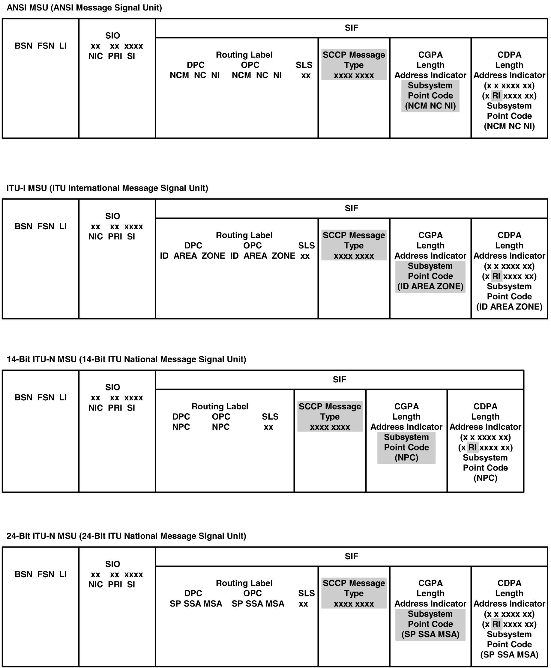
The allowed calling party address (CGPA) screen is used to screen SCCP messages from another network. The gray shaded areas in Figure 6-4 shows the fields of the SS7 message that are checked by the CGPA screening function. The screening reference contains a list of point codes and subsystem number combinations.
Gateway Screening Actions
If a match is not found, the message is discarded.
If a match is found, the nsfi is examined to determine the next step in the screening process. If the nsfi value is any value other than stop, the next screening reference (nsr) is identified and the screening process continues to the next screen identified by the nsfi and nsr parameter values.
nsfi is equal to stop, the screening process stops and the message is processed. If a gateway screening stop action set is specified with the screen, shown by the actname parameter value, the message is processed according to the gateway screening stop actions that are assigned to the gateway screening stop action set.
- If the
rdct(redirect) gateway screening stop action is specified,the message is diverted from the original destination and sent to another destination with the Database Transport Access feature, specified by global title translation, for further processing. - If the
cncfgateway screening stop action is specified, the PIP parameter in the incoming ISUP IAM message is converted to the GN parameter. The GN parameter in the incoming ISUP IAM message is converted to the PIP parameter. The message is then sent to the node specified by the DPC in the routing label in the message. For more information on the Calling Name Conversion Facility feature, see Calling Name Conversion Facility (CNCF) Configuration. - If the
tlnpgateway screening stop action is specified, ISUP IAMs that pass gateway screening are processed either by the ISUP NP with EPAP feature (if the ISUP NP with EPAP feature is enabled and turned on) or by the Triggerless LNP feature (if the Triggerless LNP feature is turned on). The ISUP NP with EPAP feature is discussed in more detail in G-Port User's Guide. The Triggerless LNP feature is discussed in more detail in ELAP Administration and LNP Feature Activation Guide. - If the
tinpgateway screening stop action is specified, ISUP IAMs that pass gateway screening are intercepted by the Triggerless ISUP based Number Portability (TINP) feature and converted to include the routing number (RN) if the call is to a ported number. The TINP feature is discussed in more detail in G-Port User's Guide. - If the
tif,tif2, ortif3gateway screening stop actions are specified, TIF processing is applied to the message. - If the
sccpgateway screening stop action is specified, MTP routed SCCP UDT/XUDT are forwarded to the service modules for further processing.
Allowed CGPA Screening Actions
Any MSU that does not contain a service indicator of 3 in the SIO field and does not contain the SCCP message types 9, 10, 17, or 18 and reaches this screen in the gateway screening process automatically passes gateway screening and is allowed into the EAGLE.
The value of the
nsfi parameter is based on the value of
the routing indicator (ri) parameter.
Table 6-1
through
Figure 6-3
show the valid combinations of
nsfi values and routing indicator
values.
Table 6-1 Valid Parameter Combinations for the Allowed CGPA Screening Function
| Routing Indicator (RI) Values | Nest Screening Function Identifier (NSFI) Values |
|---|---|
| GT | TT |
| DPC | CDPA |
| * (asterisk) | TT, CDPA |
Figure 6-1 shows the screening actions of the allowed CGPA screen.
Figure 6-1 Allowed CGPA Screening Actions - Sheet 1 of 3
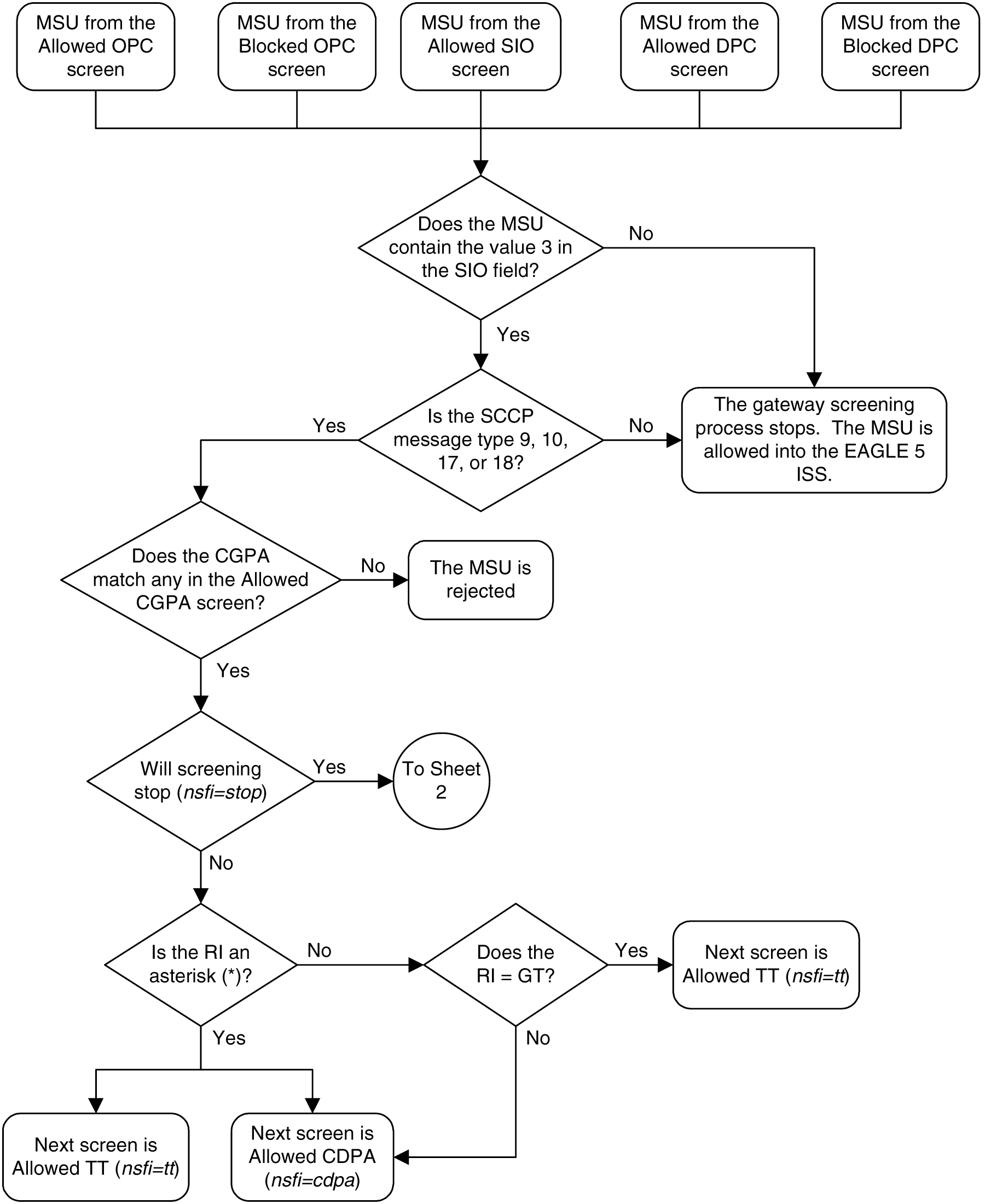
Figure 6-2 Allowed CGPA Screening Actions - Sheet 2 of 3

Figure 6-3 Allowed CGPA Screening Actions - Sheet 3 of 3

Figure 6-4 Allowed Calling Party Address Screening Function
Adding an Allowed Calling Party Address Screen
This procedure is used to add an allowed calling party
address (CGPA) screen to the database using the
ent-scr-cgpa command. The parameters
used by the
ent-scr-cgpa command are shown in the
Gateway Screening Attributes
section. The general rules that apply to configuring gateway screening entities
are shown in the
Gateway Screening Configuration
section.
The examples in this procedure are used to add the allowed CGPA screen data shown in Table 6-2 and based on the example configurations shown in Figure 2-3 through Figure 2-5.
Table 6-2 Example Gateway Screening Allowed CGPA Configuration Table
| Screening Reference | ZONE | AREA | ID | SN | RI | SCCPMT | NSFI | NSR |
|---|---|---|---|---|---|---|---|---|
| gw11 | 7 | 100 | 4 | 254 | * | 010 | cdpa | gw15 |
| Screening Reference | NI | NC | NCM | SSN | RI | SCCPMT | NSFI | NSR |
|---|---|---|---|---|---|---|---|---|
| gw13 | 007 | 007 | 007 | 250 | gt | 017 | tt | gw16 |
| gw14 | 006 | 006 | 006 | 253 | dpc | 009 | cdpa | gw17 |
Note:
If you using multiple-part ITU national point codes with gateway screening, see the 14-Bit ITU National Point Code Formats section.The allowed CGPA screen can reference one of the following screens.
- Allowed TT
- Allowed CDPA
Verifying the Gateway Screening Configuration
Enter the following commands to verify that these screens are in the database.
rtrv-scr-tt:all=yesrtrv-scr-cdpa:all=yes
Gateway Screening Configuration Procedures
If the desired screen is not in the database, perform one of the following procedures to add the desired screen to the database or change an existing screen in the database.
- Adding an Allowed Translation Type Screen
- Adding an Allowed Called Party Address Screen
- Changing an Allowed Translation Type Screen
- Changing an Allowed Called Party Address Screen
Specifying a Range of Values
A range of values can be specified for the point code
parameters
ni,
nc, or
ncm.
If a range of values is specified for any of these parameters, and the value of the other parameters match existing values for the screening reference name, the range of values for the point code parameter cannot include any values for that parameter that are currently provisioned for the screening reference name.
For example, screening reference name
scr1 contains these entries:
SR    NI       NC       NCM      SSN      RI   SCCPMT   NSFI    NSR/ACT
SCR1  240      001      010      012      DPC  009      STOP    ------
SCR1  241      010      020      *        GT   017      TT      SCR1
Another entry for screening reference
scr1 with the
ni value of 240 and the
nc value of 001 cannot be specified if
the range of values for the
ncm parameter includes the value 010.
The ANSI point code parameter values can be specified as
a single value, a range of values, or with an asterisk (*). The asterisk
specifies all possible values for the
ni,
nc, and
ncm parameters.
Table 6-3
shows the valid combinations of these parameter values.
Table 6-3 Valid Value Combinations for ANSI Point Code Parameters
| NI | NC | NCM |
|---|---|---|
| Single Value | Single Value | Single Value |
| Single Value | Single Value | Range of Values |
| Single Value | Single Value | Asterisk |
| Single Value | Range of Values | Asterisk |
| Single Value | Asterisk | Asterisk |
| Range of Values | Asterisk | Asterisk |
| Asterisk | Asterisk | Asterisk |
A range of values can also be specified for an ITU-I or 24-bit ITU-N point code parameter using a combination of asterisks (*) and single values for the point code parameters. Table 6-4 shows the valid combinations of the ITU-I parameter values. Table 6-5 shows the valid combinations of the 24-bit ITU-N parameter values.
Table 6-4 Valid Value Combinations for ITU-I Point Code Parameters
| ZONE | AREA | ID |
|---|---|---|
| Single Value | Single Value | Single Value |
| Single Value | Single Value | Asterisk |
| Single Value | Asterisk | Asterisk |
| Asterisk | Asterisk | Asterisk |
Table 6-5 Valid Value Combinations for 24-Bit ITU-N Point Code Parameters
| MSA | SSA | SP |
|---|---|---|
| Single Value | Single Value | Single Value |
| Single Value | Single Value | Asterisk |
| Single Value | Asterisk | Asterisk |
| Asterisk | Asterisk | Asterisk |
Figure 6-5 Add an Allowed Calling Party Address Screen - Sheet 1 of 4
Figure 6-6 Add an Allowed Calling Party Address Screen - Sheet 2 of 4
Figure 6-7 Add an Allowed Calling Party Address Screen - Sheet 3 of 4
Figure 6-8 Add an Allowed Calling Party Address Screen - Sheet 4 of 4
Removing an Allowed Calling Party Address Screen
This procedure is used to remove an allowed calling
party address (CGPA) screen from the database using the
dlt-scr-cgpa command. The parameters
used by the
dlt-scr-cgpa command are shown in the
Gateway Screening Attributes
section. The general rules that apply to configuring gateway screening entities
are shown in the
Gateway Screening Configuration
section.
The example in this procedure removes the allowed CGPA
screen
gw14 from the database.
Note:
If you using multiple-part ITU national point codes with gateway screening, see the 14-Bit ITU National Point Code Formats section.The allowed CGPA screen can be referenced by one of the following screens.
- Allowed OPC
- Blocked OPC
- Allowed SIO
- Allowed DPC
- Blocked DPC
Verifying the Gateway Screening Configuration
Enter the following commands to verify that none of these screens reference the allowed CGPA screen being removed from the database.
-
rtrv-scr-opc:nsfi=cgpa -
rtrv-scr-blkopc:nsfi=cgpa -
rtrv-scr-sio:nsfi=cgpa -
rtrv-scr-dpc:nsfi=cgpa -
rtrv-scr-blkdpc:nsfi=cgpa
Gateway Screening Configuration Procedures
To change the NSFI of any of these screens, perform one of these procedures.
Figure 6-9 Remove an Allowed Calling Party Address Screen - Sheet 1 of 2
Figure 6-10 Remove an Allowed Calling Party Address Screen - Sheet 1 of 2
Changing an Allowed Calling Party Address Screen
This procedure is used to change the attributes of an
allowed calling party address (CGPA) screen in the database using the
chg-scr-cgpa command. The parameters
used by the
chg-scr-cgpa command are shown in the
Gateway Screening Attributes
section. The general rules that apply to configuring gateway screening entities
are shown in the
Gateway Screening Configuration
section.
The example in this procedure is used to change the
point code 003-003-003 for the allowed CGPA screen
gw14 to 230-230-230 and change the
subsystem number from 253 to 150.
Note:
If you using multiple-part ITU national point codes with gateway screening, see the 14-Bit ITU National Point Code Formats section.The allowed CGPA screen can reference one of the following screens.
- Allowed TT
- Allowed CDPA
Verifying the Gateway Screening Configuration
Enter the following commands to verify that these screens are in the database.
rtrv-scr-tt:all=yesrtrv-scr-cdpa:all=yes
Gateway Screening Configuration Procedures
If the desired screen is not in the database, perform one of these procedures to add the desired screen to the database or change an existing screen in the database.
- Adding an Allowed Translation Type Screen
- Adding an Allowed Called Party Address Screen
- Changing an Allowed Translation Type Screen
- Changing an Allowed Called Party Address Screen
Specifying a Range of Values
A range of values can be specified for the point code
parameters
ni,
nc, or
ncm.
If a range of values is specified for any of these parameters, and the value of the other parameters match existing values for the screening reference name, the range of values for the point code parameter cannot include any values for that parameter that are currently provisioned for the screening reference name.
For example, screening reference name
scr1 contains these entries:
SR    NI       NC       NCM      SSN      RI   SCCPMT   NSFI    NSR/ACT
SCR1  240      001      010      012      DPC  009      STOP    ------
SCR1  241      010      020      *        GT   017      TT      SCR1
Another entry for screening reference
scr1 with the
ni value of 240 and the
nc value of 001 cannot be specified if
the range of values for the
ncm parameter includes the value 010.
The ANSI point code parameter values can be specified as
a single value, a range of values, or with an asterisk (*). The asterisk
specifies all possible values for the
ni,
nc, and
ncm parameters.
Table 6-6
shows the valid combinations of these parameter values.
Table 6-6 Valid Value Combinations for ANSI Point Code Parameters
| NI | NC | NCM |
|---|---|---|
| Single Value | Single Value | Single Value |
| Single Value | Single Value | Range of Values |
| Single Value | Single Value | Asterisk |
| Single Value | Range of Values | Asterisk |
| Single Value | Asterisk | Asterisk |
| Range of Values | Asterisk | Asterisk |
| Asterisk | Asterisk | Asterisk |
A range of values can also be specified for an ITU-I or 24-bit ITU-N point code parameter using a combination of asterisks (*) and single values for the point code parameters. Table 6-7 shows the valid combinations of the ITU-I parameter values. Table 6-8 shows the valid combinations of the 24-bit ITU-N parameter values.
Table 6-7 Valid Value Combinations for ITU-I Point Code Parameters
| ZONE | AREA | ID |
|---|---|---|
| Single Value | Single Value | Single Value |
| Single Value | Single Value | Asterisk |
| Single Value | Asterisk | Asterisk |
| Asterisk | Asterisk | Asterisk |
Table 6-8 Valid Value Combinations for 24-Bit ITU-N Point Code Parameters
| MSA | SSA | SP |
|---|---|---|
| Single Value | Single Value | Single Value |
| Single Value | Single Value | Asterisk |
| Single Value | Asterisk | Asterisk |
| Asterisk | Asterisk | Asterisk |
Figure 6-11 Change an Allowed Calling Party Address Screen - Sheet 1 of 5
Figure 6-12 Change an Allowed Calling Party Address Screen - Sheet 2 of 5
Figure 6-13 Change an Allowed Calling Party Address Screen - Sheet 3 of 5
Figure 6-14 Change an Allowed Calling Party Address Screen - Sheet 4 of 5
Figure 6-15 Change an Allowed Calling Party Address Screen - Sheet 5 of 5