2 Global Title Translation (GTT) Overview
Chapter 2, Global Title Translation (GTT) Overview, describes the Global Title Translation feature and the procedures common to both the Global Title Translation (GTT) and Enhanced Global Title Translation (EGTT) features. This chapter also describes the features shown in the Overview section.
Introduction
- Variable-length Global Title Translation
- Advanced GT Modification
- Intermediate GTT Load Sharing
- ANSI/ITU SCCP Conversion
- Flexible GTT Load Sharing
- Origin-Based SCCP Routing
- Hex Digit Support for GTT
- Weighted GTT Load Sharing
- Transaction-Based GTT Load Sharing
- SCCP Loop Detection
- Flexible Linkset Optional Based Routing
- TCAP Opcode Based Routing
- GTT Actions
- XUDT UDT Conversion
This chapter also contains the procedures that are common to configuring either the Global Title Translation (GTT) feature or the Enhanced Global Title Translation (EGTT) feature. To find out about the differences between Global Title Translation feature and the Enhanced Global Title Translation feature, refer to the Upgrading from Global Title Translation (GTT) to Enhanced Global Title Translation (EGTT) section.
Global Title Translation Feature
The Global Title Translation (GTT) feature is designed for the signaling connection control part (SCCP) of the SS7 protocol. The EAGLE uses this feature to determine to which service database to send the query message when a Message Signaling Unit (MSU) enters the EAGLE and more information is needed to route the MSU.
If an MSU enters the EAGLE and more information is needed to route the MSU, the SCCP of the SS7 protocol sends a query to a service database to obtain the information. The EAGLE uses the GTT feature for the SCCP to determine which service database to send the query messages to. These service databases are also used to verify calling card numbers and credit card numbers. The service databases are identified in the SS7 network by a point code and a subsystem number.
The GTT feature uses global title address (GTA) information to determine the destination of the MSU. The translation type (TT) indicates which global title translation table is used to determine the routing to a particular service database. Each global title translation table includes the point code (pc) of the node containing the service database, the subsystem number (ssn) identifying the service database on that node, and a routing indicator (ri). The routing indicator determines if further global title translations are required. GTA and TT are contained in the called party address (CDPA) field of the MSU.
The global title translation feature changes the destination point code and the origination point code in the routing label. The global title information is not altered. The routing label is changed to indicate the new destination point code retrieved from the global title translation and the origination point code is set to the EAGLE’s point code.
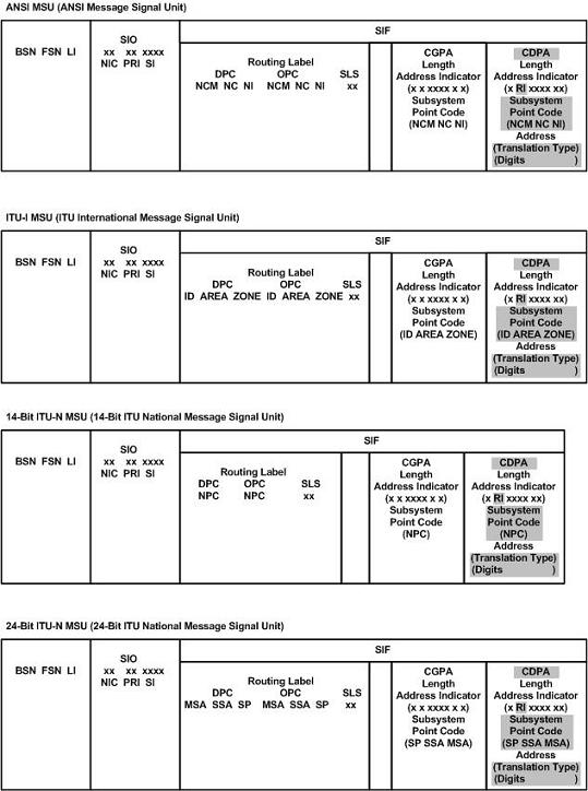
Depending on how the global title translation data is configured, the routing indicator, the subsystem number, or the translation type in the called party address may also be changed by the global title translation feature. The gray shaded areas in Figure 2-1 show the message fields affected by global title translation.
Figure 2-1 ANSI and ITU MSU Fields affected by the Global Title Translation Feature
The GTT feature allows global title translation on global title addresses of fixed length. There are three optional add-on features that enhance the functionality of the global title translation feature:
- The Variable-length Global Title Translation feature (VGTT) feature allows global title translation on global title addresses of varying length. For more information on this feature, refer to the Variable-length Global Title Translation Feature section.
- The Advanced GT Modification feature allows the EAGLE to modify other fields of an MSU in addition to the translation type when the MSU requires further global title translation and the translation type is to be replaced. For more information about this feature, refer to the Advanced GT Modification Feature section.
- The ANSI/ITU SCCP Conversion Feature converts SCCP messages between the ANSI and ITU formats. For more information about this feature, refer to the ANSI/ITU SCCP Conversion Featuresection.
The EAGLE supports:
- 269,999, 400,000, or 1,000,000 global title translations. The system default is 269,999 global title translations. This quantity can be increased to 400,000 by enabling the feature access key for part number 893-0061-01, or to 1,000,000 by enabling the feature access key for part number 893-0061-10. For more information on enabling these feature access keys, refer to the Enabling the XGTT Table Expansion Feature procedure.
- A maximum of 200,000 global title translations assigned to a translation type.
- 512 translation types, 256 translation types for ANSI MSUs, and 256 translation types for ITU MSUs.
- 1024, 2000, or 3000 remote point codes (mated applications), with up to 10 subsystems at each point code. The system default is 1024 mated applications. This quantity can be increased to 2000 by enabling the feature access key for part number 893-0077-01, or to 3000 by enabling the feature access key for part number 893-0077-10. For more information on enabling these feature access keys, refer to the Enabling the XMAP Table Expansion Feature procedure.
The GTT feature requires one of the following cards:
- Database Services Module (DSM) (Refers to the E5-SM4G or E5-SM8G-B card)
- SLIC card
For more information on these cards, refer to the Adding a Service Module procedure or to Hardware Reference.
Enhanced Global Title Translation Feature
The Enhanced Global Title Translation (EGTT) feature is designed for the signaling connection control part (SCCP) of the SS7 protocol. The EAGLE uses this feature to determine to which service database to send the query message when a Message Signaling Unit (MSU) enters the EAGLE and more information is needed to route the MSU.
If an MSU enters the EAGLE and more information is needed to route the MSU, the SCCP of the SS7 protocol sends a query to a service database to obtain the information. The EAGLE uses the EGTT feature for the SCCP to determine which service database to send the query messages to. The service databases are identified in the SS7 network by a point code and a subsystem number.
The EGTT feature uses global title information (GTI) to determine the destination of the MSU. The EAGLE supports ANSI GTI format 2 and ITU GTI formats 2 and 4. The GTI is contained in the called party address (CDPA) field of the MSU. For ITU GTI format 4, the GTI is made up of the Numbering Plan (NP), Nature of Address Indicator (NAI), and Translation Type (TT) selectors.
The EGTT feature allows global title translation on global title addresses of fixed length. There are three optional add-on features that enhance the functionality of the enhanced global title translation feature:
- The Variable-length Global Title Translation feature (VGTT), allows global title translation on global title addresses of varying length. For more information on this feature, refer to the Variable-length Global Title Translation Featuresection.
- The Advanced GT Modification feature allows the EAGLE to modify other fields of an MSU in addition to the translation type when the MSU requires further global title translation and the translation type is to be replaced. For more information about this feature, refer to the section Advanced GT Modification Feature.
- The ANSI/ITU SCCP Conversion Feature converts SCCP messages between the ANSI and ITU formats. For more information about this feature, refer to the ANSI/ITU SCCP Conversion Feature section.
The EGTT feature requires one of the following cards:
- EAGLE 5-Service Module 8GB (E5-SM8G-B) or SLIC
For more information on these cards, refer to the Adding a Service Module procedure or to Hardware Reference.
Inclusion of SSN in the CDPA
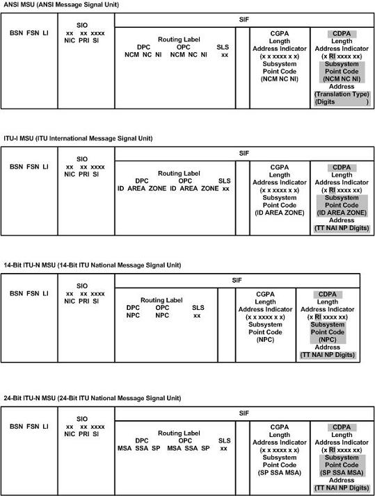
When the obtained translation data contains a subsystem, the translated SSN is placed in the SCCP CDPA before the message is sent to the next node. However, when no SSN is present in the CDPA, this insertion applies to ITU messages only. ANSI messages that do not contain an SSN in the CDPA will be rejected. The gray shaded areas in Figure 2-2 show the message fields affected by enhanced global title translation.
Figure 2-2 ANSI and ITU MSU Fields affected by the Enhanced Global Title Translation Feature
Inclusion of OPC in the CGPA
When an ITU unitdata (UDT) message does not have a point code (PC) present in the CGPA, and the CGPA route indicator (RI) is set to Route on SSN, the EGTT feature will insert the OPC from the Message Transfer Part (MTP) routing label into the CGPA before sending the message to the next node. The insertion does not apply to ANSI GTT processing.
Deletion of GT
The EGTT feature allows a Global Title (GT) in the CDPA
to be deleted. For example, when the result of a GTT performed by the EAGLE is
set to “Route on SSN”, there may be some end nodes that do not want to receive
the GT information in the CDPA. The enhancement provides an option on a per
translation basis (for both ANSI and ITU) to allow the GT to be deleted
(ent-gta:gta=000:ri=ssn:ccgt=yes command). The
option is not valid when the result of the GT is the EAGLE’s point code and
local SSN.
New Commands
The EGTT feature introduces three new command sets:
- GTTSET commands
ENT-GTTSET– Enter GTT SetCHG-GTTSET– Change GTT SetDLT-GTTSET– Delete GTT SetRTRV-GTTSET– Retrieve GTT Set
- GTTSEL commands
ENT-GTTSEL– Enter GTT SelectorCHG-GTTSEL– Change GTT SelectorDLT-GTTSEL– Delete GTT SelectorRTRV-GTTSEL– Retrieve GTT Selector
- GTA commands
ENT-GTA– Enter Global Title AddressCHG-GTA– Change Global Title AddressDLT-GTA– Delete Global Title AddressRTRV-GTA– Retrieve Global Title Address
GTT Set Commands
The GTT Set commands are used to provision new sets of GTTs, linking GTT Selector (-GTTSEL) and Global Title Address (-GTA) commands. This set of commands provides greater flexibility when provisioning the type of messages that require Global Title Translation. There are no SEAS equivalents for these commands.
GTT Selector Commands
The GTT Selector commands are used to provision new selectors for global title translation. Together with the GTT Set commands, these commands replace the Translation Type (-TT) commands, providing greater flexibility when provisioning the type of messages that require Global Title Translation. There are no SEAS equivalents for these commands.
GTA Commands
GTA commands are used to provision GTTs using the new selectors for GTT.
The EAGLE supports the following:
- Maximum of 950 GTT sets.
- Maximum of 200,000 global title addresses per GTT set.
- 269,999, 400,000, or 1,000,000 global title addresses. The system default is 269,999 global title addresses. This quantity can be increased to 400,000 by enabling the feature access key for part number 893-0061-01, or to 1,000,000 by enabling the feature access key for part number 893-0061-10. For more information on enabling these feature access keys, refer to the Enabling the XGTT Table Expansion Feature procedure.
- Maximum of 100,000 GTT selectors.
- 1024, 2000, or 3000 remote point codes (mated applications), with up to 10 subsystems at each point code. The system default is 1024 mated applications. This quantity can be increased to 2000 by enabling the feature access key for part number 893-0077-01, or to 3000 by enabling the feature access key for part number 893-0077-10. For more information on enabling these feature access keys, refer to the Enabling the XMAP Table Expansion Feature procedure.
Variable-length Global Title Translation Feature
A translation type or GTT set can contain global title
addresses of varying length. If the Variable-length Global Title Translation
(VGTT) feature is turned on with the
chg-feat command, a translation type or
GTT set contain up to 10 different length global title addresses. If the
Support for 16 GTT Lengths in VGTT feature is enabled and turned on with the
enable-ctrl-feat and
chg-ctrl-feat commands, a translation
type or GTT set can contain up to 16 different length global title addresses.
The Support for 16 GTT Lengths in VGTT feature cannot be enabled and turned on
unless the VGTT feature is turned on.
The length of the global title address is only limited by
the range of values for the
gta and
egta parameters of either the
ent-gtt and
chg-gtt commands, if only the GTT
feature is turned on, or the
ent-gta and
chg-gta commands, if the EGTT feature is
turned on, and by the global title addresses already assigned to the
translation type or GTT set. The length of a global title address is from 1 to
21 digits, or 1 to 21 hexadecimal digits if the Hex Digit Support for GTT
feature is enabled. The
ndgt parameter of the
ent-tt or
ent-gttset command has no effect on the
length of the global title address and cannot be used. If the
ndgt parameter is specified with the
ent-tt or
ent-gttset command and the VGTT feature
is on or the Support for 16 GTT Lengths in VGTT feature is enabled and turned
on, the
ent-tt or
ent-gttset command is rejected with this
message.
E4011 Cmd Rej: NDGT parameter is
		  invalid for VGTT
As global title addresses of different lengths are
assigned to a specific translation type, these lengths are displayed in the
NDGT field of the
rtrv-tt command output, as shown in the
following example.
rlghncxa03w 09-05-25 09:57:31 GMT  EAGLE5 41.0.0
TYPEA      TTN        NDGT
1          lidb       6, 12, 15
2          c800       10
3          d700       6

ALIAS      TYPEA
50         3
65         3

TYPEI      TTN        NDGT
105        itudb      8

ALIAS      TYPEI
7          105

TYPEN      TTN        NDGT
120        dbitu      7

ALIAS      TYPEN
8          120
If the global title addresses are assigned to a GTT set,
these lengths are displayed in the
NDGT field of the
rtrv-gttset command output, as shown in
the following example.
rlghncxa03w 09-07-07 00:30:31 GMT EAGLE5 41.1.0
GTTSN     NETDOM  NDGT
lidb      ansi    3, 7, 10
t800      ansi    6
si000     itu     15
imsi      itu     15
abcd1234  itu     12

GTT-SET table is (5 of 2000) 1% full.
In the
rtrv-tt output example, the ANSI
translation type 1 contains three different length global title addresses;
global title addresses containing 6 digits, 12 digits, and 15 digits.
In the
rtrv-gttset example, the GTT set
lidb contains three different length
global title addresses; global title addresses containing 3 digits, 7 digits,
and 10 digits.
When the VGTT feature is on, and the last global title
address of a particular length is deleted for the specified translation type or
GTT set, then that length is no longer supported. That length is not displayed
in the
NDGT field of the
rtrv-tt or the
rtrv-gttset output. For example, if the
last 6-digit global title address is deleted from ANSI translation type 1 (from
the previous example), the
NDGT field of the
rtrv-tt command shows only the numbers
12 and 15 in the
NDGT field indicating that ANSI
translation type 1 contains only 12- and 15-digit global title addresses. If
the last 7-digit global title address is deleted from GTT set
lidb (from the previous example), the
NDGT field of the
rtrv-gttset command shows only the
numbers three and 10 in the
NDGT field indicating that GTT set
lidb contains only 3- and 10-digit
global title addresses.
If the translation type has the maximum number of
different length global title addresses assigned to it, and another global
title address is specified for the translation type, the length of the global
title address being added to the translation type must be the same as one of
the lengths already assigned to the translation type. If the length of the
global title address is not one of the lengths shown in the
rtrv-tt output, the
ent-gtt command is rejected with this
message.
E4007 Cmd Rej: Exceeding max GTA
		  Lengths supported per TT
If the GTT set has the maximum number of different
length global title addresses assigned to it, and another global title address
is specified for the GTT set, the length of the global title address being
added to the GTT set must be the same as one of the lengths already assigned to
the GTT set. If the length of the global title address is not one of the
lengths shown in the
rtrv-gttset output, the
ent-gta command is rejected with this
message.
E4008 Cmd Rej: Exceeding max
		  GTA Lengths supported per GTTSET
If the translation type or GTT set has less than the maximum number of different length global title addresses assigned to it, and another global title address is specified for the translation type or GTT set, the length of the global title address can be from one to 21 digits and does not have to match the length of the other global title addresses assigned to the translation type or the GTT set.
If the VGTT feature is off, shown the entry
VGTT = off in the
rtrv-feat output, the global title
address length must be equal to the number of digits specified by the given
translation type or GTT set. The length of the global title address can be
verified with the
rtrv-tt or
rtrv-gttset command.
The VGTT and the Support for 16 GTT Lengths in VGTT features require that a service module is installed in the EAGLE. Adding a Service Module shows the type of service modules that can be used depending on which features are on or enabled.
Advanced GT Modification Feature
This feature allows the EAGLE to modify other fields of an MSU in addition to the translation type, destination point code, called party point code, called party SSN, routing indicator, numbering plan, and nature of address indicator when the MSU requires further global title translation and the translation type is to be replaced.
The numbering plan, nature of address indicator, and the prefix or suffix digits, in the called party address or calling party address portion of outbound MSUs can be changed with this feature to make the MSU more compatible with the network that the MSU is being sent to and to ensure that the MSU is routed correctly. These changes are made after the global title translation process, but before the MSU is routed to its destination.
This feature requires that service modules are installed in the EAGLE. Adding a Service Module shows the type of service modules that can be used depending on which features are on or enabled.
For the EAGLE to be able to make these changes to the
called party address or calling party address portion of the MSU, the one of
the Advanced GT Modification features shown in the following list must be
enabled with the
enable-ctrl-feat command.
- 893021801 - AMGTT - provides GT modification to both the called party address and the calling party address of SCCP messages. This part number can be specified only if no Advanced GT Modification feature is currently enabled.
- 893021802 - AMGTT CdPA Only - provides GT modification
to the called party address of SCCP messages only. This feature and its part
number is shown in the
rtrv-ctrl-featoutput only if the MGTT feature from previous releases was turned on when the Eagle was upgraded to the release containing the Advanced GT Modification feature. This part number cannot be specified with theenable-ctrl-featcommand. - 893021803 - AMGTT CgPA Upgrade - provides GT modification to the calling party address and called party address of SCCP messages. This part number can be specified only if the AMGTT CdPA Only feature (part number 893021802) is enabled.
Perform the Activating the Advanced GT Modification Feature procedure to enable the Advanced GT Modification feature.
After the Advanced GT Modification feature has been enabled, the parameters shown in this list are used to modify the calling party address or called party address of the SCCP message.
gtmodid– The name of the GT modification identifierntt– The new translation type. None of the Advanced GT Modification features have to be enabled to create an entry in the GT modification table that contains only thenttparameter value.nnp– The new numbering plannnai– The new nature of address indicatornpdd– The number of digits to be deleted from the beginning of the Global Title Address digits (the prefix digits)npds– The digits that are being substituted for the prefix digitsnsdd– The number of digits to be deleted from the end of the Global Title Address digits (the suffix digits)nsds– The digits that are being substituted for the suffix digitscgpassn– The calling party subsystem numbergt0fill– Specifies whether the final 0 of the global title address is considered a valid digit in the global title address or as a filler during the GT modification process when going from GTI=2 to GTI=4. If the final 0 is considered as a filler, then it is ignored during the GT modification process. This parameter has two values,onoroff. If thegt0fillvalue ison, the final 0 in the global title address is a filler. If thegt0fillvalue is off, the final 0 in the global title address is a valid digit.ngti– The new global title indicator valueprecd– Specifies whether the prefix or suffix digits take precedence when modifying the received global title address. This parameter can be specified only when thenpdd/npdsand thensdd/nsdsparameters are specified. This parameter has two values,pfxandsfx. When theprecdvalue ispfx, the prefix digits (npdd/npdsvalues) are processed before the suffix digits (nsdd/nsds) values.When theprecdvalue issfx, the suffix digits (nsdd/nsdsvalues) are processed before the prefix digits (npdd/npds) valuescggtmod- The calling party GT modification indicator. This parameter specifies whether or not calling party global title modification is required. This parameter can be specified only if the AMGTT or AMGTT CgPA Upgrade feature is enabled. Thecggtmodparameter can also be specified for when provisioning a linkset to indicate that calling party global title modification is required for SCCP traffic on the linkset. This parameter is configured with theent-gtt,chg-gtt,ent-gta, orchg-gtacommands.
cggtmod parameter, are configured as an
entry in the in the GT modification table using either the
ent-gtmod or
chg-gtmod commands. Each entry in the GT
modification table is identified by the
gtmodid parameter. The EAGLE can contain
100,000 GT modification identifier entries. Each entry is referenced in the
GTT, GTA, and GTT actions tables. Perform one of these procedures to configure
these parameters.
To configure the
cggtmod parameter, perform one of these
procedures.
Intermediate GTT Load Sharing Feature
This feature allows GTT traffic between multiple nodes to be load shared when intermediate global title translation (routing indicator in the message is GT) is being performed. A mated relay node (MRN) group is provisioned in the database to identify the nodes that the traffic is load shared with, and the type of routing, either dominant, load sharing, or combined dominant/load sharing. This load sharing is performed after intermediate global title translation is performed on the message. For more information, refer to Provisioning MRN Entries.
ANSI/ITU SCCP Conversion Feature
Since some ANSI and ITU SCCP parameters are incompatible in format or coding, this feature provides a method for the EAGLE to convert these SCCP parameters in UDT, UDTS, XUDT, and XUDTS messages. Other types of SCCP messages (for example, XUDTS) are not supported and are discarded.
A specialized SCCP/TCAP conversion, introduced in EAGLE release 22.2 and used only in the Korean market, does not support this feature. The ANSI/ITU SCCP Conversion feature cannot be used with the EAGLE release 22.2 SCCP and TCAP Conversion features.
The ANSI/ITU SCCP Conversion feature provides a generic capability to correctly format and decode/encode these SCCP messages:
-
UDT, UDTS, XUDT, and XUDTS messages. UDT and UDTS messages include SCMG messages, which are a specialized form of UDT messages.
-
MTP routed SCCP messages.
-
GT routed SCCP messages.
This feature also provides SCCP management (SCMG) across network type boundaries. For example, concerned signaling point codes for a mated application may be of a different network type than the primary point code of the mated application.
The ANSI/ITU SCCP Conversion is optional for ITU-X to ITU-Y domain crossing, where X and Y are different variants of ITU domains (ITU-I, ITU-N, ITU-I Spare and ITU-N Spare).
Advanced GT Modification
The Advanced GT Modification feature allows the deletion or substitution of digits from the beginning (prefix digit modification) or the end (suffix digit modification) of the global title address in either the called party address or the calling party address of the MSU. Prefix and suffix digit modifications are performed based on the prefix and suffix digit modification parameter values that are contained in the GT modification identifier that is assigned to the GTT, GTA, or GTT Actions entry. If the Advanced GT Modification feature is enabled, each GTT, GTA, or GTT Actions entry can specify either prefix digit modification, suffix digit modification, or both prefix and suffix digit modification. Refer to the Advanced GT Modification Feature section for more information on the Advanced GT Modification feature.
ANSI/ITU SCCP Conversion Feature Configuration
This feature requires that service modules are present in the EAGLE. Adding a Service Module shows the type of service modules that can be used depending on which features are on or enabled.
The parameter CNVCLGITU in SCCPOPTS makes the SCCP CGPA conversion optional for ITU-I to ITU-N domain crossing. The default value of this parameter is OFF when ANSI/ITU SCCP Conversion feature is turned on. If the feature is already ON, and the system is upgraded to Eagle 45.0, the default value is ON.
With the introduction of the parameter
cgpcaction under the
ent/chg-gta commands, CGPCACTION in
GTA is applied regardless of whether the domain crossing was determined by GTT
or not. Refer to
Commands User's Guide for more details and
options.
ITU-I to ITU-N SCCP CgPA conversion is optional for GTT related features only (GTT, GTT Actions, GTMOD and MAP SCRN). It is not applicable for services and subsystems that perform GTT on CgPA (GPORT, EIR, IDPR)
The ANSI/ITU SCCP Conversion feature must be enabled with
the
enable-ctrl-feat command, and turned on
with the
chg-ctrl-feat command. Perform the
Activating the ANSI/ITU SCCP Conversion Feature
procedure to enable and turn on the ANSI/ITU SCCP Conversion feature.
The concerned signaling point code (CSPC) group
configuration has been changed to allow CSPC groups to contain ANSI (pc/pca), ITU-I or ITU-I spare (pci), and either 14-bit ITU-N or 14-bit ITU-N spare
(pcn), or 24-bit ITU-N (pcn24) point codes. A CSPC group cannot contain both
14-bit and 24-bit ITU-N point codes. Concerned signaling point code groups are
configured in the
Adding a Concerned Signaling Point Code
procedure.
The format of the point codes in the CSPC group assigned
to a mated application, specified with the
grp parameter, must be the same as the
primary point code specified with the
ent-map or
chg-map commands only if the ANSI/ITU
SCCP Conversion feature is not enabled. If the ANSI/ITU SCCP Conversion feature
is enabled, the CSPC group may contain a mixture of point code types, and the
network type of the CSPC group can be different from the network type of the
primary point code of the mated application. Mated applications are configured
in these procedures.
- Provisioning a Solitary Mated Application
- Provisioning a Dominant Mated Application
- Provisioning a Load Shared Mated Application
- Provisioning a Combined Dominant/Load Shared Mated Application
- Changing the Attributes of a Mated Application.
The conversion of ANSI and ITU SCCP messages is performed according to the options in the STP Options table, and by the entries contained in the default GT conversion table.
These options in the STP Options table control how this feature works.
:cnvcgda – The CGPA point
code in ANSI SCCP messages are discarded if the point code or alias point code
of the destination network type is not defined.
:cnvcgdi – The CGPA point
code in ITU-I SCCP messages are discarded if the point code or alias point code
of the destination network type is not defined.
:cnvcgdn – The CGPA point
code in ITU-N SCCP messages are discarded if the point code or alias point code
of the destination network type is not defined.
:cnvcgdn24 – The CGPA
point code in ITU-N24 SCCP messages are discarded if the point code or alias
point code of the destination network type is not defined.
:cnvclgitu – Allows for ITU-X to ITU-Y
SCCP CGPA Conversion.
:gtcnvdflt – SCCP
messages are routed using system defaults when an appropriate entry is not
found in the Default GT Conversion Table.
The values for these options are either
yes or
no. If these options are set to
yes, the actions defined by these
options will be performed. These options are configured using the
chg-stpopts command in the
Changing the ANSI/ITU SCCP Conversion Options
procedure.
Note:
If the value of thecnvcgda,
cnvcgdi, or
cnvcgdn options is
no, and the calling party address of
the MSU cannot be converted when the MSU is processed, then the MSU is
discarded.
The Default GT Conversion Table contains the following items:
- The direction that the conversion takes place: ANSI to ITU, ITU to ANSI, or both directions.
- The global title indicator types being converted.
- ANSI GTI type 2 to ITU GTI type 2
- ANSI GTI type 2 to ITU GTI type 4
- The ANSI translation type
- The ITU translation type
- The numbering plan
- The nature of address indicator
The Default GT Conversion Table also provides for the
provisioning of prefix or suffix address digit modification (refer to the
Advanced
GT Modification section. The Default GT Conversion Table is configured
using either the
ent-gtcnv command to add new entries to
the Default GT Conversion Table (refer to the
Adding a GT Conversion Table Entry
procedure), or the
chg-gtcnv command to change existing
entries in the Default GT Conversion Table (refer to the
Changing a GT Conversion Table Entry
procedure).
The called party/calling party address indicator bit
that is used when performing ANSI to ITU-N SCCP conversion is configured with
the
chg-sccpopts command. Perform the
Configuring the ANSI to ITU-N SCCP Conversion Option
procedure to select which called party/calling party address indicator bit will
be used.
Note:
The called party/calling party address indicator bit in the MSU may be modified as soon as the ANSI/ITU SCCP Conversion is enabled and turned on, depending on the destination network of the MSU. If the MSU is sent to an ITU-I network, the value of the called party/calling party address indicator bit in the MSU may be changed to 0. If the MSU is sent to an ANSI or ITU-N network, the value of the called party/calling party address indicator bit in the MSU may be changed to 1. If you wish to set the value of the called party/calling party address indicator bit in the MSU after the ANSI/ITU SCCP Conversion is enabled and turned on, perform the Configuring the ANSI to ITU-N SCCP Conversion Option procedure.Note:
The national indicator bit /international indicator bit for ANSI network or the ITU Reserved for National Use field (bit 8) within the calling party address/called party address indicator in the MSU may be modified as soon as the ANSI/ITU SCCP Conversion is enabled and turned on, depending on the destination network of the MSU. When an ANSI message is converted to an ITU message, the ITU Reserved for National Use field (bit 8) is set to the network associated with the post conversion DPC for MTP routed messages and the translated DPC for GT routed messages.- If the DPC of the message is an ITU-N point code, then the ITU Reserved for National Use field is set to 1.
- If the DPC of the message is an ITU-I point code, then the ITU Reserved for National Use field is set to 0.
When an ITU message is converted to an ANSI message, the ANSI National/International Indicator (bit 8) is set to 1 (National).
If you wish to set the value of the Reserved for National Use bit (bit 8) in the calling party address/called party address indicator in the MSU after the ANSI/ITU SCCP Conversion is enabled and turned on, perform the Configuring the ANSI to ITU-N SCCP Conversion Option procedure.
Without the ANSI/ITU SCCP Conversion feature enabled, the
domain of a GTT set must be the same as the domain of the GTI value of the GTT
selectors. For example, an ANSI GTT set can be assigned to only ANSI GTT
selectors and an ITU GTT set can be assigned to only ITU GTT selectors. When
the ANSI/ITU SCCP Conversion feature is enabled a GTT set to be assigned to GTT
selectors in both domains. This accomplished by creating a GTT set with the
network domain of CROSS, a cross-domain GTT set. This allows the provisioning a
single cross-domain GTT set with one set of GTA data and assign the
cross-domain GTT set to multiple GTT selectors, regardless of their domain. The
result is a GTT set that contains GTA data that can be used to translate both
ANSI and ITU messages. Provisioning of the cross-domain GTT set is performed
with the
ent-gttset command. The EAGLE can
contain more than one cross-domain GTT set. If the domain of the GTT set is
either ANSI or ITU, the domain of a GTT set must be the same as the domain of
the GTT selector. The domain of the GTT set can be changed from an ANSI GTT set
or ITU GTT set to a cross-domain GTT set using the
chg-gttset command. The EGTT feature
must be turned on and the ANSI/ITU SCCP Conversion feature must be enabled to
provision a cross-domain GTT set.
Alias Point Codes
For MTP routed SCCP messages, the message's DPC, OPC and CDPA must have alias point codes. The message's DPC, which is an alias, is converted to its true point code. The OPC is converted to its alias of the same network type as the DPC's true point code. If the message contains a CGPA PC, either it must have an alias of the same network type as the new DPC, or the Discard CGPA PC option for the original network type must be on.
For SCCP messages which receive GTT by the EAGLE, the message's DPC, OPC and CDPA are not converted and thus may not need alias point codes. The message's DPC is a result of GTT translation does not need conversion. The OPC is the EAGLE's OPC of the same network type as the DPC's network. If the message contains a CGPA PC, either it must have an alias of the same network type as the new DPC, or the Discard CGPA PC option for the original network type must be on.
For through-switched SCCP management messages, the message's DPC, OPC, and affected point code must have an alias of the destination network type.
For EAGLE originated SCCP messages, a mated application's PC(s) must have aliases of the same network types as the concerned point code group's PC(s).
Alias point codes are configured using the “Adding a Destination Point Code” procedure, for adding a new destination point code with an alias point code, or the “Changing a Destination Point Code” procedure, for changing the alias point code value for an existing destination point code. The “Adding a Destination Point Code” and “Changing a Destination Point Code” procedures are found in Chapter 2, Configuring Destination Tables in Database Administration - SS7 User's Guide.
Interaction with FLOBR/TOBR feature
All translations (CdPA GTA, CgPA GTA, CgPA PC, OPC, DPC, CgPA SSN, CdPA SSN and Opcode) support ANSI/ITU/CHINA SCCP Conversion feature. As a result of the ANSI/ITU/CHINA SCCP Conversion feature, the MSU can be routed to a different network domain. This is detected by comparing the incoming network domain against the network domain of the result of GTT (including GTT loadsharing).
- If the translation includes a CgPA Conversion Set
(as defined by
cgcnvsnparameter), then that set will be used with the CgPA GTA information from MSU to perform GTT in "CdPA-only" mode. Failure to locate translation information in the CgPA Conversion Set will fall back to Default Conversion GT information. - If the translation does not include a CgPA
Conversion Set, then CGPA selectors and GT digits from MSU will be used to
perform GTT in CDPA only mode.
Note:
This is how OBSR is implemented; However, with FLOBR it is possible that the "CdPA-only mode" entry in the GTT Selector table is not CdPA GTT type, which will cause GTT on CgPA to fail.
Support of SCCP XUDT Messages
The Support of SCCP XUDT Messages feature allows the global title translation feature and the following SCCP services to process XUDT messages.
- G-FLEX – supported for segmented or non-segmented XUDT messages. G-Flex Map Layer Routing only supports non-segmented XUDT messages.
- INP – Message Relay service supports segmented and non-segmented XUDT messages. Call related query service (INP-QS) only supports non-segmented XUDT messages.
- G-PORTMNP - XUDT response generation (that is, XUDTSRI_ack), when an XUDT SRI message is received, is supported if the SRI is not segmented. G-PORT treats any segmented message (SRI or non-SRI) as a non-SRI message and message relay is performed on the message. G-PORT Message Relay is supported for all non-SRI messages, including segmented and non-segmented, Class 0 and Class 1.
- A-PORT MNP - XUDT response generation, when an XUDT LocationRequest message is received, is supported if the XUDT message is not segmented. A-PORT treats any segmented message as a non-LocationRequest message and message relay is performed on the message. A-PORT Message Relay is supported for all non-LocationRequest messages, including segmented and non-segmented, Class 0 and Class 1.
- EAGLE's IS-41 to GSM Migration - XUDT response generation, when an XUDT/ GSMSRI, XUDTGSMSRI_for_SM, XUDT IS-41 LocationRequest, and XUDT IS-41 SMSRequest is received is supported if the message received by the EAGLE is not segmented. If the messages are segmented, the EAGLE performs message relay.
- GSMMAP Screening/Enhanced GSM MAP Screening - GSMMAP Screening (GMS) and Enhanced GSMMAP Screening (EGMS) supports screening on non-segmented XUDT messages, but does not support screening on segmented XUDT messages. If a segmented XUDT message is received on a linkset which has GMS or EGMS activated, GMS/EGMS is bypassed for that message, even if the parameters in the message match the provisioned screening rules. The SCCP processing of the message continues.
- Intermediate GTT Loadsharing - Class 0 and Class 1 SCCP XUDT messages are supported.
- Prepaid SMS Intercept (PPSMS) supports only non-segmented XUDT messages.
- MNP Check for MOSMS (MNPSMS) supports only non-segmented XUDT messages.
The following features do not support this feature:
- North American Local Number Portability (LNP)
- ANSI-ITU SCCP Conversion
- GSM Equipment Identity Register (EIR)
XUDT messages can be screened by Gateway Screening and all gateway screening stop actions can be applied to XUDT messages.
In-Sequence Delivery of Class 1 UDT Messages
The In-Sequence Delivery of Class 1 UDT Messages provides
for the sequencing for both UDT and XUDT Class 1 MSUs. All UDT/XUDT Class 1
messages are routed out of the EAGLE in the same order that they were received
by the EAGLE. To enable the sequencing of UDT/XUDT Class 1 messages, the
class1seq parameter value of the
chg-sccpopts command is set to
on.
When the
class1seq parameter value is
on, load sharing of these messages is
performed in the dominant mode, overriding the load sharing configuration in
the MAP and MRN tables. Delivering the UDT/XUDT Class 1 ITU messages in
sequence is guaranteed only if the
randsls parameter value of the
chg-stpopts command is either
off or
class0. If you wish to guarantee
delivering these messages in sequence, the
class1seq=on and the
randsls=all parameters should not be used
together in the EAGLE. The value of the
randsls parameter is shown in the
rtrv-stpopts command.
When the
class1seq parameter value is
off, load sharing of the UDT/XUDT Class 1
messages is performed using the load sharing configuration in the MAP and MRN
tables. The delivery of the UDT/XUDT Class 1 messages in sequence is not
guaranteed.
Caution:
If therandsls parameter value of thechg-stpopts command isall, thus activating the Random SLS feature forITU
Class 1SCCP messages, the UDT/XUDT Class 1 messages are not delivered in
sequence. To ensure that Class 1 UDT/XUDT messages are delivered in sequence,
therandsls parameter value should be set to
eitheroff orclass0.
Caution:
However, if therandsls parameter value of thechg-stpopts command isall, Class 1 UDT/XUDT messages are load shared across
equal cost destinations by the WeightedSCP Load Balancing and Intermediate
Global Title Load Sharing (IGTTLS) features. If therandsls parameter value of thechg-stpopts command is eitheroff orclass0, load
sharing for all Class 1SCCP messages is supported only in the dominant mode.
If the messages are not in the correct sequence when they arrive at the EAGLE, they are not delivered to the next node in the correct sequence. The EAGLE does not perform message re-sequencing for messages that are received out of sequence, because the EAGLE is a transit node. Message re-sequencing is the responsibility of the originating and destination nodes.
GT-routed Class 0 UDT/XUDT messages are not sequenced, therefore, the EAGLE does not guarantee routing these messages out of the EAGLE in the same order that they were received.
Flexible GTT Load Sharing
Flexible Intermediate GTT Load Sharing
Flexible Intermediate GTT Load Sharing provides more flexible GTT load sharing arrangements for GTT traffic requiring intermediate global title translation (the routing indicator in the message is GT) than the load sharing arrangements provided by the Intermediate GTT Load Sharing feature. For the EAGLE to perform Flexible Intermediate GTT Load Sharing, the Flexible GTT Load Sharing and Intermediate GTT Load Sharing features must be enabled and turned on.
Intermediate Load Sharing Feature Only
With the Intermediate GTT Load Sharing feature enabled and turned on and the Flexible GTT Load Sharing feature not enabled, the EAGLE load shares post-GTT destinations when intermediate global title translation is being performed through the use of the MRN table. The destination point codes in the MRN table can appear in the MRN table only once. The MRN table contains groups of point codes with a maximum of 128 point codes in each group. This arrangement allows only one set of relationships to be defined between a given point code and any other point codes in the MRN group. All global title addresses in the GTT table that translate to a point code in the given MRN group will have the same set of load sharing rules applied.
For example, the following point codes and relative cost values are provisioned in the MRN table.
PC             RC
   005-005-005    10
   006-001-001    10
   006-001-002    10
   006-001-003    10
   006-001-004    10
   006-001-005    10
   006-001-006    10
   006-001-007    10
When the point code in the intermediate global title translation is translated to 005-005-005, all traffic routed using the global title addresses in the global title translations containing this point code are load shared equally, no matter what the global title address is.
Addition of Flexible GTT Load Sharing Feature
When the Intermediate GTT Load Sharing and the Flexible GTT Load Sharing features are enabled and turned on (thus allowing Flexible Intermediate GTT Load Sharing to be performed), the intermediate GTT load sharing arrangements are determined by the following:
- The MRN set assigned to the global title translation
- The translated point code in the message assigned to the global title translation
- The global title address in the message assigned to the global title translation
When a global title address in a global title translation is translated to a point code, the MRN set assigned to the global title translation and containing the translated point code determines how load sharing is applied to the traffic for this global title translation.
- Dominant
- Load shared
- Combined dominant/load shared
Dominant
All the point codes in a dominant MRN set have different relative cost values. The translated point code in the message is the preferred point code that the message is routed on. The relative cost value assigned to the preferred point code does not have to be the lowest value in the MRN set. All traffic is routed to the preferred point code, if it is available. If the preferred point code becomes unavailable, the traffic is routed to next alternate point code. When the preferred point code becomes available again, the traffic is then routed back to the preferred point code.
rtrv-mrn command for a dominant map
set.
MRNSET      PC             RC
DFLT        225-200-167    10
            225-200-163    20
            225-200-165    30
            225-200-164    40
225-200-160 50Load shared
All the point codes in a load shared MRN set have the same relative cost value. Traffic is shared equally between the point codes in this type of MRN set.
rtrv-mrn command for a load shared map
set.
MRNSET      PCN            RC
DFLT        15608          10
            15728          10
            15720          10
            15712          10
            15704          10
            15696          10
            15688          10
            15680          10
            15672          10
            15664          10
            15656          10
            15648          10
            15640          10
            15632          10
            15624          10
            15616          10
Combined dominant/load shared
A combined dominant/load shared MRN set is a combination of the dominant and load sharing MRN sets. At least two of the point codes in the MRN set have the same relative cost value, and at least one other point code has a different relative cost. The traffic is shared equally among the point codes with the same relative cost values. If the point codes with the same relative cost as the preferred point code all become unavailable, the traffic is routed to the next set of point codes in the MRN set and shared equally between them.
rtrv-mrn command for a combined dominant/load shared map set.
MRNSET      PC             RC
DFLT        225-200-175    10
            225-200-174    20
            225-200-171    20
            225-200-173    30
            225-200-170    30
            225-200-172    40
            225-200-169    40
225-200-168 50Note:
EAGLE allows up to 128 entities to be configured in MRN or MAP set with same relative cost value. However, traffic will only be load shared among 100 point codes.Point Code Assigned to Multiple MRN Sets
With the Flexible GTT Load Sharing feature enabled, the same point code can be assigned to multiple MRN sets. The relative cost value of this point code in each MRN set can be different.
MRNSET      PC             RC
1           225-200-999     5
            002-002-002    10
            225-200-174    20
            225-200-171    30
            225-200-173    40

MRNSET      PC             RC
2           225-200-173    20
            225-200-174    20
            225-200-171    20
            002-002-002    20
            225-200-170    20
            225-200-172    20
            225-200-169    20
            225-200-168    20

MRNSET      PC             RC
3           004-004-004    20
            225-200-174    20
            225-200-170    30
            002-002-002    30
            225-200-172    30
            225-200-169    40
225-200-168 40MRN set 1 is assigned to a global title translation containing the global title address of 9195551212. When the point code in this intermediate global title translation is translated to 002-002-002, point code 002-002-002 handles all the traffic for this intermediate global title translation until this point code becomes unavailable. When point code 002-002-002 becomes unavailable, the next point code (225-200-174) in this dominant MRN set handles the traffic until this point code becomes unavailable, or until point code 002-002-002 becomes available again.
MRN set 2 is assigned to a global title translation containing the global title address of 8285551212. When the point code in this intermediate global title translation is translated to 002-002-002, the traffic for this intermediate global title translation is shared equally among all members of the MRN set.
MRN set 3 is assigned to a global title translation containing the global title address of 3365551212. When the point code in this intermediate global title translation is translated to 002-002-002, the traffic for this intermediate global title translation is shared equally among all members of the MRN set with the relative cost value of 30, including 002-002-002. When all of these point codes become unavailable, the traffic is shared equally among all the point codes with the relative cost value of 40. If these point codes become unavailable, the traffic is shared equally among the point codes with the relative cost of 20.
By allowing a point code to be assigned to multiple MRN sets, and by assigning an MRN set to a specific global title address, different load sharing arrangements can be made based on the global title address of the global title translation and the translated point code.
The same MRN set can be assigned to multiple global title translations.
For the EAGLE to perform Flexible Intermediate GTT Load
Sharing, the Flexible GTT Load Sharing feature must be enabled with the
enable-ctrl-feat command, and turned
on with the
chg-ctrl-feat command. Perform the
Activating the Flexible GTT Load Sharing Feature
procedure to enable and turn on the Flexible GTT Load Sharing feature. The
Intermediate GTT Load Sharing feature must also be enabled with the
enable-ctrl-feat command, and turned
on with the
chg-ctrl-feat command. Perform the
Activating the IGTTLS feature
procedure to enable and turn on the Intermediate GTT Load Sharing feature.
The Flexible GTT Load Sharing feature can also be turned
off with the
chg-ctrl-feat command. If the Flexible
GTT Load Sharing feature is turned off, and the Intermediate GTT Load Sharing
feature enabled and turned on, provisioning for Flexible Intermediate GTT Load
Sharing can be performed with the
ent-mrn,
dlt-mrn,
chg-mrn, and
rtrv-mrn commands. The EAGLE will not
perform Flexible Intermediate GTT Load Sharing on GTT traffic requiring
intermediate global title translation. Perform the
Turning Off the Flexible GTT Load Sharing Feature
procedure to turn off the Flexible GTT Load Sharing feature.
Flexible Final GTT Load Sharing
Flexible Final GTT Load Sharing provides more routing diversity for GTT traffic requiring final global title translation (the routing indicator in the message is SSN) than the load sharing arrangements provided by the mated applications without the Flexible GTT Load Sharing feature enabled. For the EAGLE to perform Flexible Final GTT Load Sharing, the Flexible GTT Load Sharing feature must be enabled and turned on.
Final Load Sharing Feature Only
With the Flexible GTT Load Sharing feature not enabled, the EAGLE load shares post-GTT destination point codes and subsystems when final global title translation is being performed by using the mated application (MAP) table. The destination point codes and subsystems in the MAP table can appear in the MAP table only once. The MAP table contains groups of point codes with a maximum of 128 point codes and subsystems in each group. This arrangement allows only one set of relationships to be defined between a given point code and subsystem and any other point codes and subsystems in the MAP group. All global title addresses in the GTT table that translate to a point code and subsystem in the given MAP group will have the same set of load sharing rules applied.
For example, the following point codes, subsystems, and relative cost values are provisioned in the MAP table.
PCA          Mate PCA     SSN RC MULT SRM MRC GRP NAME SSO
005-005-005               251 10  SHR *Y  *Y  grp01    OFF
             006-001-001  254 10  SHR *Y  *Y  grp01    OFF
             006-001-002  254 10  SHR *Y  *Y  grp01    OFF
             006-001-003  254 10  SHR *Y  *Y  grp01    OFF
             006-001-004  254 10  SHR *Y  *Y  grp01    OFF
             006-001-005  254 10  SHR *Y  *Y  grp01    OFF
             006-001-006  254 10  SHR *Y  *Y  grp01    OFF
             006-001-007  254 10  SHR *Y  *Y  grp01    OFF
When the point code and subsystem in the final global title translation is translated to 005-005-005, subsystem 251, all traffic routed using the global title addresses in the final global title translations containing this point code and subsystem are load shared equally, no matter what the global title address is.
Addition of Flexible GTT Load Sharing Feature
When the Flexible GTT Load Sharing feature enabled and turned on, allowing Flexible Final GTT Load Sharing to be performed, the GTT load sharing arrangements are determined by:
- The MAP set assigned to the final global title translation
- The translated point code and subsystem
- The global title address in the message assigned to the global title translation
When a global title address in a final global title translation is translated to a point code and subsystem, the MAP set assigned to the final global title translation containing the translated point code and subsystem determines how load sharing is applied to the traffic for this final global title translation.
- Solitary
- Dominant
- Load sharing
- Combined dominant/load sharing
Solitary
A solitary MAP set contains only one point code and subsystem and no mate point codes and subsystems. Traffic can be routed only to this point code and subsystem.
rtrv-map command for a solitary map
set.
MAPSET ID=1      MRNSET ID=----  MRNPC=-----------
PCI            Mate PCI      SSN RC MULT SRM MRC GRP NAME SSO WT %WT THR
7-111-1                      255 10  SOL *N  *N  -------- OFF – --- ---
Dominant
All the point codes in a dominant MAP set have different relative cost values. The translated point code and subsystem in the message is the preferred point code and subsystem that the message is routed on. The relative cost value assigned to the preferred point code and subsystem does not have to be the lowest value in the MAP set. All traffic is routed to the preferred point code and subsystem if it is available. If the preferred point code and subsystem becomes unavailable, the traffic is routed the next alternate point code and subsystem that is available. When the preferred point code and subsystem becomes available again, the traffic is then routed back to the preferred point code and subsystem.
rtrv-map command for a dominant map
set.
MAPSET ID=30
PCA            Mate PCA      SSN RC MULT SRM MRC GRP NAME SSO
254-007-221                  218 10  COM YES *Y  -------- OFF
               254-007-220   234 15  COM YES *Y  -------- OFF
               254-007-219   250 20  COM YES *Y  -------- OFF
               254-007-234    10 25  COM YES *Y  -------- OFF
               254-007-233    26 30  COM YES *Y  -------- OFF
               254-007-232    42 35  COM YES *Y  -------- OFF
               254-007-231    58 40  COM YES *Y  -------- OFF
254-007-230 74 45 COM YES *Y -------- OFFLoad shared
All the point codes and subsystems in a load shared MAP set have the same relative cost value. Traffic is shared equally between the point codes and subsystems in this type of MAP set.
rtrv-map command for a load shared map
set.
MAPSET ID=32
PCA            Mate PCA      SSN RC MULT SRM MRC GRP NAME SSO
254-007-219                  250 10  SHR *Y  *Y  -------- OFF
               254-007-234    14 10  SHR *Y  *Y  -------- OFF
               254-007-233    26 10  SHR *Y  *Y  -------- OFF
               254-007-232    42 10  SHR *Y  *Y  -------- OFF
               254-007-231    58 10  SHR *Y  *Y  -------- OFF
               254-007-230    74 10  SHR *Y  *Y  -------- OFF
               254-007-229    90 10  SHR *Y  *Y  -------- OFF
               254-007-228   106 10  SHR *Y  *Y  -------- OFF
               254-007-227   122 10  SHR *Y  *Y  -------- OFF
               254-007-226   138 10  SHR *Y  *Y  -------- OFF
               254-007-225   154 10  SHR *Y  *Y  -------- OFF
               254-007-224   170 10  SHR *Y  *Y  -------- OFF
               254-007-223   186 10  SHR *Y  *Y  -------- OFF
               254-007-222   202 10  SHR *Y  *Y  -------- OFF
               254-007-221   218 10  SHR *Y  *Y  -------- OFF
               254-007-220   234 10  SHR *Y  *Y  -------- OFF
Combined dominant/load shared
A combined dominant/load shared MAP set is a combination of the dominant and load sharing MAP sets. At least two of the point codes and subsystems in this MAP set have the same relative cost values, and at least one other point code and subsystem has a different relative cost value. The traffic is shared equally between the point codes and subsystems with the same relative cost values. If these point codes and subsystems become unavailable, the traffic is routed to the next point codes and subsystems in the MAP set and shared equally between these point codes and subsystems.
rtrv-map command for a combined
dominant/load shared map set.
MAPSET ID=31
PCA            Mate PCA      SSN RC MULT SRM MRC GRP NAME SSO
254-007-220                  234 10  COM YES *Y  -------- OFF
               254-007-219   250 10  COM YES *Y  -------- OFF
               254-007-234    10 10  COM YES *Y  -------- OFF
               254-007-233    26 10  COM YES *Y  -------- OFF
               254-007-228   106 10  COM YES *Y  -------- OFF
               254-007-227   122 10  COM YES *Y  -------- OFF
               254-007-226   138 10  COM YES *Y  -------- OFF
               254-007-225   154 10  COM YES *Y  -------- OFF
               254-007-232    42 20  COM YES *Y  -------- OFF
               254-007-231    58 20  COM YES *Y  -------- OFF
               254-007-230    74 20  COM YES *Y  -------- OFF
               254-007-229    90 20  COM YES *Y  -------- OFF
               254-007-224   170 20  COM YES *Y  -------- OFF
               254-007-223   186 20  COM YES *Y  -------- OFF
               254-007-222   202 20  COM YES *Y  -------- OFF
254-007-221 218 30 COM YES *Y -------- OFFPoint Code Assigned to Multiple MAP Sets
With the Flexible GTT Load Sharing feature enabled, the same point code and subsystem can be assigned to multiple MAP sets. The relative cost value of this point code and subsystem in each MAP set can be different.
MAPSET ID=1
PCA            Mate PCA      SSN RC MULT SRM MRC GRP NAME SSO
002-002-002                  254 10  COM YES *Y  -------- OFF
               254-007-219   250 20  COM YES *Y  -------- OFF
               254-007-234    10 25  COM YES *Y  -------- OFF
               254-007-233    26 30  COM YES *Y  -------- OFF
               254-007-232    42 35  COM YES *Y  -------- OFF
               254-007-231    58 40  COM YES *Y  -------- OFF
               254-007-230    74 45  COM YES *Y  -------- OFF

MAPSET ID=2
PCA            Mate PCA      SSN RC MULT SRM MRC GRP NAME SSO
254-007-219                  250 20  SHR *Y  *Y  -------- OFF
               254-007-234    14 20  SHR *Y  *Y  -------- OFF
               254-007-233    26 20  SHR *Y  *Y  -------- OFF
               254-007-232    42 20  SHR *Y  *Y  -------- OFF
               002-002-002   254 20  SHR *Y  *Y  -------- OFF
               254-007-230    74 20  SHR *Y  *Y  -------- OFF
               254-007-229    90 20  SHR *Y  *Y  -------- OFF
               254-007-228   106 20  SHR *Y  *Y  -------- OFF

MAPSET ID=3
PCA            Mate PCA      SSN RC MULT SRM MRC GRP NAME SSO
004-004-004                  200 20  COM YES *Y  -------- OFF
               254-007-219   250 20  COM YES *Y  -------- OFF
               254-007-234    10 30  COM YES *Y  -------- OFF
               254-007-233    26 30  COM YES *Y  -------- OFF
               002-002-002   254 30  COM YES *Y  -------- OFF
               254-007-227   122 40  COM YES *Y  -------- OFF
254-007-226 138 40 COM YES *Y -------- OFFMAP set 1 is assigned to a global title translation containing the global title address of 9195551212. When the point code and subsystem in this final global title translation is translated to 002-002-002, subsystem 254, this point code and subsystem handles all the traffic for this final global title translation until it becomes unavailable. When point code 002-002-002, subsystem 254 becomes unavailable, the next point code and subsystem (254-007-219, subsystem 250) in this dominant MAP set handles the traffic until this point code and subsystem become unavailable, or until point code 002-002-002, subsystem 254 becomes available again.
MAP set 2 is assigned to a global title translation containing the global title address of 8285551212. When the point code and subsystem in this final global title translation is translated to 002-002-002, subsystem 254, the traffic for this final global title translation is shared equally among all members of the MAP set.
MAP set 3 is assigned to a global title translation containing the global title address of 3365551212. When the point code and subsystem in this final global title translation is translated to 002-002-002, subsystem 254, the traffic for this final global title translation is shared equally among all members of the MAP set with the relative cost value of 30, including point code 002-002-002, subsystem 254. When all of these point codes and subsystems with a relative cost value of 30 become unavailable, the traffic is shared equally among all the point codes and subsystems with the relative cost value of 40. If those with a relative cost of 40 also become unavailable, the traffic is shared equally among all the point codes and subsystems with the relative cost of 20.
By allowing a point code and subsystem to be assigned to multiple MAP sets, and by assigning a MAP set to a specific global title address, different load sharing arrangements can be made based on the global title address of the global title translation and the translated point code and subsystem.
The same MAP set can be assigned to multiple global title translations.
For the EAGLE to perform Flexible Final GTT Load
Sharing, the Flexible GTT Load Sharing feature must be enabled with the
enable-ctrl-feat command, and turned
on with the
chg-ctrl-feat command. Perform the
Activating the Flexible GTT Load Sharing Feature
procedure to enable and turn on the Flexible GTT Load Sharing feature.
The Flexible GTT Load Sharing feature can also be turned
off with the
chg-ctrl-feat command. If the Flexible
GTT Load Sharing feature is turned off, provisioning for Flexible Final GTT
Load Sharing can be performed with the
ent-map,
dlt-map,
chg-map, and
rtrv-map commands. The EAGLE will not
perform Flexible Final GTT Load Sharing on GTT traffic requiring final global
title translation. Perform the
Turning Off the Flexible GTT Load Sharing Feature
procedure to turn off the Flexible GTT Load Sharing feature.
Origin-Based SCCP Routing
The Origin-Based SCCP Routing feature provides additional options for routing SCCP messages. Without the Origin-Based SCCP Routing feature enabled, the routing of SCCP messages is based only on the called party address fields in the message. With the Origin-Based SCCP Routing feature enabled, SCCP messages can be routed based on the called party address (CdPA), the calling party address (CgPA), CgPA point code, CgPA subsystem number, or originating point code (OPC) fields in the message.
Origin-Based SCCP Routing provides three modes of global title translation:
- CdPA global title translation
- CgPA global title translation
- Advanced CdPA global title translation
The CgPA global title translation and Advanced CdPA global title translation modes are performed only if the Origin-Based SCCP Routing feature is enabled and turned on. The CdPA global title translation mode is performed whether or not the Origin-Based SCCP Routing feature is enabled and turned on.
The CdPA global title translation mode is based on the CdPA global title address, translation type, and global title indicator in the incoming message. If the global title indicator value in the message is 4, the CdPA numbering plan and nature of address indicator is also used in the CdPA global title translation mode.
The CgPA global title translation mode is based on this criteria.
- CgPA global title address, translation type, global title indicator, and subsystem number in the incoming message. If the global title indicator value in the message is 4, the CgPA numbering plan and nature of address indicator is also used in the CgPA global title translation mode.
- CgPA point code, translation type, global title indicator, and subsystem number in the incoming message. If the global title indicator value in the message is 4, the CgPA numbering plan and nature of address indicator is also used in the CgPA global title translation mode.
The Advanced CdPA global title translation mode is based on this criteria.
- The CdPA global title address
- The CgPA global title address, or CgPA point code, or
Selector ID. If the Selector ID is used in the Advanced CdPA global title
translation mode, the CgPA translation type and CgPA global title indicator are
also used in the Advanced CdPA global title translation mode if the CgPA global
title indicator value is not 0. If the CgPA GTI value is 0, then the CGPC GTT
set name shown in the
rtrv-sccpoptsoutput is used to determine the global title translation performed on the message. - The CgPA subsystem number
- The OPC from the MTP Routing Label
- The CdPA translation type
- The CdPA global title indicator
- If the global title indicator value in the message is 4, the CdPA numbering plan and nature of address indicator is also used in the Advanced CdPA global title translation mode and in the CgPA global title translation mode
GTT Mode Hierarchy
The GTT mode hierarchy determines the preference of GTT modes used by the global title translation process on an incoming message. The global title translation process starts with the first GTT mode of the GTT hierarchy. If the translation was found there, the global title translation process is stopped. If the translation was not found in this first GTT mode, the global title translation process tries to find a translation in the next GTT mode of the hierarchy. The GTT mode hierarchies are shown in the following list.
- CdPA only
- Advanced CdPA, CdPA
- CgPA, Advanced CdPA, CdPA
- Advanced CdPA, CgPA, CdPA
- Advanced CdPA, CdPA, CgPA
- CgPA, CdPA
- CdPA, CgPA
- CgPA only
For example, GTT hierarchy 3 (CgPA, Advanced CdPA, CdPA) is selected for the global title translation process. When an incoming message is processed, the CgPA global title translation information is searched first, starting with a search in GTT selector table for CgPA selectors. If no match is found, the advanced CdPA global title translation information is searched next, including a search in GTT selector for CdPA selectors. If no match is found, the CdPA global title translation information is searched. If a match is still not found, the message is handled as a failed GTT lookup and the appropriate action is taken. When a match is found, the global title translation process is stopped and the message is processed according to the global title translation routing data.
The GTT mode hierarchy can be configured on a system wide
basis and on a per linkset basis. The system wide option is configured using
the
dfltgttmode parameter of the
chg-sccpopts command and is used to
define the default GTT mode hierarchy value for all linksets by default. Each
linkset can be configured to use one of the GTT mode hierarchies using the
gttmode parameter of either the
ent-ls or
chg-ls command. The linkset option
overrides the system default GTT mode value for only that linkset. If the
gttmode parameter is not specified for
a specific linkset, the system default GTT mode hierarchy is assigned to the
linkset.
CdPA GTT Mode
The GTT functionality in previous releases of the EAGLE is now the CdPA GTT mode. The CdPA translation type and global title indicator in the incoming messages are used to select the GTT table (GTT set) used to process the message. If the global title indicator value in the message is 4, the CdPA numbering plan and nature of address indicator are also used to select the GTT table used to process the message. Once the GTT table is selected, the CdPA global title address determines how the message is translated.
Advanced CdPA GTT Mode
The Advanced CdPA GTT mode provides greater flexibility to route SCCP messages. CdPA GTA translation, along with either one or both of the following types of translations:
- CgPA GTA or CgPA point code translation identified by a pre-provisioned GTT set in the CdPA translation or by a search in GTT selector table using the SELID value from the CdPA translation along with other CgPA selectors, with or without a subsequent CgPA subsystem number translation. The CgPA GTA, CgPA point code, and SELID translations are mutually exclusive.
- OPC translation, with or without a subsequent CgPA subsystem number translation.
The translations are executed in a predefined order as displayed in the previous list and cannot be changed.
These additional translations can be applied on top of the mandatory CdPA GTA translation:
- CgPA GTA translation only
- CgPA GTA and CgPA subsystem number translation
- CgPA point code translation only
- CgPA point code and CgPA subsystem number translation
- Translation based on the SELID
- CgPA GTA and OPC translation
- CgPA GTA, OPC, and CgPA subsystem number translation
- CgPA point code and OPC translation
- CgPA point code, OPC, and CgPA subsystem number translation
- SELID and OPC translation
- SELID, OPC, and CgPA subsystem number translation
- OPC translation only
- OPC and CgPA subsystem number translation
Note:
The CdPA global title indicator is always validated before GTT starts processing SCCP messages. The CgPA global title indicator is not validated, which means, that when a subsequent lookup in the Advanced CdPA GTT mode is based on the SELID value, the attempt to find a CgPA GTT set in GTT selector table may fail because of an invalid or unsupported CgPA global title indicator in the incoming message.
CgPA GTT Mode
The CgPA GTT mode offers two options for translating and routing SCCP messages, the CgPA GTA translation with or without a subsequent CgPA subsystem number translation, or the CgPA point code translation with or without a subsequent CgPA subsystem number translation search. The CgPA GTA and CgPA point code are mutually exclusive.
When CgPA global title translation performs a lookup in
the GTT selector table, two new selectors, the CgPA subsystem number and SELID,
are always members of the selectors. If CgPA global title translation performs
a lookup in the GTT selector table as a part of Advanced CdPA global title
translation because the SELID is specified in the CdPA entry, the only GTT
selector match that will be found is the entry with this particular SELID. If
CgPA global title translation performs a lookup in the GTT selector table in
the CgPA GTT mode, the only GTT selector match that will be found is the entry
with the SELID value equal to
NONE.
The CgPA subsystem number for GTT selector lookups is
used differently. If the MSU contains a CgPA subsystem number, then the first
and the best match that will be found is the entry with this particular CgPA
subsystem number. If the MSU does not have a CgPA subsystem number or if the
match for a specific CgPA subsystem number was not found, CgPA global title
translation attempts to find a GTT selector entry with the CgPA subsystem
number equal to
ANY, along with the rest of the
selectors.
Note:
The CdPA global title indicator is always validated before global title translation starts processing SCCP messages, even when the GTT mode is CgPA and the CdPA data is not used by global title translation. The CgPA global title indicator is not validated, which means, that the attempt to find a CgPA GTT set in the GTT selector table may fail because of an invalid or unsupported CgPA global title indicator in the incoming MSU.Interaction with the Advanced GT Modification Feature
Any kind of SCCP translation (CdPA GTA, CgPA GTA, CgPA PC, OPC, SSN) can be provisioned with Advanced GT Modification data. This Advanced GT Modification data will be applied to a CdPA GTA if it exists, or to a CgPA GTA if it exists. If the CdPA or CgPA part of the message under translation does not contain a GTA, the Advanced GT Modification data from this translation will be ignored. The CdPA GTA is modified only if it is provisioned in a CdPA GTA set. If the CdPA GTA is provisioned in a CdPA GTA set, the CdPA GTA is not modified. The only exception to this is discussed in the Interaction with the ANSI/ITU SCCP Conversion Feature section.
Interaction with the ANSI/ITU SCCP Conversion Feature
When the ANSI/ITU SCCP Conversion feature attempts to perform a global title translation lookup on the CgPA in the message, the GTT hierarchy of the incoming linkset is ignored. The EAGLE performs a CdPA only global title translation using the CgPA data. The selectors from the CgPA part are used to find a CdPA GTA set in the GTT selector table, and the CgPA global title address is used to find a translation in the CdPA GTA set.
Interaction with MPS-based Features
The messages from the MPS-based services are processed by global title translation using the GTT mode assigned to the linkset on which these messages arrived at the EAGLE.
GTT for EAGLE-generated MSUs
UDTS messages and responses generated by the EAGLE and the required global title translation are processed in the CdPA GTT mode only.
Wildcard Provisioning for the OPC and CgPA Point Code
Origin-Based SCCP Routing allows for the use of wildcards (asterisks) as values for an ANSI OPC or ANSI CgPA point code.
For example, the point code value 12-*-* indicates that any ANSI point code containing with the network indicator value 12, regardless of the network cluster and network cluster member values in the ANSI point code, is considered a match.
The point code value 12-34-* indicates that any ANSI point code containing the network indicator value 12 and the network cluster value 34, regardless of the network cluster member value in the ANSI point code, is considered a match.
When searches for ANSI point codes are performed, the search order tries to find the best possible match. For example, the incoming message contains the ANSI point code 12-24-25. The search mechanism first searches for the point code value 12-34-25 in the global title translation tables. If that search fails, the search mechanism searches for the point code value 12-34-* in the global title translation tables. If that search fails, the search mechanism searches for the point code value 12-*-* in the global title translation tables.
An ANSI OPC or ANSI CgPA point code value containing all asterisks is not allowed. Asterisks cannot be used for ITU point codes.
The Cluster Routing and Management Diversity or Network Routing features do not have to turned on to use asterisks for the ANSI OPC or ANSI CgPA point code value.
Provisioning the Origin-Based SCCP Routing Feature
To provision the Origin-Based SCCP Routing feature, perform these steps.
- Turn the GTT and EGTT features on using the
chg-featcommand. Add the required E5-SM8G-B or SLIC cards to the database using theent-cardcommand. Enter thertrv-cardcommand to verify the cards that are provisioned in the database. Perform the Adding a Service Module procedure. - Enable the Origin-Based SCCP Routing feature using the
enable-ctrl-featcommand. Enter thertrv-ctrl-featcommand to verify the status of the Origin-Based SCCP Routing feature. Perform the Activating the Origin-Based SCCP Routing Feature procedure.Note:
The Origin-Based SCCP Routing feature can be turned on in this step using thechg-ctrl-featcommand. If the Origin-Based SCCP Routing feature is not turned on in this step, provisioning for the Origin-Based SCCP Routing feature can still be performed except for provisioning the Origin-Based SCCP Routing GTT mode hierarchy for linksets and system wide default GTT mode option with one of the Origin-Based SCCP Routing GTT mode hierarchies. The Origin-Based SCCP Routing GTT mode hierarchy for linksets and system wide default GTT mode option with one of the Origin-Based SCCP Routing GTT mode hierarchies can be provisioned only when the Origin-Based SCCP Routing feature is enabled and turned on.. When the provisioning is completed, the Origin-Based SCCP Routing feature can be turned on. The Origin-Based SCCP Routing feature will not work until the feature is turned on either in this step or step 8. - Change the system wide default GTT mode, if desired,
using the
chg-sccpoptscommand. Enter thertrv-sccpoptscommand to verify the system-wide default GTT mode value. Perform the Changing the Default GTT Mode Options procedure. - Provision the required destination point codes,
linksets, signaling links, and routes, by performing these procedures in
Database Administration - SS7 User's
Guide.
- Destination Point Codes – Adding a Destination
Point Code procedure in
Database Administration - SS7 User's
Guide. Enter the
rtrv-dstncommand to verify the destination point codes that are provisioned in the database. - Linksets – Perform one of these procedures
depending on the type of linkset. Enter the
rtrv-lscommand to verify the linksets that are provisioned in the database.- SS7 Linkset – Adding an SS7 Linkset procedure in the Database Administration - SS7 User's Guide
- These procedures in
Database Administration - IP7 User's
Guide
- IP Gateway Linkset – Configuring an IPGWx Linkset
- IPSG M2PA Linkset – Adding an IPSG M2PA Linkset
- IPSG M3UA Linkset – Adding an IPSG M3UA Linkset
Note:
If you wish to use a GTT mode hierarchy for the linkset other than the system default GTT mode hierarchy, specify thegttmodeparameter when provisioning the linkset. Thegttmodeparameter values for the Origin-Based SCCP Routing GTT hierarchy can be specified only when the Origin-Based SCCP Routing feature is enabled and turned on.
- Signaling Links – Perform one of these procedures
depending on the type of signaling link. Enter the
rtrv-slkcommand to verify the signaling links that are provisioned in the database.- A low-speed SS7 signaling link – Adding an SS7 Signaling Link procedure in Database Administration – SS7 User's Guide
- An E1 signaling link – Adding an E1 Signaling Link procedure in Database Administration – SS7 User's Guide
- A T1 signaling link – Adding a T1 Signaling Link procedure in Database Administration – SS7 User's Guide
- An ATM signaling link – Adding an ATM High-Speed Signaling Link procedure in Database Administration – SS7 User's Guide
- These procedures in
Database Administration – IP7 User's
Guide
- IPLIMx Signaling Link – Adding an IPLIMx Signaling Link
- IPGWx Signaling Link – Adding an IPGWx Signaling Link
- IPSG M2PA Signaling Link – Adding an IPSG M2PA Signaling Link
- IPSG M3UA Signaling Link – Adding an IPSG M3UA Signaling Link
- Routes – Perform one of these procedures in
Database Administration - SS7 User's
Guide depending on the type of route. Enter the
rtrv-rtecommand to verify the routes that are provisioned in the database.- A route containing an SS7 DPC – Adding a Route Containing an SS7 DPC procedure
- A route containing a cluster point code – Adding a Route Containing a Cluster Point Code procedure
- A route containing an IPGWx Linkset – Adding a Route Containing an IPGWx Linkset procedure
- Destination Point Codes – Adding a Destination
Point Code procedure in
Database Administration - SS7 User's
Guide. Enter the
- Provision the required GTT sets using the
ent-gttsetcommand. Enter thertrv-gttsetcommand to verify the GTT sets that are provisioned in the database. Perform the Adding a GTT Set procedure. - Provision the required GTT translations using the
ent-gtacommand. Enter thertrv-gtacommand to verify the GTT translations that are provisioned in the database. Perform the Adding Global Title Address Information procedure.Note:
The command line on the terminal can contain up to 150 characters. If the parameters and values specified with theent-gtacommand are too long to fit on theent-gtacommand line, perform thechg-gtacommand to complete adding the GTA entry. If the parameters and values specified with thechg-gtacommand are too long to fit on thechg-gtacommand line, perform thechg-gtacommand as many times as necessary to complete the GTA entry. - Provision the required GTT selectors using the
ent-gttselcommand. Enter thertrv-gttselcommand to verify the GTT selectors that are provisioned in the database. Perform the Adding a GTT Selector procedure.Note:
Performing this step is not required depending on how the GTT sets in Step 5 and the GTA entries in Step 6 are configured. - Turn the Origin-Based SCCP Routing feature on using
the
chg-ctrl-featcommand. Perform the Activating the Origin-Based SCCP Routing Feature procedure.
Note:
If the required database entity is shown in the output of the retrieve command for that database entity, the procedure for provisioning the database entity does not need to be performed.Hex Digit Support for GTT
The Hex Digit Support for GTT feature, when enabled, allows the EAGLE to process incoming messages that contain either decimal (0-9) or hexadecimal digits (0-9, a-f, A-F) in the global title address in the called party address field of the messages.
If the Hex Digit Support for GTT feature is enabled and the Origin-Based SCCP Routing feature is enabled and turned on, the EAGLE can process messages containing decimal or hexadecimal digits in the global title address in either the calling party address or the called party address fields of the messages, depending on the GTT hierarchy that is used to process the messages. For more information on the Origin-Based SCCP Routing feature, refer to the Origin-Based SCCP Routing section.
With the Hex Digit Support for GTT feature enabled,
hexadecimal digits can be specified for the
gta and
egta parameters of the
ent-gtt,
chg-gtt,
ent-gta, and
chg-gta commands. If the Advanced GT
Modification feature is enabled, hexadecimal digits can be specified for the
values of the prefix and suffix deletion digit parameters (npds and
nsds) of the
ent-gtmod, and
chg-gtmod commands. For more information
on the Advanced GT Modification feature, refer to the
Advanced GT Modification Feature
section.
If the ANSI/ITU SCCP Conversion feature is enabled,
hexadecimal digits can be specified for the values of the prefix and suffix
deletion digit parameters (npds and
nsds) of the
ent-gtcnv or
chg-gtcnv commands. For more information
on the ANSI/ITU SCCP Conversion feature, refer to the
ANSI/ITU SCCP Conversion Feature
section.
After the Hex Digit Support for GTT feature is enabled, any existing range entries for global title addresses are treated as a range of hexadecimal values instead of a range of decimal values. For example, the database contains an entry that contains the range of global title addresses from 20 to 30. With the Hex Digit Support for GTT feature not enabled, this translation would match MSUs containing the global title addresses 20, 21, 22, 23, 24, 25, 26, 27, 28, 29, and 30. With the Hex Digit Support for GTT feature enabled, this translation would match MSUs containing the global title addresses 20, 21, 22, 23, 24, 25, 26, 27, 28, 29, 2A, 2B, 2C, 2D, 2E, 2F, and 30. Translations containing a single entry for the global title address are not changed.
If you wish to have different translated data for hexadecimal digits, the existing range entry can be split into 3 entries as follows in Table 2-1.
Table 2-1 Hex Digit Range Example
| GTA=20 | EGTA=29 | with existing translation data |
| GTA=2A | EGTA=2F | with user specified translation data |
| GTA=30 | with existing translation data |
Hexadecimal digits cannot be used as a value for the
gta parameter for the
ent-gws-redirect and
chg-gws-redirect commands.
Hexadecimal digits can be used as values for GSM MAP screening entries only if the Enhanced GSM MAP Screening feature is enabled.
Provisioning the Hex Digit Support for GTT Feature
To provision the Hex Digit Support for GTT feature, perform these steps.
- Turn the GTT feature on using the
chg-featcommand. Add the required service modules to the database using theent-cardcommand. Perform the Adding a Service Module procedure. If Enhanced Global Title Translation will be used, turn the EGTT feature on using thechg-featcommand. - Enable the Hex Digit Support for GTT feature using the
enable-ctrl-featcommand. Perform the Activating the Hex Digit Support for GTT Feature procedure.Note:
Once this feature is enabled, the feature is also turned on. Thechg-ctrl-featcannot be used to turn this feature on. Once this feature is enabled, the feature cannot be turned off. - Provision the required destination point codes,
linksets, signaling links, and routes, by performing these procedures.
- Destination Point Codes - Adding a Destination Point Code procedure in Database Administration - SS7 User's Guide.
- Linksets - Perform one of these procedures
depending on the type of linkset.
- SS7 Linkset - Adding an SS7 Linkset procedure in Database Administration - SS7 User's Guide
- These procedures in
Database Administration - IP7 User's
Guide.
- IP Gateway Linkset - Configuring an IPGWx Linkset
- IPSG M2PA Linkset - Adding an IPSG M2PA Linkset
- IPSG M3UA Linkset - Adding an IPSG M3UA Linkset
- Signaling Links - Perform one of these procedures
depending on the type of signaling link.
- A low-speed SS7 signaling link - Adding an SS7 Signaling Link procedure in Database Administration - SS7 User's Guide
- An E1 signaling link - Adding an E1 Signaling Link procedure in the Database Administration Manual - SS7
- A T1 signaling link - Adding a T1 Signaling Link procedure in Database Administration - SS7 User's Guide
- An ATM signaling link - Adding an ATM High-Speed Signaling Link procedure in Database Administration - SS7 User's Guide
- These procedures in
Database Administration - IP7 User's
Guide.
- IPLIMx Signaling Link - Adding an IPLIMx Signaling Link
- IPGWx Signaling Link - Adding an IPGWx Signaling Link
- IPSG M2PA Signaling Link - Adding an IPSG M2PA Signaling Link
- IPSG M3UA Signaling Link - Adding an IPSG M3UA Signaling Link
- Routes - Perform one of these procedures in
Database Administration - SS7 User's
Guide depending on the type of route.
- A route containing an SS7 DPC - Adding a Route Containing an SS7 DPC procedure
- A route containing a cluster point code - Adding a Route Containing a Cluster Point Code procedure
- A route containing an IPGWx Linkset - Adding a Route Containing an IPGWx Linkset procedure
Note:
If only the GTT feature was turned on in step 1, perform steps 4 and 5. If the EGTT feature was turned on in step 1, skip steps 4 and 5 and perform steps 6, 7, and 8. - Provision the required translation types using the
ent-ttcommand. Perform the Adding a Translation Type procedure. - Provision the required global title translations using
the
ent-gttcommand. Perform the Adding a Global Title Translation procedure.Note:
After the required global title translations have been provisioned in step 5, skip steps 6, 7, and 8. - Provision the required GTT sets using the
ent-gttsetcommand. Perform the Adding a GTT Set procedure. - Provision the required GTT translations using the
ent-gtacommand. Perform the Adding Global Title Address Information procedure.Note:
The command line on the terminal can contain up to 150 characters. If the parameters and values specified with theent-gtacommand are too long to fit on theent-gtacommand line, perform thechg-gtacommand to complete adding the GTA entry. If the parameters and values specified with thechg-gtacommand are too long to fit on thechg-gtacommand line, perform thechg-gtacommand as many times as necessary to complete the GTA entry. - Provision the required GTT selectors using the
ent-gttselcommand. Perform the Adding a GTT Selector procedure.
Weighted GTT Load Sharing
The default behavior of the EAGLE for performing load sharing between nodes with the same relative cost is to perform the load sharing in a round-robin fashion. A limitation of this design is that all destinations have equal processing power and should receive an equal load. However, as new hardware is added to load-sharing groups, the load-sharing groups may have different processing capabilities. Customization of the load-sharing group would allow the traffic load to be distributed on the individual characteristics of each destination.
Another default behavior of the EAGLE is to route traffic to a load-shared group if any member of that group with the relative cost value is available. Depending on the traffic, this can overwhelm and congest a node, even though other nodes at different relative cost values could have handled the traffic.
Both of these scenarios can be solved with the Weighted GTT Load Sharing feature, which allows unequal traffic loads to be provisioned in mated application (MAP) and mated relay node (MRN) load sharing groups.
The MAP and MRN load sharing groups can be MAP or MRN load sharing groups without the Flexible GTT Load Sharing enabled, or MAP or MRN sets with the Flexible GTT Load Sharing feature enabled. Weighted GTT Load Sharing can be applied to only load shared or combined dominant/load shared MAP or MRN groups, and cannot be applied to solitary mated applications, or dominant MAP or MRN groups.
This feature also allows provisioning control over load sharing groups so that if insufficient capacity within the load sharing group is available, the load sharing group is not used.
Weighted GTT Load Sharing provides two controls for GTT traffic distribution through either the MAP or MRN groups:
- Individual weighting for each entity in a relative cost (RC) group
- In-Service threshold for each RC group
An RC group is a group of entries in either a MAP group or an MRN group that have the same relative cost value. An entity is either a point code entry in the MRN table or a point code and subsystem number entry in the MAP table.
A MAP group or MRN group can also be referred to as an entity set.
Weighted GTT Load Sharing can be applied to only load shared or combined dominant/load shared MAP or MRN groups, and cannot be applied to solitary mated applications, or dominant MAP or RN groups.
Individual Weighting
Individual weighting is a method for assigning a different load capacity to each member of an RC group. Each entity is assigned a weight from 1 to 99 and receives a percentage of the traffic equal to its weight relative to the RC group’s total weight. To calculate the percentage of traffic that a particular entity receives within its RC group (assuming all nodes are active and available for traffic), use the following equation:
% of traffic for the entity = (weight value assigned to the entity/RC group weight) x 100%
Note:
With round-robin load-sharing, there is a concept of the preferred entity. The preferred entity is the outcome of GTT. It is the first entity used for load-sharing after initialization, and is the primary entity for Class 1 SCCP Sequenced traffic. When weights are applied, no entity has any preference over another based on GTT information. Distribution is based on the RC group chosen by GTT, not the specific entity.Individual Weighting Example
Table 2-2 shows how weighting affects traffic delivery. Entity A has a weight of 40 and the total RC group weight is 110, entity A receives 36% of the traffic. Entity C is has a weight of 10 and receives only 9% of the traffic for this group. The total group weight is the sum of the individual weight values assigned to each entity in the group.
Note:
In order to maintain 100% for the RC group, some rounding may occur. This rounding error will always be ± 1%.Table 2-2 RC Group Weight Example
| Entity | RC | Weight | RC Group Weight | Percentage of Traffic |
|---|---|---|---|---|
| A | 10 | 40 | 110 | (40 / 110) * 100% = 36% |
| B | 10 | 30 | (30 / 110) * 100% = 27% | |
| C | 10 | 10 | (10 / 110) * 100% = 9% | |
| D | 10 | 30 | (30 / 110) * 100% = 28% |
If all entities in an RC group have the same weight, the outbound traffic pattern provides equal distribution. For weighted load shared or weighted combined load shared MRN or MAP groups with In-Sequence Class 1 SCCP option on, In-Sequence Class 1 SCCP traffic is routed using the provisioned data as the initial method of routing and dynamic data (if the entity selected by provisioned data is prohibited) as the secondary method of routing. This allows all Class 1 traffic to be delivered to the same destination, and the traffic routing is affected unless the original destination changes status. If Transaction-Based GTT Load Sharing is not turned on, then the Weighted GTT Load Shared MSU Key is used. This provides a consistent MSU Key for the Class 1 SCCP traffic based on MTP parameters.
An MSU Key is a value calculated from parameters of an MSU that allows the MSU to be assigned to an entity within an RC group. An MSU Key always maps to the same entity until there is a status change to the MAP or MRN group.
In-Service Threshold
The in-service threshold defines the minimum percentage of weight that must be available for an RC group to be considered available. If the percentage of the available weight is less than the in-service threshold, then the entire RC group is considered unavailable for traffic. If the percentage of the available weight is equal to or greater than the in-service threshold, then the RC group is considered available, and traffic can be sent to any available entity in the RC group. The in-service threshold helps to prevent congestion when only a small portion of the RC group is available.
The in-service threshold has an initial value of 1%, and has a range of values from 1% to 100%. Current round-robin load sharing has an in-service threshold value of 1%, where if any entity in an RC group is available, it is always used.
The group weight that must be available to carry traffic (the required group weight) is determined by multiplying the total group weight (the sum of the individual weight values assigned to each entity in the group) by the in-service threshold value, expressed as a percentage. For example, if the RC group weight is 110, and the in-service threshold is 75%, the required group weight is 82.
An RC group can be in one of three states: Available, Prohibited, and Threshold-Prohibited. These states are determined by comparing the required RC group weight to the weight of the entities that are actually available for traffic, the entity available weight.
If the state of the entity in the RC group is Available, the entity available weight is the weight value assigned to the entity. If the state of the entity in the RC group is either Congested or Prohibited, the entity available weight is 0. The sum of all entity available weights in the RC group is the RC group available weight. Table 2-3 shows how the states of the RC group are determined.
Table 2-3 RC Group In-Service Threshold States
| RC Group State | Description |
|---|---|
| Available | The RC group available weight is greater than or equal to the Required RC group weight. Traffic can routed to the RC group in all circumstances. |
| Prohibited | All entities in the RC group are prohibited (the RC group Available Weight = 0). No traffic can be routed to this RC group. |
| Threshold-Prohibited |
At least one entity in the RC group is not prohibited, but RC group available weight is less than the required RC group weight. Even if the RC group available weight is 0, if one entity is congested, then the state of the RC group is Threshold-Prohibited. Normally, no traffic is routed to this RC group. The Transaction-based GTT Load Sharing and the SCCP Class 1 Sequencing features may route traffic to this group if the primary node is congested. Instead of moving this transaction-based traffic to another node and then back quickly when the congestion abates, routing will continue to the primary node. |
In-Service Threshold Example
In the example shown in Table 2-4, the RC group consisting of entities A, B, C, and D does not have sufficient available weight for the group (70 is less than 82), and therefore the RC group is considered Threshold-Prohibited. This RC group is unavailable for traffic.
The RC group consisting of entities E and F does have sufficient available weight for the group, and the RC group is considered Available.
The RC group consisting of entities G and H is Prohibited, since both entities G and H are Prohibited.
The RC group consisting of entities I and J is Threshold-Prohibited, since entity I is Congested. In order for the RC group status to be Prohibited, all entities in the RC group must be Prohibited. Non-Transaction-Based GTT Load Sharing traffic is not routed to the RC group.
If the Transaction-Based GTT Load Sharing feature is enabled and turned on, or SCCP Class 1 Sequencing is used, then traffic can be routed to entity I if that is the primary entity for the traffic (traffic would be routed if entity I were Available).
Table 2-4 In-Service Threshold Example
| Entity | RC | Wt. | RC Group Wt. | In-Service Threshold | Req. RC Group Wt. | Entity Status | Entity Avail. Wt. | RC Group Avail. Wt. | RC Group In-Service Threshold Status |
|---|---|---|---|---|---|---|---|---|---|
| A | 10 | 40 | 110 | 75% | 82 | Available | 40 | 70 | Threshold - Prohibited |
| B | 10 | 30 | Prohibited | 0 | |||||
| C | 10 | 10 | Prohibited | 0 | |||||
| D | 10 | 30 | Available | 30 | |||||
| E | 20 | 30 | 40 | 100% | 40 | Available | 30 | 40 | Available |
| F | 20 | 10 | Available | 10 | |||||
| G | 30 | 20 | 70 | 50% | 35 | Prohibited | 0 | 0 | Prohibited |
| H | 30 | 50 | Prohibited | 0 | |||||
| I | 40 | 25 | 50 | 50% | 25 | Congested | 0 | 0 | Threshold - Prohibited |
| J | 40 | 25 | Prohibited | 0 |
Load-Sharing Groups
Weighted GTT Load-Sharing can be applied to only load shared mated application or MRN groups, or combined dominant/load shared mated application or MRN groups.
A load shared MAP or MRN group is a MAP or MRN group containing entries whose RC (relative cost) values are equal.
When Weighted GTT Load Sharing is applied to load shared MAP or MRN groups, traffic is distributed among the entities according to:
- Entity Status – traffic is only routed to an entity if the entity is considered Available.
- Entity Available Weight – the entity receives a percentage of the traffic determined by its weight relative to the total available weight of the RC group.
- RC group status - refer to Table 2-3.
- Available RC group weight – The sum of all entity available weights in the RC group.
Table 2-5 shows an example of Weighted GTT Load Sharing applied to a load shared MAP or MRN group.
Table 2-5 Load Shared Group with Weighted GTT Load Sharing Example
| Entity | RC | Weight | RC Group Weight | In-Service Threshold | Required RC Group Weight | Entity Status |
|---|---|---|---|---|---|---|
| A | 10 | 40 | 110 | 50% | 55 | Available |
| B | 10 | 30 | Prohibited | |||
| C | 10 | 10 | Available | |||
| D | 10 | 30 | Available |
| Entity | Entity Available Weight | RC Group Available Weight | RC Group In-Service Threshold Status | MAP or MRN Group Status | Current Load % |
|---|---|---|---|---|---|
| A | 40 | 80 | Available | Available | 50% |
| B | 0 | 0 | |||
| C | 10 | 13% | |||
| D | 30 | 37% |
All entities in the load shared group are in the same RC group, so if the RC group is unavailable for traffic, all traffic is discarded.
A combined dominant/load shared MAP or MRN group is a MAP or MRN group containing a minimum of two entries whose RC (relative cost) values are equal and a minimum of one entry whose RC value is different.
When Weighted GTT Load Sharing is applied to combined dominant/load shared MAP or MRN groups, traffic is distributed among the entities according to:
- Entity Status – traffic is only routed to an entity if the entity is considered Available.
- Entity Available Weight – the entity receives a percentage of the traffic determined by its weight relative to the total available weight of the RC group.
- RC group status – refer to Table 2-3.
- Available RC group weight – The sum of all entity available weights in the RC group.
- MRN or MAP Group Status – the MRN or MAP group must be considered Available in order to route traffic.
Table 2-6 shows an example of a weighted combined load shared group.
Based on the results of global title translation, traffic is routed to one of the RC groups in the weighted combined load shared group. If that RC group is unavailable for traffic, the RC group with the next highest cost that is available for traffic is used to route the traffic. If a higher cost RC group is being used to route traffic, and a lower cost RC group becomes available, the lower cost RC group is then used to route the traffic.
The status of the combined dominant/load shared group is based on the status of the RC groups that make up the combined dominant/load shared group. If the status of any RC group is Available, then the status of the combined dominant/load shared group is Available. If no RC group is available for traffic, but the status of at least one of the RC groups is Threshold-Prohibited, then the status of the combined dominant/load shared group is Threshold-Prohibited. If the status of all the RC groups is Prohibited, then the status of the combined dominant/load shared group is prohibited.
Table 2-6 Combined Dominant/Load Shared Group with Weighted GTT Load Sharing Example
| Entity | RC | Weight | RC Group Weight | In-Service Threshold | Required RC Group Weight | Entity Status |
|---|---|---|---|---|---|---|
| A | 10 | 40 | 110 | 75% | 82 | Available |
| B | 10 | 30 | Prohibited | |||
| C | 10 | 10 | Prohibited | |||
| D | 10 | 30 | Available | |||
| E | 20 | 30 | 40 | 100% | 40 | Available |
| F | 20 | 10 | Available | |||
| G | 30 | 10 | 10 | 1% | 1 | Available |
| Entity | Entity Available Weight | RC group Available Weight | RC group In-Service Threshold Status | MRN or MAP Group Status | Current Load % |
|---|---|---|---|---|---|
| A | 40 | 70 | Threshold - Prohibited | Available | 0 |
| B | 0 | 0 | |||
| C | 0 | 0 | |||
| D | 30 | 0 | |||
| E | 30 | 40 | Available | 75% | |
| F | 10 | 25% | |||
| G | 10 | 10 | Available | 100% |
Note:
The Current Load % column shows the percentage of traffic each entity in the RC group handles.MSU Routing under Congestion
For Transaction-Based GTT Load Sharing or SCCP Class 1 Sequenced
traffic, the original destination of the traffic must be maintained under
congestion. Diverting traffic during congestion can lead to invalid transaction
states, and the originator is not informed of any problem. If a congested node
is selected, then traffic is routed to that node. If the message is discarded,
then a UDTS is generated so the originator is informed of a problem. If the
node is prohibited, then the selection of an alternate node is acceptable. This
action is equivalent to the action performed when the
mrc=no parameter is specified with
either the
ent-map or
chg-map commands.
For all other traffic, rerouting this traffic away from a
congested node is acceptable, since no sequencing or state information needs to
be maintained. This can be accomplished by considering a congested entity as
Unavailable (thus, its available weight is 0). The congested node receives no
traffic. The state of the RC group may transition from Available to
Threshold-Prohibited. This action is equivalent to the action performed when
the
mrc=yes parameter is specified with
either the
ent-map or
chg-map commands.
Provisioning the Weighted GTT Load Sharing Feature
To provision the Weighted GTT Load Sharing feature, perform these steps.
- Turn the GTT and EGTT features on using the
chg-featcommand. Add the required E5-SM4G cards to the database using theent-cardcommand. Perform Adding a Service Module. - Enable the Weighted GTT Load Sharing feature using the
enable-ctrl-featcommand and turn the Weighted GTT Load Sharing feature on using thechg-ctrl-featcommand. Perform Activating the Weighted GTT Load Sharing Feature. - Provision load shared or combined dominant/load shared
MRN groups with the
ent-mrnandchg-mrncommands. To provision the MRN groups, the Intermediate GTT Load Sharing feature must be enabled with theenable-ctrl-featcommand and turned on with thechg-ctrl-featcommand. Perform Activating the IGTTLS feature. Once the Intermediate GTT Load Sharing feature is enabled and turned on, perform Provisioning MRN Entries. - Provision load shared or combined dominant/load shared
MAP groups with the
ent-mapandchg-mapcommands. Perform one of these procedures:
Transaction-Based GTT Load Sharing
Transaction-Based GTT Load Sharing allows messages with the same transaction parameters (TCAP, SCCP, MTP, or ENHMTP parameters) to be routed to the same destination within an entity set. An entity set is a group of entities that are used to determine the proper destination of a post-GTT message. This group of entities can be one of the following:
- A mated application (MAP) group
- A mated relay node (MRN) group
- A mated application set (MAPSET), if the Flexible GTTLoad Sharing feature is enabled
- A mated relay node set (MRNSET), if the Flexible GTTLoad Sharing feature is enabled.
This feature applies to the following types of SCCP messages:
- UDT/UDTS class 0 messages
- UDT/UDTS class 1 messages
- XUDT/XUDTS class 0 messages
- XUDT/XUDTS class 1 messages.
- MTP parameters - the first 3 bytes of the incoming OPC and 1 byte of the SLS.
- SCCP parameters - the last 4 bytes of the global title address field of the called party address.
- TCAP parameter - the TCAP Transaction ID in the messages.
- Enhanced MTP parameter - a combination of the SLS and the incoming OPC values.
The parameters used for Transaction-Based GTT Load Sharing
are selected using the
chg-sccpopts command. These parameters
are:
:tgtt0– enable or disable Transaction-Based GTT Load Sharing for SCCP Class 0 UDT, UDTS, XUDT, or XUDTS messages.:tgtt1– enable or disable Transaction-Based GTT Load Sharing for SCCP Class 1 UDT, UDTS, XUDT, or XUDTS messages.:tgttudtkey– the Transaction Parameter for the incoming UDT or UDTS messages.:tgttxudtkey– the Transaction Parameter for the incoming XUDT or XUDTS messages.
Figure 2-3 describes how the Transaction-Based GTT Load Sharing SCCP options are used.
Figure 2-3 Transaction-Based GTT Load Sharing SCCP Options
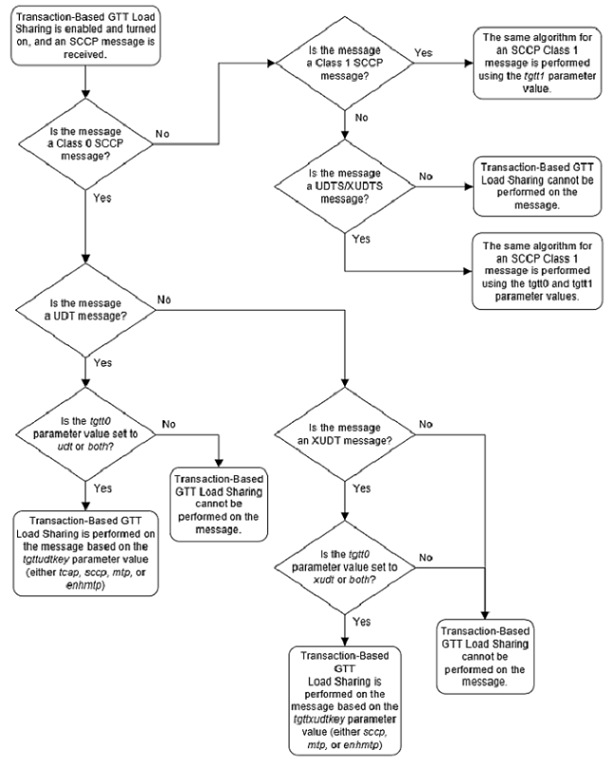
For more information on provisioning the Transaction-Based GTT Load Sharing option parameters, refer to the Changing the Transaction-Based GTT Load Sharing Options procedure.
Only load shared and combined dominant/load shared entity sets are used to determine the routing for messages that are processed by the Transaction-Based GTT Load Sharing feature.
Using a load shared entity set, the entire entity set is a part of one RC group and the messages are load-shared based on the Transaction Parameter in the entities in the entity set. If none of the entities in the entity set are available for routing, then the message is discarded and a UDTS/XUDTS message is generated if "Return on Error" is set in the SCCP message. A UIM is generated indicating that the message has been discarded.
Using a combined dominant/load shared entity set, the RC group containing the point code, or point code and SSN, obtained as a result of the global title translation process is used to determine how the message is routed. If none of the entities in this RC group are available for routing, the next higher cost RC group is chosen. This is repeated until an entity in an entity set is available for routing. When an entity is found that is available for routing, the message is routed according to the criteria in that entity. If none of the entities in the entity set are available for routing, the message is discarded. A UDTS/XUDTS message is generated if “Return on Error” is set in the SCCP message. A UIM is generated indicating that the message has been discarded.
Once the MSU key is generated, it is passed to to the Weighted GTT Load Sharing mode entity sets to determine how the message will be routed. If the Weighted GTT Load Sharing feature is active and weights have been assigned to the entity set, the Weighted GTT Load Sharing feature uses these weights to determine how to route the message. If no weights have been assigned to the entity set, then each RC group in the entity set is considered to be equally weighted.
Static routing is performed on all the messages that the Transaction-Based GTT Load Sharing feature has assigned an MSU key. Static routing always assigns an MSU key to the same node within an RC group. If static routing does not provide an available entity for routing the message, dynamic routing is used to find an available entity for routing the message. Figure 2-4 illustrates this process.
Figure 2-4 Message Routing using Transaction-Based GTT Load Sharing
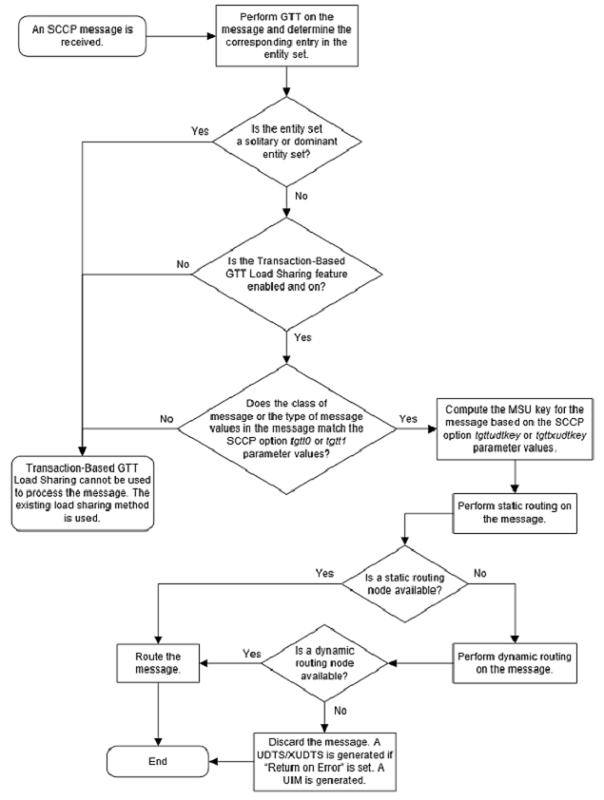
Provisioning the Transaction-Based GTT Load Sharing Feature
To provision the Transaction-Based GTT Load Sharing feature, perform these steps.
- Turn the GTT and EGTT features on using the
chg-featcommand. Add the required DSMs or SLIC cards to the database using theent-cardcommand. Perform Adding a Service Module. - Enable the Transaction-Based GTT Load Sharing feature
using the
enable-ctrl-featcommand. Perform the Activating the Transaction-Based GTT Load Sharing Feature procedure.Note:
The Transaction-Based GTT Load Sharing feature can be turned on in this step using thechg-ctrl-featcommand. If the Transaction-Based GTT Load Sharing feature is not turned on in this step, provisioning for the Transaction-Based GTT Load Sharing feature can still be performed. When the provisioning is completed, the Transaction-Based GTT Load Sharing feature can be turned on. The Transaction-Based GTT Load Sharing feature will not work until the feature is turned on either in this step or step 4. - Change the Transaction-Based GTT Load Sharing options,
if desired, using the
chg-sccpoptscommand. Perform the Changing the Transaction-Based GTT Load Sharing Options procedure. - Turn the Transaction-Based GTT Load Sharing feature on
using the
chg-ctrl-featcommand. Perform the Activating the Transaction-Based GTT Load Sharing Feature procedure.
SCCP Loop Detection
This feature detects SCCP looping of UDT/UDTS and XUDT/XUDTS messages. The SCCP Loop Detection feature requires a feature access key (FAK) for part number 893-0165-01 to enable the feature.
Normally, an STP sends GTT messages to the capability point codes (CPCs) of mated nodes for load sharing. However, approach can result in SCCP looping if the destination point code is the same as the originating point code or the point code of any intermediate in the network.
This looping can be resolved by eliminating the use of CPCs and verifying at an intermediate STP whether the OPC of the incoming MSU is the same as the true point code (TPC) of the DPC after GTT. However, CPCs are often used to implement LNP in addition to the SCCP.
The SCCP Loop Detection feature resolves the looping issue by providing a correlation between the MTP-designated TPCs/secondary point codes (SPCs) and the CPCs for all concerned STPs.
The SCCP Loop Detection feature is provisioned by configuring the Loopset Table and adding a loopset to a to a Global Title Translation.
The loopset commands define the correlation between MTP-designated point codes and the capability point codes of the STPs that detect SCCP looping. The GTT commands allow the administration, deletion, and retrieval of loopset table entries for a particular Global Title Translation.
The SCCP Loop Detection feature operates in Regular or Discard modes. In the Regular (default) mode, the SCCP Loop Detection Feature generates a UIM when it detects SCCP looping but does not discard the MSU. This UIM allows the operator to capture and verify MSUs throughout the system for SCCP looping. In the Discard mode, the SCCP Loop Detection feature generates a UIM when it detects SCCP looping and discards the MSU.
Provisioning the SCCP Loop Detection Feature
- Enable the SCCP Loop Detection feature using the
enable-ctrl-featcommand. Perform the Activating the SCCP Loop Detection Feature procedure.Note:
The SCCP Loop Detection feature can be turned on in this step using thechg-ctrl-featcommand. If the SCCP Loop Detection feature is not turned on in this step, provisioning for the SCCP Loop Detection feature can still be performed. When the provisioning is completed, the SCCP Loop Detection feature can be turned on. The SCCP Loop Detection feature will not work until the feature is turned on in this step. - Provision the loopset table using the
ent-loopsetcommand. Perform the Adding a Loopset procedure. - Add a loopset to the global title translation using
the
ent-gttorent-gtacommands. Perform Adding a Global Title Translation or Adding Global Title Address Information.
Flexible Linkset Optional Based Routing
Flexible Linkset Optional Based Routing allows the EAGLE to route GTT traffic based on the incoming link set and to route GTT traffic based on a variety of parameters (MTP, SCCP and TCAP depending on features that are enabled and turned on) in a flexible order on a per-translation basis.
Flexible Linkset Optional Based Routing can be used with or without the Origin-Based SCCP Routing or the TCAP Opcode Based Routing features. Flexible Linkset Optional Based Routing can be enabled and turned on only if the EGTT feature is turned on. If only the Flexible Linkset Optional Based Routing is enabled and turned on, the name of the incoming linkset that will help to determine how the GTT traffic is routed can be provisioned in the GTT selectors. If the Origin-Based SCCP Routing feature or the TCAP Opcode Based Routing feature is used with the Flexible Linkset Optional Based Routing feature, the name of the incoming linkset can be provisioned along with the provisioning for the Origin-Based SCCP Routing or the TCAP Opcode Based Routing features. Table 2-7 shows the type of GTT sets that can be provisioned for GTT selectors based on the features that are enabled and turned on.
Table 2-7 GTT Set Type and GTT Selector Combinations
| Feature Combinations | GTT Set Types for CdPA GTT Selectors | GTT Set Types for CgPA GTT Selectors |
|---|---|---|
| EGTT Only | CdPA GTA | Not Applicable |
| Origin-Based SCCP Based Routing Only | CdPA GTA | CgPA GTA, CgPA Point Code |
| Flexible Linkset Optional Based Routing Only | CdPA GTA, CdPA SSN, DPC | CdPA GTA, CdPA SSN, DPC |
| Flexible Linkset Optional Based Routing and TCAP Opcode Based Routing | CdPA GTA, Opcode, CdPA SSN, DPC | CdPA GTA, Opcode, CdPA SSN, DPC |
| Flexible Linkset Optional Based Routing and Origin-Based SCCP Based Routing | CdPA GTA, CgPA GTA, CgPA SSN, CgPA Point Code, OPC, CdPA SSN, DPC | CdPA GTA, CgPA GTA, CgPA SSN, CgPA Point Code, OPC, CdPA SSN, DPC |
| Flexible Linkset Optional Based Routing, Origin-Based SCCP Based Routing, and TCAP Opcode Based Routing | CdPA GTA, CgPA GTA, CgPA SSN, CgPA Point Code, OPC, Opcode, CdPA SSN, DPC | CdPA GTA, CgPA GTA, CgPA SSN, CgPA Point Code, OPC, Opcode, CdPA SSN, DPC |
Enhancements to Flexible Linkset Optional Based Routing
In previous releases, the GTT and TT command sets were replaced by the GTTSET, GTTSEL, and GTA command sets when the EGTT feature is turned on. Now the GTT and TT command sets can be used when EGTT feature is turned on.
In previous releases, the
selid parameter in the
ent-gttsel,
dlt-gttsel, and
chg-gttsel commands could be configured
only when the Flexible Linkset Optional Based Routing feature is enabled and
turned on or the Origin-Based SCCP Routing feature is enabled. Now the
selid parameter of these commands can be
configured when the EGTT feature is turned on.
An SCCP message (RT-on-GT or MTP-routed) received by the EAGLE can be routed (Relayed or Redirected) to another destination based on the routing data obtained from the EPAP database or PPSOPTS table by the EPAP-based service. This type of message is called a Service Relayed MSU. In previous releases, global title translation is not performed on Service Relayed MSUs. These messages are directly sent to destination obtained from EPAP database or PPSOPTS table.
Now global title translation can be performed Service
Relayed MSUs. To do this, these three optional parameters of the
ent-srvsel and
chg-srvsel commands are supported on per
Service Selector basis for the non-GTT Message Relay Services.
- GTT Required (
on=gttrqd,off=gttrqd) – This specifies whether or not global title translation is performed on Service Relayed MSUs. This parameter can be configured after the GTT feature is turned on. - GTT Selector ID (
gttselidfor theent-srvselcommand,ngttselidfor thechg-srvselcommand) – This is used as the SELID value for the GTT selector search when global title translation is performed on the Service Relayed MSU. This parameter can be configured only after EGTT feature is turned on. - Default Action (
dfltactfor theent-srvselcommand,ndfltactfor thechg-srvselcommand) – The action that is performed when the GTT selector search (using the GTT Selector ID from the Service Selector entry) fails for the Service Relayed MSU. This parameter can be configured only after EGTT feature is turned on or the GTT Action - DISCARD feature is enabled and turned on.
An example service selector entry is shown in Figure 2-5.
Figure 2-5 Message Relay Services and GTT Actions
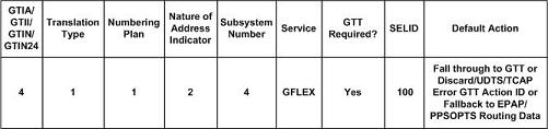
The GTT Required option indicates whether global title translation needs to be performed after successfully finding the routing data from the EPAP database or PPSOPTS database for non-GTT Message Relay Services. If the routing data is not found for non-GTT Relay Services from the EPAP database or PPSOPTS database, the standard Fall through to GTT procedure shall be performed.
Fallback to GTT
Fallback to GTT allows global title translation to be performed on Service Relayed MSUs by using the GTT Required parameter on per Service Selector basis for the non-GTT Message Relay Services shown in Table 2-8. Provisioning of the GTT Required parameter can be performed only if the EAGLE contains E5-SM4G cards.
Table 2-8 Services Supporting Fallback to GTT
| Service Name | Corresponding Feature which may relay MSU-based on EPAP or PPSOPTS Data |
|---|---|
| MNP/GPORT |
GPORT (Part Number: 893-0172-01) APORT (Part Number: 893-0166-01) IS41 GSM Migration (Part Number: 893-0173-01) |
| SMSMR | Prepaid SMS Intercept Ph1 (Part Number: 893-0067-01) |
| GFLEX |
G-Flex MAP Layer Routing (Part Number: 893-0217-01) G-Flex (Part Number: 893-0219-01) |
| INPMR |
ANSI-41 INP Query (Part Number: 893-0178-01) INP (Part Number: 893-0179-01) |
| IDPR |
IDP A-Party Routing (Part Number: 893-0333-01) IDP Service Key Routing (Part Number: 893-0336-01) |
| TTR | Currently no feature in this service performs message relay without encountering global title translation. The GTT Required parameter has no effect on this service. |
The GTT Required parameter is invoked only if a message is required to be relayed based on the routing data from EPAP database or PPSOPTS table after the successful execution of a non-GTT Message Relay Service. Table 2-8 lists the non-GTT Message Relay Services and the corresponding feature(s) which may result in the message being relayed based on the routing data from EPAP database or PPSOPTS table. If the GTT Required parameter value indicates that global title translation is required on the Service Relayed MSU, then global title translation is performed on the MSU modified by the relay service according to GTT hierarchy of the incoming link set. The default value of GTT Required parameter is set to indicate that global title translation is not required on the Service Relayed MSU. If global title translation is performed on the Service Relayed MSU successfully, then the message is processed through all the GTT-related features that are enabled and turned on.
Note:
Fallback to GTT applies only to the Service Relayed MSU. Query/Response and standard Fall Through to GTT procedures are do not apply to Fallback to GTT.Exceptions to Fallback to GTT
If a service performs global title translation on service specific parameters to obtain information required for message routing (for example, the MO SMS B-Party Routing feature in the SMSMR service finds the routing information by performing global title translation on the CDPN), then Fallback to GTT is not applied on those messages. The exceptions to Fallback to GTT are shown in Table 2-9.
Table 2-9 Exceptions to Fallback to GTT
| Service Name | Feature Name | Exception Description |
|---|---|---|
| MNP/GPORT |
IS41 GSM Migration (Part Number: 893-0173-01) |
The IGM SRI_SM Relay to Default IS41 SMSC functionality relays
the message to the default IS41 SMSC based on the global title translation of
the GTA defined by the
DEFIS41SMSC value shown in the
rtrv-gsmsmsopts output.
|
| All features under the MNP/GPORT service. | The MNP/GPORT service allows re-routing of messages when the service is offline. In this case, a global title translation parameter is already present that specifies whether global title translation is required when the service is offline. | |
| SMSMR |
MO SMS B-Party Routing (Part Number: 893-0246-01) |
MO SMS B-Party Routing performs global title translation on the TCAP B-Party digits (TCAP CDPN) and routes the message based on the global title translation results. |
| GFLEX | All features under the GFLEX service. | The GFLEX service allows re-routing of messages when the GFLEX service is offline. In this case, a global title translation parameter is already present that specifies whether global title translation is required when the service is offline. |
The service selector search is not performed for the MTP-routed messages whose CDPA GTI value is 0 (zero). The parameters required to perform Fallback to GTT are not available for MTP-routed messages whose CDPA GTI value is 0 (zero). Fallback to GTT on Service Relayed MSUs does not apply to messages whose CDPA GTI value is 0 (zero). If a message whose CDPA GTI value is 0 (zero) is relayed by an EPAP-based service, then global title translation is not be performed on the message.
GTT Selector ID and the Service Selector
For the non-GTT Message Relay Services, shown in
Table 2-8,
GTT selector IDs (SELIDs) can be provisioned. Only one GTT selector ID is
allowed for each service selector entry. The GTT selector ID is used to perform
GTT selector searches while performing global title translation on the Service
Relayed MSUs. The GTT selector ID is not used while performing global title
translation as a part of the existing Fall through to GTT message processing.
The GTT selector ID from service selector shall be used only in first GTT
selector search. If further GTT selector searches are required (when the
matching translation is provisioned with a CDSELID or CGSELID), then the GTT
selector ID found from the previous matched translation is used as is currently
done when processing the translation for the Origin-Based SCCP Routing and
Flexible Linkset Optional Based Routing features. The default value for the GTT
selector ID in the service selector entry is
none. The GTT selector ID in the service
selector can be provisioned when the EGTT feature is on. The Origin-Based SCCP
Routing and Flexible Linkset Optional Based Routing features are not required
to be enabled or turned on to provision the GTT selector ID in the service
selector.
Default Action and the Service Selector
For the non-GTT Message Relay Services shown in Table 2-8, a default action can be provisioned for each service selector entry. The default action parameter in the service selector can be one of these values.
- Fall through to GTT
- The Discard GTT Action ID
- The UDTS GTT Action ID
- The TCAP Error GTT Action ID
- Fallback (route the MSU based on the relay data)
The default action from the service selector is used only if the GTT selector search using the GTT selector ID from the service selector fails while performing global title translation on the Service Relayed MSU.
If the GTT selector search using the GTT selector ID from
the service selector fails and the default action in the service selector is
Fall through to GTT, then the action that is performed depends on the value of
the GTT selector ID in the service selector. If the GTT selector ID value in
the service selector is
none, then the message is discarded and
UIM 1042 is generated. If the GTT selector ID value in the service selector is
not
none, then the GTT selector search is
attempted again with GTT selector ID value of
none. If the subsequent GTT selector
search, attempted with GTT selector ID value of
none, also fails, then the message is
discarded and UIM 1042 is generated.
If the GTT selector search using the GTT selector ID from the service selector fails and the default action value in the service selector is either the Discard GTT Action ID, UDTS GTT Action ID, or the TCAP Error GTT Action ID, then the corresponding GTT action is performed.
If the GTT selector search using the GTT selector ID from the service selector fails and the default action value in the service selector is Fallback, then the message is relayed based on the routing data from the EPAP database or PPSOPTS table.
Overall Functionality
After successfully getting the routing data for non-GTT
Message Relay Services, if the GTT Required value is set to
Yes and the GTT SELID is provisioned for
this service, global title translation is performed on the MSU with specified
SELID value to find the matching translation based on the GTT hierarchy on the
linkset on which this MSU arrived.
- If a matching GTT selector is not found, the default action is applied to the MSU. The default action can be any of the actions shown in the Default Action and the Service Selector section. The default value of default action parameter is Fallback (route the MSU based on the relay data).
- If a global title translation is not found, then existing global title translation error handling procedures are applied.
- If a matching global title translation is found and:
- If the matched global title translation contains routing data, the global title translation routing data is used on top of the EPAP or PPSOPTS routing data.
- If the matched global title translation doesn't
contain routing data (
xlatparameter value isnone), the MSU continues to use the EPAP or PPSOPTS routing data. - If the matched global title translation contains
values for the
cggtmodorgtmodidparameters, then thecggtmodparameter value or the parameter values contained in the GT modification entry that is defined by thegtmodidparameter are applied to the MSU. - If a GTT action set is associated with the matched translation, then the GTT Actions feature is applied to the MSU.
- If matched translation contains a value for the
ccgtparameter, then theccgtparameter value is applied to the MSU as is currently done with the Advanced GT Modification feature.
Linkset Based Routing
After the Flexible Linkset Optional Based Routing feature enabled and turned on, Eagle considers the incoming link set as part of the GTT selection process for performing global title translation. If EAGLE receives MSUs with the same routing information on different link sets, it has the flexibility to route them based on different GTT rules. This also applies to the messages that fall through to GTT after being processed by MPS based services on the EAGLE. The incoming link set of the original MSU is used for these messages.
MSUs generated by the EAGLE that require global title translation are handled differently since they do not have a valid incoming link set. A separate set of GTT selector entries can be provisioned for these MSUs.
A separate set of GTT selector entries can be provisioned for messages generated by the EAGLE.
Flexible Linkset Optional Based Routing GTT Hierarchies
The Flexible Linkset Optional Based Routing feature introduced four more GTT hierarchies in addition to the GTT hierarchies used for the Origin-Based SCCP Routing feature. These hierarchies are shown in Table 2-10. These GTT hierarchies are available only when the corresponding feature is enabled, and turned on if necessary. All the GTT hierarchies are available when both the Origin-Based SCCP Routing and the Flexible Linkset Optional Based Routing features are enabled, and turned on if necessary. The GTT hierarchy can be provisioned on a link set basis or a system wide basis. The default GTT hierarchy is CdPA only.
Table 2-10 GTT Hierarchies
| EGTT Turned On Only | Origin-Based SCCP Routing Enabled Only | Flexible Linkset Optional Based Routing (FLOBR) Enabled and Turned On Only | Origin-Based SCCP Routing Enabled and Flexible Linkset Optional Based Routing Enabled and Turned On |
|---|---|---|---|
| CdPA only |
CdPA only Advanced CdPA, CdPA CgPA, Advanced CdPA, CdPA Advanced CdPA, CdPA, CgPA CgPA, CdPA CdPA, CgPA CgPA only |
CdPA only FLOBR CdPA only FLOBR CgPA only FLOBR CgPA, FLOBR CdPA FLOBR CdPA, FLOBR CgPA |
CdPA only Advanced CdPA, CdPA CgPA, Advanced CdPA, CdPA Advanced CdPA, CdPA, CgPA CgPA, CdPA CdPA, CgPA CgPA only FLOBR CdPA only FLOBR CgPA only FLOBR CgPA, FLOBR CdPA FLOBR CdPA, FLOBR CgPA |
- The same GTT set cannot be referred to more than once in the searching process.
- The number of database searches is limited to seven, including searches based on the calling party/called party SELID.
Note:
The DPC and CDSSN GTT set types can be searched only in a Flexible Linkset Optional Based Routing GTT hierarchy.Fallback Option
- Routing when the subsequent search failed in the Flexible Linkset Optional Based Routing feature.
- Routing when the same GTT set name is referred to more than once.
- Limiting the number of database searches to seven for the Flexible Linkset Optional Based Routing feature.
dfltfallback parameter of the
chg-sccpopts command and is used to
define the default value (“No”) for all translations by default. Each
translation may then be configured to use one of the fallback values. The
fallback option is configured with the
fallback parameter of the
ent-gta or
chg-gta commands. The
fallback parameter has these values.
sysdflt- use thedfltfallbackparameter value of thechg-sccpoptscommand for the translation.yes- global title translation is performed based on the last matched entry.no- global title translation fails and the MSU is discarded.
The per-translation option overrides the system default just for that translation. The Origin-Based SCCP Routing hierarchies do not use the fallback option.
Routing when the Subsequent GTT Set Search Failed
In this example, Set 1 is used to start the search. The matching translation in Set 1 points to Set 2. The matching translation in Set 2 points to Set 3 and there is no matching translation found in Set 3. Since the fallback option for the matched translation in Set 2 set to No, the MSU is discarded.
Figure 2-6 Action When the Subsequent Translation Search Fails
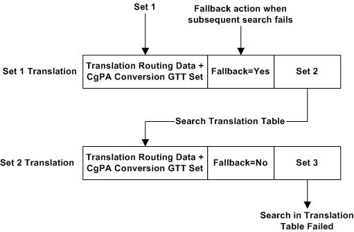
If the matching translation is not found in Set 2 (Set 2 Translation in Figure 2-6 is not found) and since the fallback option value in the Set 1 Translation is set to Yes, the MSU is routed based on the routing data in the Set 1 Translation. If the matching translation in Set 2 does not contain any GTT set/SELID combination (the Set 3 GTT set as shown in Figure 2-6 is not provisioned), then the fallback option is ignored and the MSU is routed based on routing data in the Set 2 Translation. If the matching translation in Set 1 is not found, then the GTT process fails.
Routing When the Subsequent Search for the SELID Fails
In this example, Set 1 is used to start the search. The matching translation in Set 1 (for example, a CdPA SSN/Opcode/CdPA GTA translation) contains SELID/Set 2 and also Set 3 (in this case Set 3 is an OPC GTT set).
Figure 2-7 Action When the Subsequent SELID Search Fails
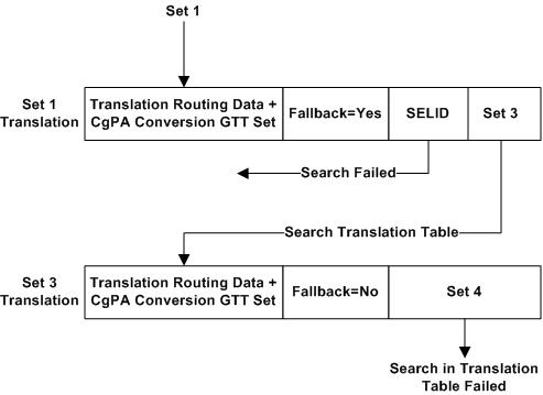
If a matching GTT selector is not found with an SELID in the Set 1 translation, the search continues searching for the matching translation in Set 3. If a matching translation is found in Set 3 and no matching translation is found in Set 4, the fallback option No in the Set 3 Translation is performed and the MSU is discarded. If a matching GTT selector is not found with an SELID in the Set 1 translation and a matching translation is not found in Set 3, the fallback option Yes in the Set 1 Translation is performed and the MSU is routed based on the routing data in the Set 1 Translation. If a GTT selector with an SELID results in a GTT set name that is already referred to, the action based on the fallback option in the Set 1 Translation is performed.
Routing When the Same GTT Set Name is Referred To More than Once
Figure 2-8 Action When the Same GTT Set Name is Referred to More Than Once
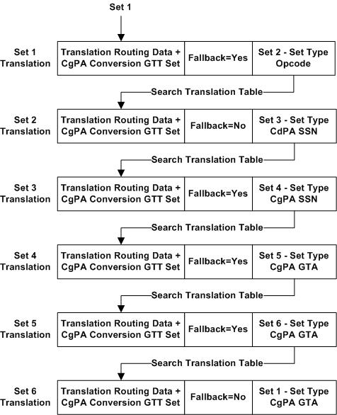
In
Figure 2-8,
even if the Set 5 Translation contains the Set 6 GTT set (Set 5 and Set 6 are
that same type of GTT sets), the Set 6 Translation will be searched for the
matching translation. If the Set 6 Translation contains the Set 1 GTT set and
since Set 1 has already searched, the Set 1 translation is not searched again
and the fallback option of the last matched translation is examined. Since the
last matched translation is found in Set 6 and the fallback option is set to
No, the MSU is discarded. UIM 1413 -
GTT(FLOBR) failure: duplicate set name
is generated to describe the condition. In
Figure 2-8,
if the Set 6 Translation was not found and since the fallback option in the Set
5 Translation is set to Yes, the MSU is routed based on the data in the Set 5
Translation.
Limiting the Number of Database Searches for the Flexible Linkset Optional Based Routing Feature
The number of database searches is limited to seven when the Flexible Linkset Optional Based Routing feature is enabled and turned on. This includes searching the GTT selector table when a translation contains the CgPA SELID or CdPA SELID parameter.
Figure 2-9 Limit the Number of Database Searches
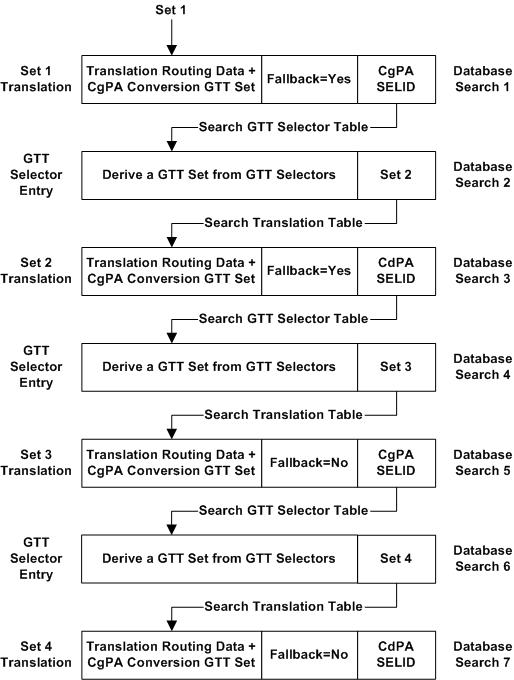
As shown in
Figure 2-9,
when a translation contains the CdPA SELID or CgPA SELID, the search in the GTT
selector table is also counted toward the maximum seven searches. After
completing seven searches, if the search is terminated because of the maximum
seven search criteria, the action defined in the last matched Set 4 Translation
fallback option (in this case No) is performed and MSU is discarded. UIM 1412 -
GTT (FLOBR) failure: max search depth is
generated to describe the condition. After completing seven searches, if the
last matched translation contains no GTT set/SELID data (if the CdPA SELID data
is not provisioned in the Set 4 Translation), the MSU is routed based on the
routing data in the Set 4 Translation. The first GTT selector search when the
GTT functionality is selected (deriving Set 1 in
Figure 2-9)
is not counted toward the maximum seven search criteria.
Limiting the Number of GTT Set Searches for the Flexible Linkset Optional Based Routing Feature
The number of GTT set searches is limited to seven when the Flexible Linkset Optional Based Routing feature is enabled and turned on.
Figure 2-10 Limit the Number of GTT Set Searches
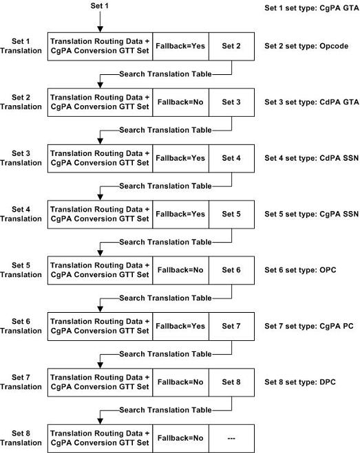
As shown in
Figure 2-10,
after completing seven GTT set searches, if the search is terminated because of
the maximum of seven searches have been performed, the action defined by the
fallback option in Set 7 Translation, in this case No, is performed and the MSU
is discarded. UIM 1412 -
GTT(FLOBR) failure: max search depth is
generated to describe the condition. If the Set 7 Translation contains no GTT
sets, Set 8 is this case, the MSU is routed based on the routing data in the
Set 7 Translation.
GTT for MSUs Generated by the EAGLE
The EAGLE performs global title translation on some
messages generated by itself. These messages are sent in response to queries
received by local subsystems. SCCP UDTS and XUDTS messages also fall under this
category. Global title translation is performed to find the destination for the
responses when the SCCP calling party address in query messages is Route-on-GT.
Since there is no valid incoming link set for messages generated by the EAGLE,
a special set of GTT selector entries are used when the Flexible Linkset
Optional Based Routing feature is enabled and turned on. The
eaglegen=yes parameter in the
ent-/dlt-/chg-/rtrv-gttsel commands is used to provision a GTT
selector for messages generated by the EAGLE. If the
eaglegen=no parameter is specified for a
GTT selector, the GTT selector is not provisioned for messages generated by the
EAGLE.
eaglegen=yes parameter is specified for
a GTT selector,
- Any CgPA related parameters, the linkset name, and SELID parameters cannot be specified.
- The Flexible Linkset Optional Based Routing feature must be enabled and turned on.
- A GTT set with the CdPA GTA set type must be specified.
- A dummy link set name
Eagle-Genis displayed in thertrv-gttselcommand output.
If the GTT set name assigned to a GTT selector for
messages generated by the EAGLE is changed with the
chg-gttsel command, the new GTT set must
be a CdPA GTT set.
If no match is found in the GTT selector entries that
contain the
eaglegen=yes parameter, the entries with
LSN value
ANY are searched. If a matching entry is
still not found, for GTI=4 entries, the GTT set with CdPA set type for NP and
NAI values Default are returned. For GTI=2 entries, a match not found message
is returned. The Flexible Linkset Optional Based Routing feature hierarchies do
not apply for GTT selectors provisioned for messages generated by the EAGLE and
the CDPA Only GTT mode is used for such translations.
GTT Selector Key
Table 2-11 defines the keys into GTT selector table based on the feature combination. If a feature supports specific parameters and that feature is not enabled or turned, if necessary, then default values for these parameters are entered into the database.
Table 2-11 GTT Selector Key
| Feature Combination | Selector Type | GTI, Domain, TT, (NP and NAI if the GTII/GTIN/GTIN24=4) | CgPA SSN | SELID | Linkset Name |
|---|---|---|---|---|---|
| EGTT | CdPA Only | X | - |
X (See Note 1) |
- |
| Origin-Based SCCP Routing | CdPA | X | - |
X (See Note 1) |
- |
| CgPA | X | X | X | - | |
| Flexible Linkset Optional Based Routing | CdPA | X | - | X | X |
| CgPA | X | - | X | X | |
| Origin-Based SCCP Routing and Flexible Linkset Optional Based Routing | CdPA | X | - | X | X |
| CgPA | X | X | X | X | |
| Messages generated by the EAGLE | CdPA only | X | - | - |
X (See Note 2) |
|
Note:
|
|||||
Searching Order in the GTT Selector Table with the Flexible Linkset Optional Based Routing Feature
Table 2-12 CdPA GTT Selector Keys
| Priority | GTI, Domain, TT, (NP and NAI if the GTII/GTIN/GTIN24=4) | Linkset Name | SELID | CdPA GTT Selector Found or Not Found |
|---|---|---|---|---|
| 1 | Exact | Exact | Exact | If a CdPA GTT set is provisioned for the GTT selector keys, the GTT selector is considered found. Otherwise, the GTT selector is not found. See the Note. |
| 2 | Exact | Any | Exact | |
| Note: If an Origin-Based SCCP Routing GTT hierarchy is being used, the CdPA GTT set must be a CDGTA GTT set and the CgPA GTT set must be either a CGGTA or CGPC GTT set. If a Flexible Linkset Optional Based Routing feature GTT hierarchy is being used, any GTT set type can be used. | ||||
Table 2-13 CgPA GTT Selector Keys
| Priority | GTI, Domain, TT, (NP and NAI if the GTII/GTIN/GTIN24=4) | Linkset Name | SELID | CgPA SSN | CgPA GTT Selector Found or Not Found |
|---|---|---|---|---|---|
| 1 | Exact | Exact | Exact | Exact | If a CgPA GTT set is provisioned for the GTT selector keys, the GTT selector is considered found. Otherwise, the GTT selector is not found. See the Note. |
| 2 | Exact | Exact | Exact | Any | |
| 3 | Exact | Any | Exact | Exact | |
| 4 | Exact | Any | Exact | Any | |
| Note: If an Origin-Based SCCP Routing GTT hierarchy is being used, the CdPA GTT set must be a CDGTA GTT set and the CgPA GTT set must be either a CGGTA or CGPC GTT set. If a Flexible Linkset Optional Based Routing feature GTT hierarchy is being used, any GTT set type can be used. | |||||
Table 2-14 Messages Generated by the EAGLE GTT Selector Keys
| Priority | GTI, Domain, TT, (NP and NAI if the GTII/GTIN/GTIN24=4) | Linkset Name | Messages Generated by the EAGLE GTT Selector Found or Not Found |
|---|---|---|---|
| 1 | Exact | Eagle=Gen | If a CdPA GTT set with the CDGTA GTT set type is provisioned for the GTT selector keys, the GTT selector is considered found. Otherwise, the GTT selector is not found. See the Note. |
| 2 | Exact | Any | |
| 3 | For GTI=4, the GTT set with the values Default for the NP and NAI parameters. | Any | |
| Note: If an Origin-Based SCCP Routing GTT hierarchy is being used, the CdPA GTT set must be a CDGTA GTT set and the CgPA GTT set must be either a CGGTA or CGPC GTT set. If a Flexible Linkset Optional Based Routing feature GTT hierarchy is being used, any GTT set type can be used. | |||
Hardware Requirements
To enable the Flexible Linkset Optional Based Routing feature DSM or SLIC cards must be provisioned in the database. Any Legacy Cards must be replaced.
Provisioning the Flexible Linkset Optional Based Routing Feature
To provision the Flexible Linkset Optional Based Routing feature, perform these steps.
- Turn the GTT and EGTT features on using the
chg-featcommand. Add the required DSM or SLIC cards to the database using theent-cardcommand. Perform Adding a Service Module. - Enable and turn on the Flexible Linkset Optional Based
Routing feature using the
enable-ctrl-featand thechg-ctrl-featcommands. Perform Activating the Flexible Linkset Optional Based Routing Feature. - Provision the required GTT sets using the
ent-gttsetcommand. Perform Adding a GTT Set. - Provision the required GTT translations using the
ent-gtacommand. Perform Adding Global Title Address Information. - Provision the required GTT selectors using the
ent-gttselcommand. Perform Adding a GTT Selector. - Change the default fallback option, if desired, using
the
chg-sccpoptscommand. Perform Changing the Default GTT Mode Options.
TCAP Opcode Based Routing
TCAP Opcode Based Routing allows the EAGLE to route messages based on their operation codes. When the TCAP Opcode Based Routing feature is enabled and turned on, this information contained in the TCAP portion of messages is used for performing global title translation. TOBR is also able to process Segmented XUDT(S) message.
- To perform global title translation on ITU messages:
- Message Type / Package Type
- Application Context Name
- Operation Code
- To perform global title translation on ANSI messages:
- Package Type
- Operation Code Family
- Operation Code Specifier
TCAP Opcode Based Routing requires that the Flexible Linkset Optional Based Routing feature is enabled and turned on. TCAP Opcode Based Routing can be used with or without the Origin-Based SCCP Routing feature. Table 2-7 shows the type of GTT sets that can be provisioned for GTT selectors based on the features that are enabled and turned on.
TCAP Decoding
As part of the TCAP Opcode Based Routing feature, the EAGLE attempts to decode TCAP portion of all UDT/UDTS/XUDT/XUDTS queries coming to service modules for global title translation. Messages are decoded only if a TOBR Opcode Quantity is enabled. The objective of this decoder is not to validate the correctness of the message but simply to obtain the required TCAP data. The message is validated only for the encoding rules that are required to successfully decode the required TCAP information. In general, Tag-Length-Value encoding is validated; unsupported Tag values are skipped if they are encountered, unless a specific Tag order is expected. If the decoding fails, global title translation is still performed on the message using some default values for the TCAP data that denote their absence in the message. The TCAP Opcode Based Routing feature supports the following messages.
- ITU TCAP Message/Package Types:
- Begin
- Continue
- End
- Abort
- Unidirectional
- ANSI TCAP Message/Package Types:
- Unidirectional
- Query With Permission
- Query Without Permission
- Response
- Conversation With Permission
- Conversation Without Permission
- Abort
Other message/package types are treated as an unknown message type and are not proceed with the decoding. This is not considered an error, because many non-TCAP SCCP messages are processed by the EAGLE. For these messages, the TCAP data is not used for routing. If an opcode translation set is encountered while performing global title translation, the opcode translation set is considered as a “translation not found” in that set. Such messages are routed based on last matched translation depending on its fallback option. Refer to Flexible Linkset Optional Based Routing for more details on the fallback option.
The application context name (ACN) is used for all supported ITU TCAP messages except Abort messages. No attempt to retrieve the ACN is made for Abort messages. All other supported messages may have a Dialog portion containing Dialogue Request / Unidirectional Dialogue / Dialogue Response PDU, from which the ACN is retrieved. If no Dialog portion is detected, then the ACN is assumed to be NONE. The TCAP Opcode Based Routing feature attempts to find the operation code (opcode) in all supported ITU TCAP messages except Abort. These messages must contain Invoke or Return Result (Last or Not Last) as the first component. If not, the opcode is assumed to be NONE.
- The SCCP data portion for UDT(S)/XUDT(S) messages is a 1-byte length field. It has a maximum value of 255 bytes.
- All TCAP lengths of 255 bytes or less can be encoded with a 2-byte length field.
At any point of time during the decoding process, if it is found that the current position in TCAP message is extending beyond the SCCP data portion length, the decoder process stops.
TCAP Opcode Based Routing GTT Sets
The TCAP Opcode Based Routing feature introduces the GTT
Set Opcode with set type
opcode. The opcode GTT set supports
translations for ANSI and ITU opcodes.
TOBR Opcode Quantities
enable-ctrl-feat command. These are the
quantities that can be enabled:
- 3 opcode translations (part number : 893027901)
- 6 opcode translations (part number : 893027902)
- 12 opcode translations (part number : 893027903
- 24 opcode translations (part number : 893027904)
- 48 opcode translations (part number : 893027905)
- 96 opcode translations (part number : 893027906)
- 1 million opcode translations (part number : 893027907) - the GTT translation table capacity is controlled by the XGTT Table Expansion feature.
MAP Based Routing
- IMEI
- IMSI
- MSISDN
- VLRNb
- SMRPOA
- SMRPDA
These GTT settypes allow additional MAP Components to be used in the selection process. These GTT settypes are allowed to be provisioned ONLY in GTA entries from an OPCODE GTT Set type or one of the other GTT settypes supported by SS7 Firewall feature.
Additional opcodes supported by MAP Based Routing include:
- PurgeMS
- RestoreData
- Reset
- RegisterSS
- USSD-Request
- USSD-Notify
- SnedAuthenticationInfo
- CheckIMEI
- Provide Subscriber Location
- SubscriberLocationReport
- UpdateGPRSLocation
When an MSU is processed by the TOBR GTT translation with the OPTSN as one of MAP Based Routing settypes, the EAGLE decodes the TCAP part and extracts the required TCAP parameter from the MSU. The digits in this parameter are used as the key to search for the translation in the GTT set.
Only TCAP Package Types BEGIN, CONTINUE & END are supported for MAP Based Routing. OPTSN with one of the MAP Based Routing GTT settypes are allowed to be provisioned only for TOBR GTA entries that have PKGTYPE as BGN, or CNT or END.
- If the component parameter is not present in the MSU,
the user will be able to provision an alternate GTT Set which looks at another
TCAP parameter. In the
ent/chg-gttsetcommands, a new parameter NPSN (Not Present Set Name) is used to allow provisioning of this alternate GTT Set.Note:
The alternate GTT Set will only be used if the MAP parameter is optional and not present in the MSU. If the MAP parameter is mandatory for that opcode or was present but the lookup failed, the NPSN GTT Set will not be used. - The NPSN depth search is not part of the FLOBR depth search
For some MAP operations, it is possible for IMSI/MSISDN to be present in the Destination Reference of the dialogue portion; however, currently this feature only supports decoding the key from only the component portion of the TCAP part. If the required parameter is not present in the component portion, the parameter will be deemed 'not present' even though it is in the dialogue portion.
- If the Dialogue Portion is present in the message, pick the last byte of the ACN. MAP Based Routing is only decoding the last byte of the ACN to determine the MAP version, not validating whether the MAP operation is supported with the ACN in the message.
- If the Dialogue Portion is not present, the MAP version provisioned with the Opcode translation will be used as the MAP version.
If the Dialogue Portion is present but the ACN could not be decoded, then the default version will be picked up from the defmapvr parameter for further processing. defmapvr is configured in opcode translation and used for opcodes that have MAP translations associated with it.
Figure 2-11 MAP Based Routing Flowchart
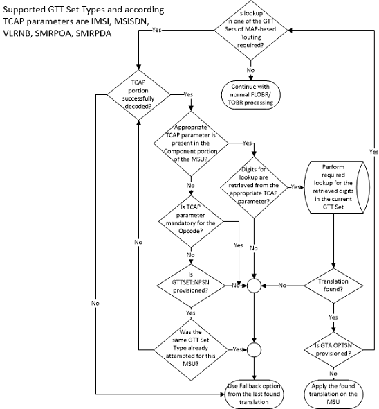
GTT Translations
- Advanced GT Modification
- Variable Length Global Title Translation
- SCCP Loop Detection
- Intermediate GTT Load Sharing
- ANSI/ITU SCCP Conversion
- Flexible GTT Load Sharing
TCAP Opcode Based Routing Feature Translations with an ANSI Opcode
The key for ANSI opcode translations is the ANSI opcode specifier, the ANSI TCAP Package Type, and the Family (part of ANSI TCAP opcode field). The ANSI opcode specifier values can be 0 to 255, None, and * (any opcode specifier value). The value none indicates the absence of the opcode in the incoming MSU. The ANSI TCAP Package Type values are Unidirectional, Query with Permission, Query without Permission, Response, Conversation with Permission, Conversation without Permission, Abort, and Any. The Family value can be 0 to 255, None, and * (any family value). While provisioning, when ANSI TCAP Package type is specified as Abort, then the ANSI opcode specifier and Family values must be none. Since the opcode specifier and family values exist together in the incoming MSU, both values in the translation must be none if either value is specified as none.
Search Order for the TCAP Opcode Based Routing Feature Translations with an ANSI Opcode
Table 2-15 shows the searching order for The TCAP Opcode Based Routing feature translations with an ANSI opcode. The ANSI opcode translations are matched to ANSI MSUs:
Table 2-15 Search Order for the TCAP Opcode Based Routing Feature Translations with an ANSI Opcode
| Priority | TCAP Package Type | ANSI Opcode | Family |
|---|---|---|---|
| 1 | Exact (package type value) | Exact (the value none or a number) | Exact (the value none or a number) |
| 2 | Exact | Exact | Any |
| 3 | Exact | Any | Exact |
| 4 | Exact | Any | Any |
| 5 | Any | Exact | Exact |
| 6 | Any | Exact | Any |
| 7 | Any | Any | Exact |
| 8 | Any | Any | Any |
TCAP Opcode Based Routing Feature Translations with an ITU Opcode
The key for ITU opcode translations is the ITU opcode, the ITU TCAP Package Type, and the application context name (ACN). The ITU opcode values can be 0 to 255, None, and * (any opcode value). The value none indicates the absence of the opcode in the incoming MSU. The ITU TCAP Package Type values are Begin, End, Continue, Abort, Unidirectional, and Any. The ACN value can be 1 to 7 bytes - the value of each byte is from 0 to 255, none and Any. The none value indicates the absence of the ACN value in the incoming MSU. Though the VGTT feature is not supported for opcode GTT set, different digit length ACNs for the opcode GTT set can be provisioned. While provisioning, when ITU TCAP Package type is specified as Abort, then the ITU opcode and ACN values must be none. An ACN value cannot contain a mixture numbers, the value none, or the value Any. Table 2-16 shows the valid and invalid values for the ACN.
Table 2-16 Valid and Invalid ACN Values
| ACN Value | Does The TCAP Opcode Based Routing Feature Support this ACN? | Information |
|---|---|---|
| Bytes 1-2-3-4-5 | Yes | The remaining bytes are treated as None. |
| Bytes 1-2-3-4-5-6-7 | Yes | |
| Byte 1 | Yes | The remaining bytes are treated as None. |
| None | Yes | All the bytes are treated as None. |
| Any | Yes | All the bytes are treated as Any. |
| Byte 1-none-Byte 2 | No | |
| Byte 1-any-Byte 3-Byte4 | No | |
| Any-Byte1 | No | |
| None-Any-Byte1 | No |
Search Order for the TCAP Opcode Based Routing Feature Translations with an ITU Opcode
Table 2-17 shows the search order for the TCAP Opcode Based Routing feature translations with an ITU opcode when the TCAP Opcode Based Routing feature is enabled and turned on. The ITU opcode translations are only matched to ITU MSUs. If any MSU contains a 7-byte ACN value, an attempt is made to match the 7-byte ACN values with the values in the database. If a match is not found, no attempt is made to match any 6-/5-/4-/3-/2-/1-byte ACN values in the database. An attempt is made to match to any ACN=ANY entries in the database, if these entries are provisioned in the database.
Table 2-17 Search Order for the TCAP Opcode Based Routing Feature Translations with an ITU Opcode
| Priority | TCAP Package Type | ANSI Opcode | ACN |
|---|---|---|---|
| 1 | Exact (package type value) | Exact (the value none or a number) | Exact (the value none or a number) |
| 2 | Exact | Exact | Any |
| 3 | Exact | Any | Exact |
| 4 | Exact | Any | Any |
| 5 | Any | Exact | Exact |
| 6 | Any | Exact | Any |
| 7 | Any | Any | Exact |
| 8 | Any | Any | Any |
TCAP Segmentation SMS Support Phase 2
An objective of the TCAP Opcode Based Routing feature is to allow EAGLE to route segmented TCAP SMS messages in the same manner as non-segmented TCAP messages are routed. This would mean routing all TCAP SMS messages within a particular transaction to the same place. Routing rules based on the opcode are used to route messages for special application handling. These rules work well for non-segmented TCAP messages. However they do not work well for segmented TCAP messages, because the initial BEGIN message does not contain an opcode. These messages must be identified for special routing based on other criteria. The TCAP Opcode Based Routing feature achieves this discrimination by allowing the EAGLE to route messages based on the TCAP Opcode and Dialogue portion information in the message. The EAGLE uses the Application Context Name from the Dialogue portion to route the TCAP Begin messages without the component portion (and without the operation code). The same routing rules to route messages with an ACN and opcode, an ACN only, or an opcode only value can be used. GSM SMS messages work particularly well in this solution, because there is a 1 to 1 correspondence between the ACN and opcode values.
Hardware Requirements
To enable the TCAP Opcode Based Routing feature E5-SM4G cards must be provisioned in the database. Any SMs must be replaced by the E5-SM4G cards.
Provisioning the TCAP Opcode Based Routing Feature
To provision the TCAP Opcode Based Routing feature, perform these steps.
- Turn the GTT and EGTT features on using the
chg-featcommand. Add the required E5-SM4G cards to the database using theent-cardcommand. Perform the Adding a Service Module procedure. - Enable and turn on the TCAP Opcode Based Routing
feature using the
enable-ctrl-featand thechg-ctrl-featcommands. Perform the Activating the TCAP Opcode Based Routing Feature procedure. To enable and turn on the TCAP Opcode Based Routing feature, the Flexible Linkset Optional Based Routing feature must be enabled and turned on. The status of the Flexible Linkset Optional Based Routing feature is verified when the Activating the TCAP Opcode Based Routing Feature procedure is performed. - Enable a TOBR Opcode Quantity using the
enable-ctrl-featcommand. Perform the Enabling a TOBR Opcode Quantity procedure. - Provision the required GTT sets using the
ent-gttsetcommand. Perform the Adding a GTT Set procedure. - Provision the required GTT translations using the
ent-gtacommand. Perform the Adding Global Title Address Information procedure. - Provision the required GTT selectors using the
ent-gttselcommand. Perform the Adding a GTT Selector procedure.
GTT Actions
The GTT Actions allows these actions to be applied to MSUs during global title translation message processing:
- Discard
- UDTS
- Duplicate
- TCAP error
- Forward
- Services
- SFLOG
- SFTHROT
- SCPVAL
- SFAPP
Note:
GTT Actions SFTHROT and SFLOG are not supported on GTT-enabled IPSG cards in Release 46.5.A GTT action entry contains one GTT action, a GTT action
ID, data specific to the action, and a reference count. These actions are
contained in a GTT action entry. The EAGLE contain a maximum of 2000 GTT action
entries. A GTT action entry, identified by the GTT action ID, is assigned to a
GTT action set. The GTT action set is assigned to the global title address
entry. The reference count in the GTT action entry shows the number of database
entities GTT action sets that reference the GTT action entry. When a GTT action
entry is referenced by a GTT action set, a service selector ID, or a Forward
GTT action entry, or an LNP service, the reference count is increased by 1.
When a GTT action set, a service selector ID, or a Forward GTT action entry, or
an LNP service no longer references the GTT action entry, the reference count
is decreased by 1. The GTT action entry can be removed only when the reference
count is zero. The data for each GTT action entry is shown in the
rtrv-gttact
output.
Discard GTT Action
ent-gttact command using these
parameters.
actid- the GTT action IDact=disc- the discard GTT actionon=uimreqd- UIM 1193GTT Action DISCARD DISCARDED MSUis generated when the MSU is discarded.off=uimreqd- UIM 1193GTT Action DISCARD DISCARDED MSUis not generated when the MSU is discarded.Note:
If neither theon=uimreqdoroff=uimreqdparameters are specified, theUIMREQDvalue defaults tooff.
An example of the Discard GTT action entry is shown in Figure 2-12.
Figure 2-12 Discard GTT Action Entry
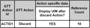
UDTS GTT Action
ent-gttact command using these
parameters.
actid- the GTT action IDact=udts- the UDTS GTT actionudtserr= 0 to 255on=uimreqd- UIM 1192GTT Action UDTS DISCARDED MSUis generated when the MSU is discarded.off=uimreqd- UIM 1192GTT Action UDTS DISCARDED MSUis not generated when the MSU is discarded.Note:
If neither theon=uimreqdoroff=uimreqdparameters are specified, theUIMREQDvalue defaults tooff.
An example of the UDTS GTT action entry is shown in Figure 2-13.
Figure 2-13 UDTS GTT Action Entry
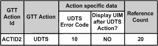
TCAP Error GTT Action
ent-gttact command using these
parameters.
actid- the GTT action IDact=tcaperr- the TCAP Error GTT actionatcaperr= 0 to 255 - the ANSI TCAP error codeitcaperr= 0 to 255 - the ITU TCAP error codeon=uimreqd- UIM 1077GTT Action TCAP ERROR DISCARDED MSUis generated when the MSU is discarded.off=uimreqd- UIM 1077GTT Action TCAP ERROR DISCARDED MSUis not generated when the MSU is discarded.Note:
If neither theon=uimreqdoroff=uimreqdparameters are specified, theUIMREQDvalue defaults tooff.
An example of the TCAP Error GTT action entry is shown in Figure 2-14.
Figure 2-14 TCAP Error GTT Action Entry
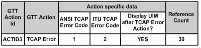
Duplicate GTT Action
GTT Action DUPLICATE FAILED is
generated. A Duplicate GTT action entry is provisioned with the
ent-gttact command using these
parameters.
actid- the GTT action IDact=dup- the Duplicate GTT actionpc/pca/pci/pcn/pcn24=the point code of the duplicate noderi=<gt, ssn>- the routing indicator in the SCCP called party address of the duplicated copy of MSU.mrnset=<1 - 3000 or none>- the MRN set ID, shown in thertrv-mrnoutput, or no MRN set IDmapset=<1 - 36000 or dflt>- The MAP set ID or the default MAP set ID, shown in thertrv-mapoutputssn=<2 - 255>- The subsystem number in the SCCP called party address of the duplicated copy of MSU.loopset- the name of the loopset, shown in thertrv-loopsetoutput, associated with the Duplicate GTT action entrycggtmodid- the calling party global title modification identifier, shown in thertrv-gtmodoutput, associated with the calling party of a GTT action entry.cdgtmodid- the called party global title modification identifier, shown in thertrv-gtmodoutput, associated with the called party of a GTT action entry.cgpc/cgpca/cgpci/cgpcn/cgpcn24- the calling party point code in the outgoing message when thecgpcogmsgparameter value isprovcgpc. The network type of thecgpc/cgpca/cgpci/cgpcn/cgpcn24value must be the same as thepc/pca/pci/pcn/pcn24value.cgpcogmsg=<dflt, cgpcicmsg, opcicmsg, provcgpc>- the data that is used as the calling party point code in the outgoing message.dflt- default. The standard Global Title Translation process supplies the calling party address point code.Note:
If thecgpc/cgpca/cgpci/cgpcn/cgpcn24and thecgpcogmsgparameters are not specified, the default value for thecgpcogmsgparameter isdflt.cgpcicmsg- the calling party address point code data from the incoming MSUopcicmsg- the OPC data from the incoming MSUprovcgpc- thecgpc/cgpca/cgpci/cgpcn/cgpcn24value provisioned in the Duplicate GTT Action.
on=useicmsg- The incoming MSU is duplicated to the MSU. The incoming MSU is the MSU before applying the translation data by any EPAP service or global title translation process and before applying the GTT actions data. However, it is possible that some data in the MSU may have been modified by the LIM before arriving on the service module. The TCAP layer may have been modified by any EPAP service.off=useicmsg- The translated MSU is duplicated to the MSU. The translated MSU is the MSU after applying the translation data by any EPAP/ELAP service or global title translation process and before applying the GTT actions data. However, it is possible that some data in the MSU may have been modified by the LIM before arriving on the service module. The TCAP layer may have been modified by any EPAP service.Note:
If neither theon=useicmsgoroff=useicmsgparameters are specified, theUSEICMSGvalue defaults tooff.
An example of the Duplicate GTT action entry is shown in Figure 2-15.
Figure 2-15 Duplicate GTT Action Entry
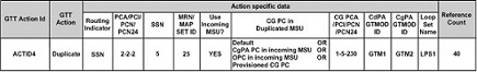
cgpcogmsg parameter value in the
Duplicate GTT action entry,
- The CgPA point code field in the duplicated MSU is updated.
- If the CgPA point code field is not present in the
duplicated MSU, the OPC field is updated with the
cgpcogmsgparameter value in the Duplicate GTT action entry. - If a value other than
dfltforcgpcogmsgparameter value in the Duplicate GTT action entry and the CgPA point code or the OPC is not present or cannot be used in the MSU, The EAGLE uses thedfltvalue of thecgpcogmsgparameter; the CgPA point code supplied by standard global title translation process is applied.
Forward GTT Action
The Forward GTT action diverts the translated MSU to
another node. If the EAGLE fails to forward the MSU, UIM 1079
GTT Action FORWARD FAILED is generated.
An example of the Forwarded GTT action entry is shown in Figure 2-16.
Figure 2-16 Forward GTT Action Entry
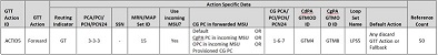
defactid) parameter. The
defactid parameter indicates what action
is taken when the EAGLE fails to route the forwarded MSU. These are the default
actions are:
- Discard GTT action entry ID - perform the action defined by the Discard GTT entry ID.
- UDTS GTT Action ID - perform the action defined by the UDTS GTT action entry ID.
- TCAP Error GTT Action ID - perform the action defined by the TCAP Error GTT action entry ID.
- Fallback to the translated MSU (
fallback). The translated MSU is routed according to the routing data in the translated MSU. The routing data can be from an EPAP service or the PPSOPTS table, or the global title translation process. Fallback to the translated MSU is the default value for thedefactidparameter if thedefactidparameter is not specified.
Services GTT Action
GTT Action Services allow triggering a Service as a GTT action either based on the usual GTT rules or after FLOBR/TOBR execution.
An example of the Services GTT action entry is shown in Figure 2-17.
Figure 2-17 Services GTT Action Entry
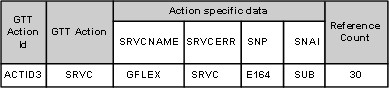
Any of these three Services can be applied on the translated MSU -GPORT, GFLEX or SMSMR. The new GTT Actions Service cannot be applied on MTP routed MSUs.
GTT Action Services can work with the RTDB Split Feature (240M DN and 240M IMSIs via split database). This compatibility is possible only when GTT Action is executed on GTT enabled LIM cards.
- GTT Action ID
- GTT Action - SRVC
- SRVCNAME - Service name applied on the translated MSU
- SNP - Service Numbering Plan of the service applied
- SNAI - Service nature of the address indicator of the service applied
- SRVCERR - GTT/SRV
If the Service is triggered by the GTT Action Service fails, the MSU can be processed by applying the results of the pre-Service GTT or processing with the specific Service error.
SFTHROT GTT Action
The SFTHROT GTT Action is used to control the throttling of MSUs on SCCP cards. Thirty-two (32) GTT actions of the type SFTHROT will be allowed. For each such GTT action, the user will provision a threshold as a maximum number of MSUs hitting the GTT action in a 30-second period.
When an MSU hits a GTT action of the type SFTHROT, the SCCP card updates the count of messages that hit the Throttling GTT action and periodically communicates the count to the OAM card via maintenance blocks. The OAM sums the total number of these messages on all SCCP cards, decides if the number of messages has crossed the provisioned threshold, and then communicates to the SCCP card to start throttling the messages.
The OAM will communicate to the SCCP card that the threshold for a particular Throttling GTT action has crossed. The SCCP card will then put that GTT action in the BLOCKED state for the remaining time of the current 30-second window. While the Throttling GTT Action is in the BLOCKED state, any MSU hitting that GTT action will be discarded.
- BURSTS - parameter used to signify the number of previous 30 second windows from where the unused capacity can be carried over to the current window.
- THRESHOLD - If the count of MSUs hitting SFTHROT action exceeds this value, the MSU will be discarded.
- DEFACTID - Default
Action ID. The default action that is performed when the
sfthrotGTT Action fails.
A GTT Action set will only have a maximum of one SFTHROT GTT Action.
Figure 2-18 Throttling Framework
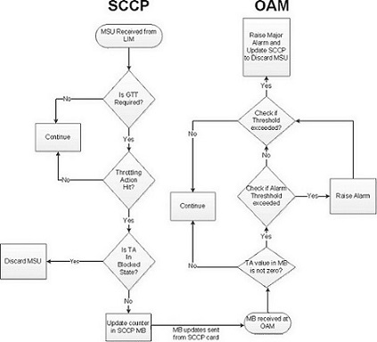
SFLOG GTT Action
The SFLOG GTT Action is used for logging. An SCCP card will be allowed to log up to 100 log event/second. The SCCP card will transfer all the log events for the MSUs that will hit the SFLOG GTT action. Two IPS cards will act as the Primary and Secondary Logging Card. At any given time, the Primary logging card will be actively logging. The standby logging card will only be used for logging if the active logging card is unavailable for logging for an extended period of time.
Table 2-18 Roles and Responsibilities
| SCCP Card | IPS Logging Card |
|---|---|
| Send the LOG events to the IPS card for the messages that hit the SFLOG GTT action | Determine if it is a primary or standby IPS logging card |
| Peg a system wide Measurement register to indicate overall Log Events in the system | Broadcast that decision to other IPS logging cards and the SCCP cards |
| Use MFC to flow-control messages to IPS card | Receive Log Events from SCCP cards and log them in a file in ASCII Format |
| Raise an Alarm if the logging capacity is exceeded | SFTP the collected log events to the primary server every 15 minutes |
| Raise an Alarm if the primary SFTP server or both the primary and secondary servers cannot be reached |
The SFTP Client interface will enable LOG events to be
transferred from an EAGLE to other workstations. The file naming convention for
the LOG SFTP reports is:
<clli>_sflog_<date in yymmdd
		  format>_<time in hh24mmss>.pcap
. The EAGLE will provide an
SFTP transfer of the LOG files after every 15 minutes. The EAGLE may also be
configured to transfer LOG events periodically to a customer workstation. When
the SFTP Client has been configured and the SFLOG GTT Action has been
configured on some translation, the Logging Framework begins periodic transfers
after collection completes for the next appropriate period.
The LOG event files to be transferred for that collection period are created and stored in IPS RAM Disk. The logging 15 minutes timer will start on both the SFLOG cards, Primary and Secondary (if configured), once the cards come into ACTIVE/IS-NR state. When the LOG event files have been generated, the Primary IPS logging card begins the file transfer to the Primary SFTP Server.
The IPS logging card does not know if an SFTP Server is up and running until it attempts a transfer. If a transfer fails, the transfer to the lowest priority number SFTP Server for the LOG file scheduled for that period is considered a failure, and the Logging system attempts to transfer the LOG file to the next higher priority number SFTP Server. It also raises a MINOR Alarm indicating the failure to transfer to the Primary SFTP Server.
rtrv-ftp-serv command output. The lower
the number in the PRIO column, the higher the server priority.
Note:
Only SFTP servers configured for the SFLOG application are utilized by the Logging Framework for SFTP transfer.If the IPS logging card is unable to establish a connection with any of the SFTP servers, a MAJOR Alarm is generated to record the file transfer failure event, and the LOG file scheduled for transfer is deleted from the file transfer repository. No further attempts are made to regenerate or transfer the file to the SFTP servers.
Release 46.3 implements the SFLOG MFC card service for the MFC interface. The SCCP uses this MFC service to send the log events to the IPS logging cards.
SCCP cards are the MFC client cards and IPS logging cards are MFC server cards for this MFC service. SCCP cards will only send the log event to the active IPS logging card (based on the broadcast message it gets from the active IPS logging card).
<clli>_sflog_<date in yymmdd
		  format>_<time in hh24mmss>.pcap
. The timestamp in the file
name will be the starting time of any 15 minute window.
Note:
If the CLLI is changed, then the SFLOG cards should be booted to reflect the change in the LOG file name.The log file format has the
libpcap format already supported by
EagleEyes.
A GTT Action set will only have a maximum of one SFLOG GTT Action.
SCPVAL GTT Action
- SPRM - mandatory parameter used to decide whether the SCCP NP, NAI and GTA is picked up from CDPA or CGPA for comparison.
- TPRM - mandatory parameter used to decide whether the MAP digits, NP and NON, are picked from SMRPDA or SMRPOA for comparison.
- NDGT - parameter used to specify the number of digits that need to be matched between the SCCP parameter and MAP parameter. The minimum number of digits to match is 1 and the maximum is 21.
- USEICMSG - Use Incoming Message. Specifies whether to retrieve the data for comparison from the Original, i.e., as the message was received by SCCP (OFF), or Post-GTT, i.e., after possible EPAP/GTT translation/modification data has been applied (ON).
- UIMREQD - UIM Required. On generates a UIM in case of Action failure. Off does not generate a UIM in case of Action failure.
- DEFACTID - Default
Action ID. The default action that is performed when the
scpvalGTT Action fails.
Figure 2-19 MAP SCCP Validation Flowchart
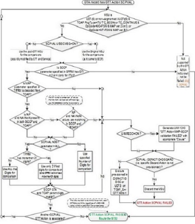
SFAPP GTT Action
The SFAPP GTT action diverts the translated MSU to the SFAPP card.
Figure 2-20 Forward SFAPP GTT Action Entry
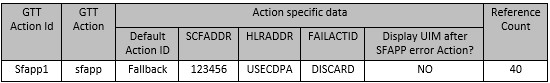
The user is able to provision SFAPP card information in the SFAPP GTT Action entry through SCFADDR. HLRADDR is used later on the SFAPP card.
The SFAPP GTT Action is controlled by the "GTT Action - SFAPP" parameter.
Figure 2-21 SFAPP Action Processing
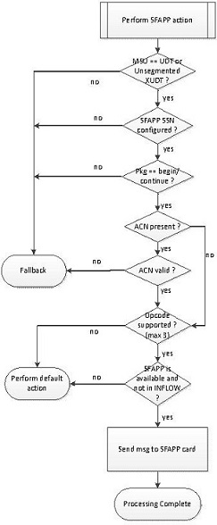
GTT Action Set
A GTT action set contains from one to six GTT action entries, the GTT action set ID which is used by global title address entries to reference the GTT action set, a test mode field whose value can be either on or off, and a reference count. The EAGLE can contain 20,000 GTT action sets.
A GTT action set is assigned to a global title address
entry. The reference count in the GTT action set shows the number of global
title address entries that reference the GTT action set. When a GTT action set
is referenced by an global title address entry, the reference count is
increased by 1. When a global title address entry no longer references the GTT
action set, the reference count is decreased by 1. The GTT action set can be
removed only when the reference count is zero. When the GTT action set is
removed, the reference counts of GTT action entries that are in the GTT action
set are decreased by 1.The data for each GTT action set is shown in the
rtrv-gttaset
output.
ent-gttaset command with these
parameters.
actsn- the GTT action set nameactid1- The GTT action entry ID shown in thertrv-gttactoutput.actid2- The GTT action entry ID shown in thertrv-gttactoutput.actid3- The GTT action entry ID shown in thertrv-gttactoutput.actid4- The GTT action entry ID shown in thertrv-gttactoutput.actid5- The GTT action entry ID shown in thertrv-gttactoutput.actid6- The GTT action entry ID shown in thertrv-gttactoutput.-
on=testmode -
off=testmode
- The Forward, Discard, UDTS, TCAP Error and Services GTT Actions are mutually exclusive in a GTT Action Set.
- No GTT Action is allowed to repeat in a GTT Action Set. However, the GTT Action Set can contain multiple Duplicate GTT Actions and a maximum of 2 SCPVAL GTT Actions with different Action Ids.
- The GTT action set must contain at least one GTT action entry.
- The GTT action set Id must be unique in the GTT action set table.
- The user can provision a maximum of 5 Duplicate Actions and one of Forward/Discard/UDTS/TCAP Error/Services/SFLOG/SFTHORT and maximum of 2 SCPVAL Actions per Action Set.
- The user can provision a maximum of 2 SCPVAL Actions and one of Forward/Discard/UDTS/TCAP Error/Services/SFLOG/SFTHROT Actions or multiple Duplicate's per Action Set. The SPRAM and TPRM combination for both the SCPVAL GTT Actions in the same action set must be unique.
- The SFTHROT GTT Action will be the first GTT Action in a GTT Action Set. No GTT Action is allowed before this action in a GTT Action set.
- The GTT action entries can be provisioned in any order
in the GTT action set as long as the GTT action entry that contains either the
Forward, Discard, UDTS, TCAP Error, Services, SFLOG, SFTHROT GTT or SCPVAL
action is the last entry in the GTT action set. For example, the
actid4parameter can be specified without specifying theactid1parameter. However, after specifying theactid4parameter with a Duplicate GTT action entry, theactid1parameter cannot be specified with a GTT action entry that contains either the Forward, Discard, UDTS, TCAP Error, Services, SFLOG, SFTHROT or SCPVAL GTT action. Another Duplicate GTT action entry can be specified for theactid1parameter. - The user can provision only one SFAPP action. It is supported with Duplicate, Services, SFLOG and SFTHROT GTT Actions. It can only be the last GTT action in the action set.
- Forward
- Discard
- UDTS
- TCAP Error
- Services
- SFTHROT
- SFLOG
- SCPVAL
- SFAPP
- Duplicate (a maximum of 5 Duplicate Action Ids)
- Duplicate (a maximum of 5 Duplicate GTT Actions)/SLFOG/SCPVAL (a maximum of 2 SCPVAL GTT Actions), Discard (the last entry in the GTT action set)
- Duplicate (a maximum of 5 Duplicate GTT Actions)/SLFOG/SCPVAL (a maximum of 2 SCPVAL GTT Actions), UDTS (the last entry in the GTT action set)
- Duplicate (a maximum of 5 Duplicate GTT Actions)/SLFOG/SCPVAL (a maximum of 2 SCPVAL GTT Actions), TCAP Error (the last entry in the GTT action set)
- Duplicate (a maximum of 5 Duplicate GTT Actions)/SLFOG/SCPVAL (a maximum of 2 SCPVAL GTT Actions), Forward (the last entry in the GTT action set)
- SFTHROT, any other GTT Action
- Duplicate, SFLOG and SCPVAL GTT Actions can come in any order
- Duplicate (a maximum of 5 Duplicate GTT Actions)/SFLOG/Services/SFTHROT and SFAPP (in the same order)
on=testmode- indicates that the GTT action set is used only by the test message tool.off=testmode- indicates that the GTT action set is used for real-time MSU processing.
The default value for the test mode field, if neither the
on=testmode or
off=testmode parameters are specified,
is
off.
GTA Entries and the Discard/UDTS/TCAP Error GTT Action
In previous releases, only the Discard and UDTS GTT actions could be assigned to a GTA entry, but the GTA entry could contain no routing data (the point code, SSN, routing indicator, MRN set and MAP set values). With the GTT Actions feature, the GTA entry that references the GTT action set that contains the Discard, UDTS, or TCAP Error GTT actions can contain routing data, although the routing data is not used during message processing. This allows the user to change the GTT action set that is being referenced by the GTA entry to a GTT action set that requires routing data, a GTT action set that contains either the Duplicate or Forward GTT actions, without having to provision the routing data for the GTA entry.
GTA Entries with the XLAT=NONE Parameter
In previous releases, the Discard and UDTS GTT actions
were specified for the GTA entry with the
xlat=disc and the
xlat=udts parameters of the
ent-gta or
chg-gta commands. The GTT Actions
feature allows a GTA entry to be provisioned with the
xlat=none parameter. The GTA entry that
contains the
xlat=none parameter can contain any data
except the routing data (the point code, SSN, and routing indicator). At any
point of time, in a given GTT set, two GTA entries with same GTA value and
different XLAT values are not allowed.
xlat=none parameter value is found,
these actions occur.
- For successful non-GTT Message Relay Services, the MSU continues to use the routing data from the EPAP service or PPSOPTS table. If a GTT action set is associated with the matched translation, then the GTT actions in the GTT action set is applied to the MSU.
- For all other MSUs:
- If the matching translation that contains the
xlat=noneparameter value and a GTT action set and:- The GTT action set contains only one of these actions: Discard, UDTS, or TCAP Error GTT Action, then the matching translation is considered a match.
- The GTT action set that contains the Duplicate or Forward GTT actions, then the matching translation is not considered a match.
- If a matching translation that contains the
xlat=noneparameter value and does not contain a GTT action set, the matching translation is not considered a match because there is no routing data. If none of the following conditions are present, the global title translation process has failed.- If the Support for 16 GTT Lengths in VGTT
feature is not enabled and turned on, the global title translation process may
find the best match with a lesser number of digits that contains an
xlatparameter value other thannone. - While searching for a matching translation
using the Origin-Based SCCP Routing feature:
- For the advanced CdPA Mode, the translation
containing the
xlat=noneparameter value is found in the advanced portion of CdPA translation, (SELID, OPTSN, or OPCSN), and no further advanced CdPA processing is possible (for example, there is no optional OPCSN defined), the next GTT mode in the GTT hierarchy is considered. - For all other modes:
- If there is no previously matched translation, the next GTT mode in the GTT hierarchy is considered, if the GTT mode is available.
- If there is previously matched translation, the MSU is routed according to the data in the previously matched translation.
For example, while searching for a matching translation using the Origin-Based SCCP Routing feature, Set 3 Translation is found (see Figure 2-22). A matching translation that contains the
xlat=noneparameter value is found in SELID/Set 4. This is not considered a match. The MSU is routed based on the routing data in Set 3 Translation.If Set 3 Translation is a CdPA GTA translation with an optional OPC set and a matching translation that contains the
xlat=noneparameter value is found in SELID/Set 4, and a matching translation that contains thexlat=noneparameter value is found in the OPC set also, the next mode in the GTT hierarchy is selected.Figure 2-22 Origin-Based SCCP Routing and XLAT=NONE
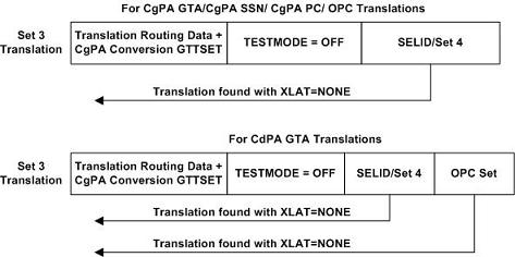
- For the advanced CdPA Mode, the translation
containing the
- If the Support for 16 GTT Lengths in VGTT
feature is not enabled and turned on, the global title translation process may
find the best match with a lesser number of digits that contains an
- While searching for a matching translation using
the Flexible Linkset Optional Based Routing feature, if a translation that
contains the
xlat=noneparameter value is encountered, the FALLBACK option of the previously found translation is used. If the FALLBACK option is set to yes, a match is made to the previously found translation. If the FALLBACK option is set to no, the global title translation process has failed. For example, while searching for a matching translation using the Flexible Linkset Optional Based Routing feature, Set 1 Translation is found (see Figure 2-23). A matching translation that contains thexlat=noneparameter value is found in SELID/Set 2.This is not a match. The FALLBACK option of Set 1 Translation is used. Since the FALLBACK option is set to yes in Set 1 Translation, the MSU is routed based on the Set 1 Translation routing data.Figure 2-23 Interaction between the FALLBACK Option and XLAT=NONE
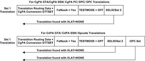
If Set 1 Translation is a CdPA GTA, CdPA SSN, or Opcode translation and a matching translation that contains the
xlat=noneparameter value is found in SELID/Set 2 as shown in Figure 2-22, a check for a matching translation is made in the OPC set. If a matching translation that contains thexlat=noneparameter value is found in the OPC set, the FALLBACK option of Set 1 Translation is used. Since the FALLBACK option in Set 1 Translation is set to yes, the MSU is routed based on the Set 1 Translation routing data. If Set 1 is the very first GTT set that is found in the searching process and Set 1 Translation is provisioned with thexlat=noneparameter value, then the global title translation process fails. - For opcode translations, the global title translation process used the TCAP Opcode Based Routing feature to find the best matching translation.
- If the matching translation that contains the
GTT Action Per-TT Measurements
GTT action-related events recorded by the SCCP application are reported as system-wide totals, on a per-translation type basis (per-TT), and a per-path basis. The events recorded for GTT Actions are shown in Table 2-19 and Table 2-20.
Table 2-19 GTT Action Events Recorded for Per-TT and System-Wide Measurements Reports
| Event Label | Description |
|---|---|
| GTTASET | The total number of messages receiving any GTT action. |
| GTTADUP | The total number of messages for which a Duplicate MSU was sent. |
| GTTADISC0 | The total number of messages discarded by the DISCARD GTT action. |
| GTTADISC1 | The total number of messages discarded by the UDTS GTT action. |
| GTTADISC2 | The total number of messages discarded by the TCAP Error GTT action. |
| GTTAFWD | The total number of messages forwarded by the Forward GTT action. |
| GTTASRVGFLX | The total number of messages serviced by GFLEX GTT Action. |
| GTTASRVGPRT | The total number of messages serviced by GPORT GTT Action. |
| GTTASRVSMSR | The total number of messages serviced by SMSMR GTT Action. |
Table 2-20 GTT Action Events Recorded for Per-Path Measurements Reports
| Event Label | Description |
|---|---|
| GTTACTNA | The total number of messages for which no GTT actions were performed. |
| GTTADUP | The total number of messages for which a Duplicate MSU was sent. |
| GTTADISC0 | The total number of messages discarded by the DISCARD GTT action. |
| GTTADISC1 | The total number of messages discarded by the UDTS GTT action. |
| GTTADISC2 | The total number of messages discarded by the TCAP Error GTT action. |
| GTTAFWD | The total number of messages forwarded by the Forward GTT action. |
| GTTASRVGFLX | The total number of messages serviced by GFLEX GTT Action. |
| GTTASRVGPRT | The total number of messages serviced by GPORT GTT Action. |
| GTTASRVSMSR | The total number of messages serviced by SMSMR GTT Action. |
The per-translation type report contains a breakdown of the GTT action events for each of the translation types provisioned in the database, up to a maximum of 256 translation types. This data is available for every 30-minute interval, and for every 15-minute interval if the 15-Minute Measurements feature is enabled and turned on. The GTT Actions system-wide measurements report provides the totals of all the actions that were performed on the EAGLE for all the GTT action sets. This report is available for every 30-minute interval, and for every 15-minute interval if the 15-Minute Measurements feature is enabled and turned on.
GTT Action Per-Path Measurements
The GTT action per-path measurements provides measurement
counts for the GTT actions applied to the messages that match a pre defined
combination of “CgPA GTA”, “CdPA GTA”, and “Opcode” values. The combination of
these values are provisioned in the GTT Path table with the
ent-gttapath command. Each entry in the
GTT Path table must be unique combination of CdPA GTA, CgPA GTA and Opcode
values and this combination is called a path. If a translation search in Global
Title Translation table matches the path specified in GTT Path table, then the
corresponding measurement counts for that path are incremented. However, if the
ppmeasreqd parameter (Per Path
Measurements required) value for the final translation is
no, then the per-path measurement counts
for the matching path are not pegged.
ent-gttapath command with these
parameters.
gttpn- the GTT action path nameopgttsn- the opcode GTT set name shown in thertrv-gttsetoutput.opcode- the opcode value shown in thertrv-gtaoutput that is assigned to theopgttsnvalue.pkgtype- the package type value shown in thertrv-gtaoutput that is assigned to theopgttsnvalue.family- the family value shown in thertrv-gtaoutput that is assigned to theopgttsnvalue.acn- the ACN value shown in thertrv-gtaoutput that is assigned to theopgttsnvalue.cggttsn- the CGGTA GTT set name shown in thertrv-gttsetoutput.cggta- the CGGTA shown in thertrv-gtaoutput that is assigned to thecggttsnvalue.cdgttsn- the CDGTA GTT set name shown in thertrv-gttsetoutput.cdgta- the CDGTA shown in thertrv-gtaoutput that is assigned to thecggttsnvalue.
An example of a GTT action path entry is shown in Figure 2-24.
Figure 2-24 GTT Action Path Entry
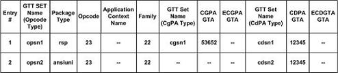
The GTT Action path table can contain a maximum of 10,000
entries. A GTT path entry shall have up to three GTT set-value combinations in
it, where the GTT set and value must be a valid entry in the GTT Translation
table. However, a GTT path must be provisioned with at least one GTT set and
value (CdPA GTA/CgPA GTA/Opcode). For every GTT action path, the GTT set and
the value must be specified together as a combination. If the GTT Set-value
combination is not provisioned in a GTT action path then it is considered as no
value and is displayed as “----“ in the
rtrv-gttapath output for that
combination. Translation entries cannot be removed or modified (in case of GTA
range splitting) if the entries are referenced in a GTT action path.
Figure 2-25
shows the relation between the two tables.
Figure 2-25 GTT Translation and GTT Action Path Table Relationship
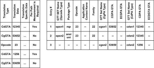
The GTT actions per-path measurements report contains the GTT Action events for the predefined GTT paths that are provisioned in the database, up to a maximum of 10,000 predefined paths. The per-path measurement data is collected during the 60 minute interval period (per hour). The hourly data is retained for 24 hours. The daily collection data is retained for seven days. The data collection reports are available as both scheduled and on-demand reports. The events recorded for the GTT actions per-path measurements is shown in Table 2-20.
- A matching global title translation was found for at least one of the CdPA GTA/ CgPA GTA/ Opcode values.
- The
ppmeasreqdparameter value in the global title translation isyes. - The matching CdPA GTA/ CgPA GTA/ Opcode translation combination is provisioned in GTT action path table.
GTT Action Path Entry Searched with all the GTT Set-Value Combinations Specified
All three specified GTT Set-value combinations (opcode/CgPA/CdPA) are provisioned in a GTT action path in GTT action path table as shown in Figure 2-26.
Figure 2-26 Example GTT Action Path Table Entry
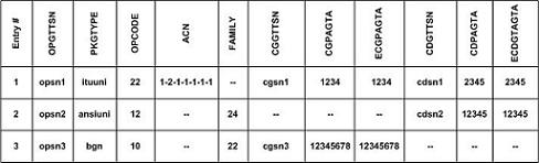
- The
ppmeasreqdparameter value in the global title translation isyes. - All the specified GTT set-value combinations were searched in any order during the global title translation lookup.
Figure 2-27 GTT Translation Lookup - Exact GTT Action Path Match
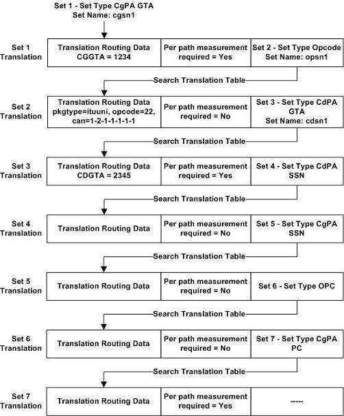
- Set 1 - CGGTTSN = cgsn1 - CGGTA = 1234
- Set 2 - OPGTTSN = opsn1 - Opcode = 22
- Set 3 - CDGTTSN = cdsn1 - CDGTA = 2345
This combination matches the entry # 1 in the GTT action path table shown in Figure 2-26. Since the per-path measurement required value is set to Yes in Set 7 (the translation result), entry #1 in Figure 2-26 is pegged in the per-path measurements report. If the per-path measurement required value is set to No in Set 7, then entry #1 in Figure 2-26 is not pegged in the per-path measurements report.
GTT Action Path Entry Not Searched in the Translation Lookup
If a GTT set-value combinations search is performed during the translation lookup, and all the searched combinations do not match any of the provisioned GTT action paths, then the per-path measurements are not pegged.
Figure 2-28 GTT Translation Lookup - No GTT Action Path Match
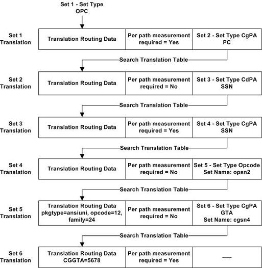
In Figure 2-28, a search is performed for this translation data during the global title translation lookup. CDPA GTA and CgPA GTA searches were not performed.
| Opcode GTT Set Type | Set 5 | OPGTTSN=opsn2 | OPCODE=12 |
The entries in Figure 2-26 do not contain any entries that have only an Opcode entry, so the per-path measurements are not pegged.
GTT Path Entry Searched with Some GTT Set-Value Combinations Specified
- The per-path measurement required value in the resulting translation is set to Yes.
- The matching translation entry was found for both the CgPA and Opcode GTT set-value combination.
- Either the search was not performed on CdPA GTA or no matching translation entry was found for the CdPA GTA.
Figure 2-29 GTT Translation Lookup - Exact GTT Action Path Match (with Unspecified GTT Set-Value Combinations)
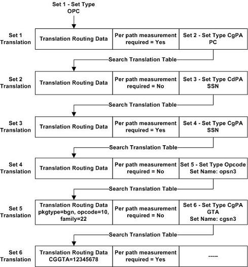
In Figure 2-29, searches are performed for this translation data during the global title translation lookup. CDPA GTA search was not performed
| Opcode GTT Set Type | Set 5 | OPGTTSN=opsn3 | OPCODE=10 |
| CGPA GTT Set Type | Set 6 | CGGTTSN=cgsn3 | CGGTA=12345678 |
The searched CGPA GTA/CdPA GTA/OPCODE values matches Entry #3 in Figure 2-26 where the CDPA GTA is provisioned as none. Since the per-path measurement required value is set to Yes in Set 6 (the translation result), entry #3 in Figure 2-26 is pegged in the per-path measurements report.
Provisioning the GTT Actions Feature
To provision the GTT Actions feature, perform these steps.
- Turn the GTT and EGTT features on using the
chg-featcommand. Add the required service modules to the database using theent-cardcommand. Perform the Adding a Service Module procedure. - Enable and turn on one or more of these features using
the
enable-ctrl-featand thechg-ctrl-featcommands.- To perform the GTT actions Discard, UDTS, or TCAP Error - GTT Action – DISCARD – 893027501
- To perform the GTT action Duplicate - GTT Action – DUPLICATE – 893027601
- To perform the GTT action Forward - GTT Action – FORWARD – 893037501
Perform the Activating the GTT Actions Features procedure to enable and turn on these features.
- Provision the required GTT actions using the
ent-gttactcommand by performing the Adding a GTT Action procedure. - Provision the required GTT action sets using the
ent-gttasetcommand by performing the Adding a GTT Action Set procedure. - Provision the required GTT translations using the
ent-gtacommand. Perform Adding Global Title Address Information.
To provision the GTT action paths, perform these steps.
- Perform the
Activating the GTT Actions Features
procedure to enable and turn on these features.
- To perform the GTT actions Discard, UDTS, or TCAP Error - GTT Action – DISCARD – 893027501
- To perform the GTT action Duplicate - GTT Action – DUPLICATE – 893027601
- To perform the GTT action Forward - GTT Action – FORWARD – 893037501
- Provision the required GTT sets using the
ent-gttsetcommand. Perform Adding a GTT Set. - Provision the required GTT translations using the
ent-gtacommand. Perform Adding Global Title Address Information. - Provision the required GTT action paths using the
ent-gttapathcommand by performing the Adding a GTT Action Path Entry procedure.
Support for CAT2 SS7 Security
Note:
The IR.21 document contains operator wise network information such as, MCC-MNC, Node GT (HLR/VLR/MSC), and CC-NDC.The CAT2 SS7 security functionality is achived using the CAT2 Utility. This utility is external to EAGLE and can be downloaded from the Oracle Software Delivery Cloud along with the other EAGLE components.
The CAT2 Utility is used for reading and recording the information present in GSMA IR.21 document into database tables. The SCPVAL GTT Action addresses the SS7 CAT2 security checks. This GTT action ensures that the MSU details such as, CgPA and IMSI belongs to same operator after validating it with the newly generated table.
CAT2 SS7 Security Workflow
The following flow chart provides an overview of the CAT2 SS7 Security functionality:
Figure 2-30 CAT2 SS7 Security Workflow

- The IR.21 XML file is parsed on a linux machine using the external CAT2 Utility. The utility extracts the information required from the IR.21 file for validation of the message and convert the data in tabular format to be used in EAGLE.IR.21 input file in XML format and generate error message in case of no or other than IR.21 XML files.
- The output is generated in
CAT2IMSIandCAT2GTAtables and the network card supporting SCCP functionality gets updated along with table data.The following data is extracted from IR.21 file and stored on EAGLE:- Sender TADIG code (RAEX IR.21 Information) : It is retrieved from the RAEX IR.21 FileHeader tag and used to identify the operator. It consist of two fields, with a total length of five characters consisting of three-character country code and a two character operator or company idenfier. Sender TADIG code is stored against each entry in both the tables.
- Routing Information Data (Section ID 4) : It is a
mandatory section in IR.21 document of the operator. The EAGLE
CAT2IMSItable stores the MCC-MNC (E.212) along with TADIG code from this section. The EAGLECAT2GTAstores the CC-NC (from E.214) along with TADIG code from this section. - Network Element Information Data (Section ID 13) –
It is an optional section in IR.21 document of the operator. The
EAGLE
CAT2GTAtable stores the HLR Node type GT address or Address range along with the TADIG code from this section.
- The SCPVAL GTT action validates that the MSU details: CgPA and IMSI belongs
to same operator. The validation is based on the following two rules:
- The IMSI within MAP layer of a message must match with the IMSI prefixes (MCC + MNC) of the protected network.
- The OperatorID (TADIG code) referenced by all parameters in the MAP
layer of the message (IMSI and HLR) must match with the OperatorID
referenced by the matching IR.21 nodal GT ranges.
The MSUs that passes these rules are considered as free from CAT2 anomalies.
All the supported Category 2 Opcodes are screened with these rules. If the first rule passes, then only MSU validates for the second rule. Otherwise, the SCPVAL GTT Action is considered as failure.
Considerations for Validation
-
The following Opcodes are applicable for CgPA and IMSI validation:
- ProvideRoamingNumber (4)
- ProvideSubscriberInformation (70)
- ProvideSubscriberLocation (83)
- CancelLocation (3)
- InsertSubscriberData (7)
- DeleteSubscriberData (8)
- Reset (37)
- ActivateTraceMode (50)
- UnstructuredSS-Request (60)
- UnstructuredSS-Notify (61)
- AlertServiceCentre (64)
- SetReportingState (73)
- IstCommand (88)
- RemoteUserFree (75)
-
The IMSI has upto 15 digits value. The value is composed of three parts:
- Mobile Country Code (MCC): Consists of 3 digits
- Mobile Network Code (MNC): Consists of 2 or 3 digits
- Mobile Subscriber Identification Number (MSIN): 9 or 10 digits
The MCC and MNC parameters (first 5-6 digits) determine the Operator ID. Hence, these values are used during CAT2 validation.
At first, the match is performed with 6 digit, and if the match is not found, then it is performed with 5 digits. In case, the match is not found, the validation gets failed.
MTP Routed Global Title Translation
In previous releases, MTP routed SCCP messages are routed to the service module if either the MTP Msgs for SCCP Apps feature, part number 893017401, is enabled and turned on, or the MSU is screened by the Gateway Screening stop action SCCP. These actions were performed on the service modules
- EPAP service handling is performed.
- If the EPAP service handling resulted in Fall through to MTP routing, then MTP Routed GSM MAP Screening is performed, if applicable.
- The MSU is MTP routed if the message is not discarded by MTP Routed GSM MAP Screening.
In addition to the actions that were performed in previous releases, global title translation and GTT Actions are performed on MTP routed MSUs similar to the existing global title translation GTT handling for GT routed MSU’s. Global title translation on MTP routed MSUs is performed if the service handling results in Fall through to GTT or if the GTT required option in the service selector is set to on for the service relayed MSU.
mtprgtt which specifies whether global title translation is performed on an MTP routed MSU and the routing that is performed on the MSU after global title translation is performed. The mtprgtt parameter is contains these values.
off- global title translation is not performed on the MTP routed MSU.usemtppc- global title translation is performed on the MTP routed MSUs and the MSU is sent to the original DPC.fullgtt- global title translation is performed on the MTP routed MSU and the MSU is sent to the translated DPC.
mtprgttfallbk which specifies whether an MTP routed MSU is MTP routed after the failure of the global title translation process.
mtproute- perform MTP routing on the MSU if a failure occurs during the global title translation process.gttfail- discard the MSU if a failure occurs during the global title translation process. Send a UDTS message if required.
Unique GTT Selectors
In previous EAGLE releases that did not support the Unique GTT Selectors feature, all ITU GTT selectors shared the same space in the GTT selector table. Only one entry for an ITU GTT selector that contains a specific GTI and translation type value, regardless of the network type or domain of the ITU GTT selector, could be defined in the GTT selector table. For example, if the GTT selector table contained an ITU-I GTT selector with the GTI value 2 and the translation type value 5, this GTI and translation type value combination could not be assigned to an ITU-N or ITU-N24 GTT selector.
When the EAGLE is upgraded from a release that did not support the Unique GTT Selectors feature to a release that does support the Unique GTT Selectors feature, the ITU GTT selectors created in the previous release become overlapped GTT selectors.
- ITU-I spare and ITU-N spare GTT selectors
- Provisioning the same translation type and GTI values for ITU GTT selectors of all network types including the ITU-I spare and ITU-N spare network types.
- GTT selectors of all network types including ITU-I spare and ITU-N spare network types that contain the GTI value 0 (zero).
In a release that does support the Unique GTT Selectors feature, the user is able to add more GTT Selectors for the existing overlapped GTT Selector as long as the GTIx (ITU domain only) and TT combination matches the existing overlapped GTT Selector.
The user will not be able to add a new non-overlapped GTT selector entry if the GTIx (ITU domain only) and TT combination matches to an existing overlapped GTT Selector entry created during upgrade to a release that supports the Unique GTT Selectors feature from a release that did not support it. The unqgttsel parameter in the SCCPOPTS table controls run-time behavior of the Unique GTT Selector feature; when it is set to "exactmatch," overlapped entries will behave as non-overlapped entry.
Any new entries added in a release that supports the Unique GTT Selectors feature, with the GTIx and TT combination that were not present in the system while upgrading to a release that supports the Unique GTT Selectors feature, will be added as non-overlapped entries.
The provisioning of ITU-I spare and ITU-N spare GTT
selectors is the same as provisioning ITU-I and ITU-N GTT selectors. This
includes the provisioning of default GTT selectors using the
ent-tt command. For more information
about using the
ent-tt command to provision default GTT
selectors, see the
Adding a Translation Type
procedure.
GTT Selectors with the GTI Value of 0
With the Unique GTT Selectors feature, The EAGLE can
process MSUs whose GTI value is 0 (a GTI=0 GTT selector) for all network types,
including ITU-I spare and ITU-N spare. A GTI=0 GTT selector cannot contain
tt,
np,
nai, and
Eagle-Gen values. A GTI=0 GTT selector
can contain
lsn (the name of a linkset),
selid, and
cgssn values. The values that can be
specified for a GTI=0 GTT selector is determined by the features that are
enabled and turned on.
GTT Selector Key for GTI=0 GTT Selectors
Table 2-21 defines the keys in the GTT selector table based on the feature combination for GTI=0 GTT selectors. If a feature supports specific parameters and that feature is not enabled or turned on, then default values are entered into the database for those parameters.
Table 2-21 GTT Selector Key for GTI=0
| Feature Combination | Selector Type | GTI, Domain | CgPA SSN | SELID | Link Set Name |
|---|---|---|---|---|---|
| EGTT | CdPA Only | X | - | - | - |
| Origin-Based SCCP Routing | CdPA | X | - | - | - |
| CgPA | X | X | X | - | |
| Flexible Linkset Optional Based Routing | CdPA | X | - | X | X |
| CgPA | X | - | X | X | |
| Origin-Based SCCP Routing and Flexible Linkset Optional Based Routing | CdPA | X | - | X | X |
| CgPA | X | X | X | X |
Searching Order for GTI=0 GTT Selectors
Table 2-22 and Table 2-23 shows the searching order for CdPA and CgPA GTI=0 GTT Selectors.
Table 2-22 Searching Order for CdPA GTI=0 GTT Selectors
| CdPA GTT Selector Keys | ||||
|---|---|---|---|---|
| Priority | GTA, Domain | Linkset ID | SELID | CdPA GTT Selector Found or Not Found |
| 1 | Exact | Exact | Exact |
If a meaningful CdPA GTT set is provisioned, then the GTT selector is considered found. If a meaningful CdPA GTT set is not provisioned, then the GTT selector is considered not found. |
| 2 | Exact | Any | Exact | |
Table 2-23 Searching Order for CgPA GTI=0 GTT Selectors
| CgPA GTT Selector Keys | |||||
|---|---|---|---|---|---|
| Priority | GTA, Domain | Linkset ID | SELID | CgPA SSN | CgPA GTT Selector Found or Not Found |
| 1 | Exact | Exact | Exact | Exact |
If a meaningful CgPA GTT set is provisioned, then the GTT selector is considered found. If a meaningful CgPA GTT set is not provisioned, then the GTT selector is considered not found. |
| 2 | Exact | Exact | Exact | Any | |
| 3 | Exact | Any | Exact | Exact | |
| 4 | Exact | Any | Exact | Any | |
| 5 | Exact | Any | Any | Any | |
For the Origin-Based SCCP Routing feature GTT hierarchy, meaningful means following the Origin-Based SCCP Routing feature rules; the GTT set type of a CdPA GTT set must be CDGTA and the GTT set type of a CgPA GTT set must be either CGGTA or CGPC. If a Flexible Linkset Optional Based Routing feature GTT hierarchy is being used, then any GTT set type can be used.
The Linkset ID, SELID, and CGSSN parameters are controlled by the Flexible Linkset Optional Based Routing and Origin-Based SCCP Routing features. If a parameter is not allowed, it assumes the value of Any in the database. In Table 2-22 and Table 2-23, if a parameter is specified as Exact and that parameter is not allowed, then the Exact value is the same as the Any value.
Using the Unique GTT Selectors Feature
unqgttsel parameter of the
chg-sccpopts command is used. The
unqgttsel parameter contains these
values.
bestmatch- search for overlapped GTT selectors if non-overlapped GTT selectors are not found.exactmatch- search only for non-overlapped GTT selectors.
unqgttsel parameter is applied to GTIx=2
and GTIx=4 GTT selectors, these actions occur.
- When the
unqgttselparameter value isbestmatch:- A non-overlapped GTT selector is matched, if it is in the database, using the searching rules defined by the EGTT, Origin-Based SCCP Routing features, Flexible Linkset Optional Based Routing, and TCAP Opcode Based Routing features.
- If a non-overlapped GTT selector is not found, an overlapped GTT selector is matched, if it is in the database, using the searching rules defined by the EGTT, Origin-Based SCCP Routing features, Flexible Linkset Optional Based Routing, and TCAP Opcode Based Routing features.
- If a matching non-overlapped or overlapped GTT selector is not found, the search fails.
- When the
unqgttselparameter value isexactmatch:- A non-overlapped GTT selector is matched, if it is in the database.
- If a matching non-overlapped GTT selector is not found, the search fails.
unqgttselparameter is applied to GTIx=0
GTT selectors, these actions occur.
- When the
unqgttselparameter value isbestmatch:- An exact GTIx=0 GTT selector is matched, if it is in the database, using the searching order shown in Table 2-22 and Table 2-23.
- If an exact GTIx=0 GTT selector match is not found, an overlapped GTT selector (ANSI and ITU-I network types only) is matched, if it exists, using the searching order shown in Table 2-22 and Table 2-23.
- If an exact GTIx=0 GTT selector match is not found and an overlapped GTT selector is not found, the search fails.
- When the
unqgttselparameter value isexactmatch:- An exact GTIx=0 GTT selector is matched, if it is in the database, using the searching order shown in Table 2-22 and Table 2-23.
- If an exact GTIx=0 GTT selector match is not found, the search fails.
The
unqgttsel parameter value can be changed
at any time. Non-overlapped GTT selectors can be provisioned regardless of the
unqgttsel parameter value. When there
are no overlapped GTT selectors in the database and only non-overlapped GTT
selectors are in the database, the
exactmatch value of the
unqgttsel parameter is applied to the
GTIx=2 and GTIx=4 GTT selectors. The system default value of the
unqgttsel parameter is
bestmatch.
XUDT UDT Conversion Feature
- An XUDT(S) message to a UDT(S) message
- A UDT(S) message to an XUDT(S) message
The conversion is performed on a service module card if the message was generated by the EAGLE, or on a LIM receiving the message if the message is MTP-routed. The conversion takes place just before the message is sent to the LIM that will be transmitting the message out of the EAGLE.
An SCCP Class 1 message that requires SCCP processing is processed by a service module card and then sent back to the receiving LIM to maintain sequencing. Message routing and the XUDT(S) UDT(S) conversion is performed on the receiving LIM in this case.
- The XUDT UDT Conversion feature must be enabled and turned on – perform the Activating the XUDT UDT Conversion Feature procedure.
- Configure the destination point code of the XUDT(S) or
UDT(S) message using either the
ent-dstnorchg-dstncommands and specifying thesccpmsgcnvparameter. Perform one of these procedures in Database Administration – SS7 User's Guide.- Adding a Destination Point Code
- Adding a Cluster Point Code
- Adding a Network routing Point Code
- Changing a Destination Point Code
- Changing the Attributes of a Cluster Point Code
Table 2-24 shows the values of the
sccpmsgcnvparameter.Table 2-24 SCCPMSGCNV Parameter Values
SCCPMSGCNV Parameter Value Parameter Description NONE No conversion is performed on messages for the destination. This is the default value of the sccpmsgcnvparameter if thesccpmsgcnvparameter is not specified with theent-dstncommand.SXUDT2UDT All segmented XUDT(S) and non-segmented XUDT messages for the destination are converted to UDT(S) messages. XUDT2UDT All non-segmented XUDT(S) messages for the destination are converted to UDT(S) messages. Segmented XUDT(S) messages are be converted to UDT(S) messages. All non-segmented XUDT(S) messages for the destination are converted to UDT(S) messages. Segmented XUDT(S) messages are not converted. UDT2XUDT All UDT(S) messages are converted to XUDT(S) messages.
UDT(S) to XUDT(S) Conversion
When converting a UDT(S) message to an XUDT(S) message, the changes shown in Table 2-25 are made to the message.
If the SCCP portion of the pre-converted message is longer that 270 bytes and the conversion results in the addition of the Hop Counter (1 byte) and Pointer to Optional Parameters (1 byte) fields causing the size of the SCCP portion to increase beyond a length of 272 bytes, then the segmentation of the message is not performed
Table 2-25 Parameter Values after UDT to XUDT or UDTS to XUDTS Conversion
| UDT to XUDT Conversion | UDTS to XUDTS Conversion | ||
|---|---|---|---|
| Parameter | Value after UDT to XUDT Conversion | Parameter | Value after UDTS to XUDTS Conversion |
| Message Type | XUDT (0x11) | Message Type | XUDTS (0x12) |
| Protocol Class | Same as the pre-converted message. | Return Cause | Same as the pre-converted message. |
| Hop Counter | 15, which is the maximum value. | Hop Counter | 15, which is the maximum value. |
| Pointer to Called Party Address (CDPA) | Incremented from the pre-converted UDT message value by the size of the Pointer to Optional Parameters value (1 byte). | Pointer to Called Party Address (CDPA) | Incremented from the pre-converted UDTS message value by the size of the Pointer to Optional Parameters value (1 byte). |
| Pointer to Calling Party Address (CGPA) | Incremented from the pre-converted UDT message value by the size of the Pointer to Optional Parameters value (1 byte). | Pointer to Calling Party Address (CGPA) | Incremented from the pre-converted UDTS message value by the size of the Pointer to Optional Parameters value (1 byte). |
| Pointer to Data | Incremented from the pre-converted UDT message value by the size of the Pointer to Optional Parameters value (1 byte). | Pointer to Data | Incremented from the pre-converted UDTS message value by the size of the Pointer to Optional Parameters value (1 byte). |
| Pointer to Optional Parameters | 0, since no optional parameters are present in a converted XUDT message. | Pointer to Optional Parameters | 0, since no optional parameters are present in a converted XUDTS message. |
| Called Party Address (CDPA) Parameter | Same as the pre-converted message. | Called Party Address (CDPA) Parameter | Same as the pre-converted message. |
| Calling Party Address (CGPA) Parameter | Same as the pre-converted message. | Calling Party Address (CGPA) Parameter | Same as the pre-converted message. |
| Data | Same as the pre-converted message. | Data | Same as the pre-converted message. |
XUDT(S) to UDT(S) conversion
When converting an XUDT(S) message to a UDT(S) message, the changes shown in Table 2-26 are made to the message.
If the
sccpmsgcnv value for the destination
is
xudt2udt, only non-segmented XUDT(S)
messages are converted to UDT(S) messages while segmented XUDT(S) messages,
that is, messages that contain the Segmentation parameter are routed to the
destination without being converted.
If the
sccpmsgcnv value for the destination
is
sxudt2udt, both segmented and
non-segmented XUDT(S) messages are converted to UDT(S) messages.
Table 2-26 Parameter Values after XUDT to UDT or XUDTS to UDTS Conversion
| XUDT to UDT Conversion | XUDTS to UDTS Conversion | ||
|---|---|---|---|
| Parameter | Value after XUDT to UDT Conversion | Parameter | Value after XUDTS to UDTS Conversion |
| Message Type | UDT (0x09) | Message Type | UDTS (0x0a) |
| Protocol Class | Same as the pre-converted message. | Return Cause | Same as the pre-converted message. |
| Hop Counter | Dropped from the converted message. | Hop Counter | Dropped from the converted message. |
| Pointer to Called Party Address (CDPA) | Decremented from the pre-converted (XUDT) message value by the size of the Pointer to Optional Parameters value (1 byte). | Pointer to Called Party Address (CDPA) | Decremented from the pre-converted (XUDTS) message value by the size of the Pointer to Optional Parameters value (1 byte). |
| Pointer to Calling Party Address (CGPA) | Decremented from the pre-converted (XUDT) message value by the size of the Pointer to Optional Parameters value (1 byte). | Pointer to Calling Party Address (CGPA) | Decremented from the pre-converted (XUDTS) message value by the size of the Pointer to Optional Parameters value (1 byte). |
| Pointer to Data | Decremented from the pre-converted (XUDT) message value by the size of the Pointer to Optional Parameters value (1 byte). | Pointer to Data | Decremented from the pre-converted (XUDTS) message value by the size of the Pointer to Optional Parameters value (1 byte). |
| Pointer to Optional Parameters | Dropped from the converted message. | Pointer to Optional Parameters | Dropped from the converted message. |
| Called Party Address (CDPA) Parameter | Same as the pre-converted message. | Called Party Address (CDPA) Parameter | Same as the pre-converted message. |
| Calling Party Address (CGPA) Parameter | Same as the pre-converted message. | Calling Party Address (CGPA) Parameter | Same as the pre-converted message. |
| Data | Same as the pre-converted message. | Data | Same as the pre-converted message. |
| Segmentation – applies only to a segmented ANSI/ITU XUDT message. | Dropped from the converted message. | Segmentation – applies to a segmented ANSI/ITU XUDTS message. | Dropped from the converted message. |
| Importance – applies only to an ITU XUDT message. | Dropped from the converted message. | Importance – applies only to an ITU XUDTS message. | Dropped from the converted message. |
| INS – applies only to an ANSI XUDT message. | Dropped from the converted message. | INS – applies only to an ANSI XUDTS message. | Dropped from the converted message. |
| MTI – applies only to an ANSI XUDT message. | Dropped from the converted message. | MTI – applies only to an ANSI XUDTS message. | Dropped from the converted message. |
| End of Optional Parameters | Dropped from the converted message. | End of Optional Parameters | Dropped from the converted message. |
Feature Interactions
STP/LAN
Database Transport Access - DTA
Integrated Sentinel/IMF
ANSI/ITU SCCP Conversion
GTT Actions
Even though messages are selected for copying for the STP/LAN feature according to their received, non-converted values, the actual messages that are copied will have been converted since the flag for the STP/LAN feature is set on the incoming signaling link and the actual copy occurs on the outgoing signaling link. This applies to all MTP-routed and SCCP messages that are generated by the EAGLE.
The XUDT UDT Conversion feature does not affect the DTA feature’s functioning. The wrapper message is converted while the encapsulated message, which resides in the wrapper’s data area, is not converted. The destination has to extract and convert the encapsulated message if it wishes to route the encapsulated message back to the EAGLE.
Incoming messages are selected for copying according to their received, non-converted values. Outgoing messages are selected for copying according to their converted values. This applies to both MTP-routed and SCCP messages that are generated by the EAGLE.
The XUDT UDT Conversion feature is applied to MTP-routed SCCP messages that do not reach the service module cards before they are processed by the ANSI/ITU SCCP Conversion feature. For GT-routed messages and MTP-routed SCCP messages that are processed on the service module cards, the XUDT UDT conversion feature is applied after the ANSI/ITU SCCP conversion feature is performed on the message.
The XUDT UDT Conversion feature is applied after the GTT Actions have been performed on the message. This means that if 4 DUPLICATE GTT actions are performed on the message, the XUDT UDT conversion feature is applied separately on all of the duplicated messages.
Upgrading from Global Title Translation (GTT) to Enhanced Global Title Translation (EGTT)
The Enhanced Global Title Translation (EGTT) feature provides enhancements to existing global title translation functions and automatically updates the database when the EGTT feature is turned on. Turning on the EGTT feature overrides the Global Title Translation (GTT) feature. This section provides a high-level summary of feature enhancements, the upgrade process, and upgrade considerations for the GTT and EGTT features.
Note:
Before upgrading to and/or turning on a new feature, make sure you have purchased the feature to be upgraded to and/or turned on. If you are not sure whether you have purchased the feature, contact your Oracle Sales Representative or Account Representative.Enhancements
The Enhanced Global Title Translation (EGTT) feature provides enhancements to existing global title translation functions:
- Increased number of selectors
- For ITU networks, addition of the translated subsystem number (SSN) in the called party address (CDPA) when octet is not equipped
- For ITU networks, inclusion of the originating point code (OPC) in the calling party address (CGPA)
- Capability to delete the global title (GT) in the called party address (CDPA)
- GTAs can be added offline to the EAGLE if the GTT set has not yet been assigned to a GTT selector.
- Aliasing is replaced by assigning multiple GTT selectors to an existing GTT set.
- Automatic upgrade of the database when the EGTT feature is turned on.
Upgrade Considerations
Enabling the Enhanced Global Title Translation (EGTT) feature overrides the Global Title Translation (GTT) feature. The GTT Selector, GTT Set, and GTA commands replace the Translation Type (-TT) and Global Title Translation (-GTT) commands. The SEAS equivalent of these commands will be maintained, mapping to ANSI with GTI of 2.
These commands can be executed when the EGTT feature is turned on, but will only produce CDGTA GTT sets and CDGTA GTT selectors.
ENT-TT– Enter Translation TypeCHG-TT– Change Translation TypeDLT-TT– Delete Translation TypeRTRV-TT– Retrieve Translation TypeENT-GTT– Enter Global Title TranslationCHG-GTT– Change Global Title Translation-
DLT-GTT– Delete Global Title Translation RTRV-GTT– Retrieve Global Title Translation
If the point code that is specified with the
ent-gtt or
chg-gtt commands is an ANSI point code, only a CDGTA GTT selector
entry that contains the translation type and the GTI value 2 will be shown in
the
rtrv-gttsel output. If the point code
that is specified with the
ent-gtt or
chg-gtt commands is an ITU point code, two CDGTA GTT selector entries
will be shown in the
rtrv-gttsel output; one that contains
the translation type and the GTI value 2 and another entry that contains the
translation type and the GTI value 4. The CDGTA GTT sets and CDGTA GTT
selectors will contain the default values for the Advanced GTT feature
parameters, shown in
Table 2-27.
Table 2-27 GTT Set and GTT Selector Advanced GTT Feature Default Parameter Values
| SELID - none | CGSSN - no value | LSN - any |
| NP - dflt (if GTI=4, no value if GTI=2) | NAI - dflt (if GTI=4, no value if GTI=2) | SETTYPE - CDGTA |
The following commands will be turned on when the EGTT feature is turned on:
ENT-GTTSET– Enter GTT SetCHG-GTTSET– Change GTT SetDLT-GTTSET– Delete GTT SetRTRV-GTTSET– Retrieve GTT SetENT-GTTSEL– Enter GTT SelectorCHG-GTTSEL– Change GTT SelectorDLT-GTTSEL– Delete GTT SelectorRTRV-GTTSEL– Retrieve GTT SelectorENT-GTA– Enter Global Title AddressCHG-GTA– Change Global Title AddressDLT-GTA– Delete Global Title AddressRTRV-GTA– Retrieve Global Title Address
GTT Set Commands
GTT Set commands are used to provision new sets for global title translation, linking GTT Selector (GTTSEL) and Global Title Address (GTA) commands. This set of commands provides greater flexibility when provisioning the type of messages that require global title translation. There are no SEAS equivalents for these commands.
GTT Selector Commands
GTT Selector commands are used to provision new selectors for global title translation. Together with the GTT Set commands, they replace the Translation Type (TT) commands, providing greater flexibility when provisioning the type of messages that require global title translation. There are no SEAS equivalents for these commands.
GTA Commands
GTA commands are used to provision GTTs using the new selectors for GTT. These commands replace the Global Translation Type (GTT) commands.
Upgrade Process
When existing systems are upgraded from the GTT feature
to the EGTT feature, the GTT_TBT table is converted to the GTT Selector and GTT
Set tables using the data present in the GTT_TBT table. Set names are
automatically picked for each entry in the GTT_TBT table, unless a TT Name is
already provided. ANSI translation types are converted as is and given the GTI
of 2. ITU translation types are converted to use two separate entries, one with
the GTI of 2 and the other with the GTI of 4. During the conversion, DFLT
(default) is assigned to the NP and NAI parameters for the GTI 4 entries. These
values can then be changed to more specific values with the
ent-gttsel command.
Aliases versus Selectors
One of the important differences between the GTT and EGTT features is the more flexible creation and use of “aliases”, which are replaced by selectors in the EGTT feature. Global title translation data can be built before bringing it into service and the service to existing global titles remains uninterrupted by allowing selector values to be changed instead of having to be deleted.
The flexibility in assigning selectors to sets of global
title translation data is shown in
Table 2-28
in the reuse of the selector for setint000. In this example, you can break up
GTT selectors into more specific entries (other than
dflt) without having to delete the
entire GTT data set for a selector.
GTT data can be built without being used until a link is
added to a selector (specifying
GTTSN with the
CHG-GTTSEL command). At the same time,
selectors can be changed without affecting existing global titles.
Table 2-28 shows an alias entry, GTII=4, TT=0, NP=E164, NAI=INTL, added to the same GTT set setint000 as several other selectors.
Table 2-28 Use of Aliases in GTT Selector Table
| GTIA | TT | NP | NAI | GTTSN |
|---|---|---|---|---|
| 2 | 1 | --- | --- | setans001 |
| 2 | 9 | --- | --- | lidb |
| 2 | 10 | --- | --- | t800 |
| 2 | 253 | --- | --- | t800 |
| GTII | TT | NP | NAI | GTTSN |
| 4 | 0 | DFLT | DFLT | setint000 |
| 2 | 0 | --- | --- | setint000 |
| 4 | 9 | DFLT | DFLT | IMSI |
| 2 | 9 | --- | --- | IMSI |
| 4 | 18 | DFLT | DFLT | IMSI |
| 2 | 18 | --- | --- | IMSI |
| 4 | 0 | E164 | INTL | setint000 |
SCCP Overview
The signaling connection control part (SCCP) is divided into two functions:
- SCCP Routing Control
- SCCP Management
Figure 2-31 shows the relationship of these two functions.
Figure 2-31 Logical View of SCCP Subsystems
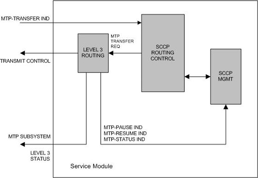
SCCP Routing Control
SCCP routing control receives messages from other nodes in the network via the MTP-Transfer indication.
A load balancing function assigns each LIM to a service module to distribute the SCCP traffic among the available service modules. When a LIM receives an SCCP message that is destined for the EAGLE, it sends the message to the service module assigned to that LIM. If that LIM does not have a service module assigned to it, the LIM discards the SCCP message. If no service modules are equipped or available, the SCCP message is discarded and the LIM transmits a User Part Unavailable MSU to the sending node.
When a LIM receives an SCCP message that is destined for another node, the LIM performs MTP routing and the SCCP message is not sent to the service module. Figure 2-32 shows the message flow for an SCCP message destined for the EAGLE and for an SCCP message destined for another node.
Figure 2-32 SCCP Message Flow through the EAGLE
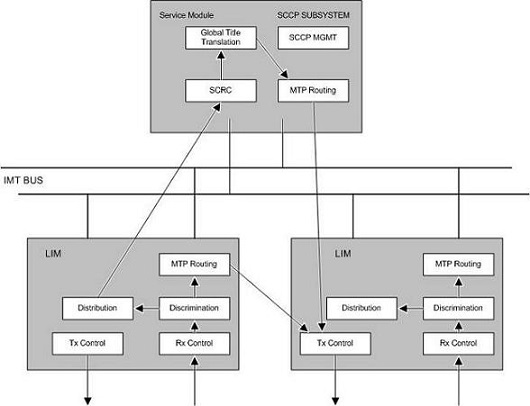
When SCCP receives a message from MTP, it checks the routing indicator in the called party address. There are two types of routing shown by the called party address routing indicator.
- Subsystem (ssn) – This indicates the message is destined for a subsystem at this node. For the EAGLE, the only valid local subsystem is SCCP management (ssn = 1). If the LNP feature is enabled, the EAGLE contains an LNP subsystem which can be numbered from 2 to 255. The LNP subsystem number can be configured with the "Adding a Subsystem Application" procedure in Administration and LNP Feature Activation Guide for ELAP.
- Global Title (gt) – This indicates that global title translation is required. The EAGLE performs the translation, determines the new DPC for the message, and routes the message to that DPC.
Global Title Translation Function
Interaction with the Global Title Translation (GTT) Feature
The SCCP routing function control uses two tables to perform global title translation: the translation type table and the global title translation table. Figure 2-33 shows how these tables are organized.
Figure 2-33 Example of Using Translation Type and Global Title Translation Tables
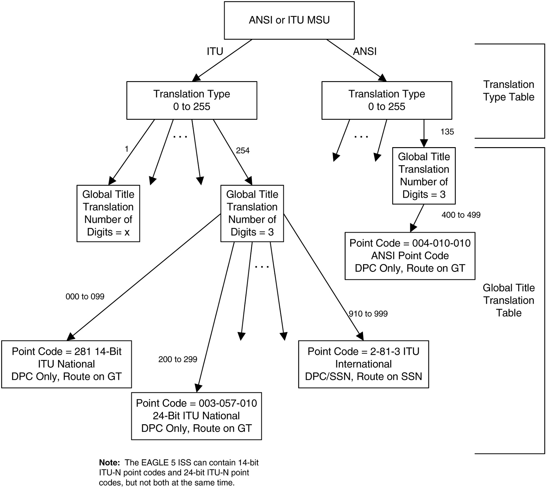
The translation type table is used by SCCP to determine which global title translation table to access. This allows translation tables to be customized to the type of translations that need to be performed, (for example, 6 digit, 800, etc.). The translation block is accessed by using the translation type in the called party address and the network type of the MSU (ANSI or ITU) as an index within the table. Each entry points to the start of a global title translation table.
The translation type table is configured by the
ent-tt command. For more information on
the
ent-tt command, refer to the
Commands Manual.
Each translation type entry in the translation type table contains these fields:
- name of translation type (optional) (8 bytes)
- number of digits (1 byte)
- alias translation type (2 bytes)
- pointer to translation table (4 bytes)
- network type (1 byte)
The global title translation table is used by SCCP to map
a global title address to an SS7 network address so that the SCCP message can
be routed to its destination. The global title translation table is configured
by the
ent-gtt or
chg-gtt commands. For more information
on the
ent-gtt or
chg-gtt commands, refer to
Commands User's Guide.
Each global title translation entry in the global title translation table contains these fields:
- Global title address low value (up to 21 digits) (11 bytes)
- Global title address high value (up to 21 digits) (11 bytes)
- Destination point code (may be an ANSI, ITU national, or ITU international point code) (4 bytes)
- Field that contains either a subsystem number (for route on SSN translation results only) (1 byte) or a new translation type (for new GT translation result only) (1 byte)
- Translation result consisting of one of these
conditions (1 byte):
- Translate on the DPC only, route on GT (subsequent global title translation required)
- Translate on the DPC only, route on SSN
- Translate on the DPC and SSN, route on GT (subsequent global title translation required)
- Translate on the DPC and SSN, route on SSN
- Translate on new GT (subsequent global title translation required)
The translation result determines what data in the message is replaced. The DPC in the routing label is always replaced after the SCCP message is translated. If a point code exists in the called party address, it is also replaced. The subsystem number or the translation type in the called party address can be replaced, but neither have to be replaced. The routing indicator in the called party address can be set to “route on SSN,” or can remain set to “route on GT.” Table 2-29 shows which fields in the MSU are modified for each translation result.
Table 2-29 MSU Fields Modified by Global Title Translation
| Translation Result | Routing Label DPC Replaced | CDPA SSN Replaced | CDPA Routing Indicator Replaced | CDPA Translation Type Replaced | CDPA PC Replaced (if it already exists) |
|---|---|---|---|---|---|
| Translate on DPC only, route on GT | yes | no | no – remains set to route on GT | Can be replaced (See note) | yes |
| Translate on DPC only, route on SSN | yes | no | yes – set to route on SSN | no | yes |
| Translate on DPC and SSN, route on GT | yes | yes | no – remains set to route on GT | no | yes |
| Translate on DPC and SSN, route on SSN | yes | yes | yes – set to route on SSN | no | yes |
| Translate on new GT | yes | no | no – remains set to route on GT | yes | yes |
|
Note: The CDPA translation type can be replaced when translating on the DPC only and routing on GT only if the ANSI/ITU SCCP Conversion feature is enabled. If the ANSI/ITU-China SCCP Conversion feature is not enabled when translating on the DPC only and routing |
|||||
Route on GT
The “Route on GT” translate indicator (subsequent global title translation required) represents the need for a second translation after the initial one.
This need is indicated by the routing bit being set to “route on GT.” In this case, the remote point code table is not checked for status of the subsystem number. Instead, the MSU is sent directly to MTP for routing to the translated point code. If the point code is inaccessible, the MSU is discarded, and a UDTS (unitdata service) message is generated if the return on error option is set.
Interaction with the Enhanced Global Title Translation (EGTT) Feature
The SCCP routing function control uses three tables to perform global title translation: the GTT Selector table, the GTT Set table, and the global title address (GTA) table. The SCCP use the GTT Set table together with the GTT Selector table to determine which GTA table to access. This allows translation tables to be customized with the type of translations that need to be performed.
Figure 2-34 Example of Using GTT Selector, GTT Set, and GTA Tables
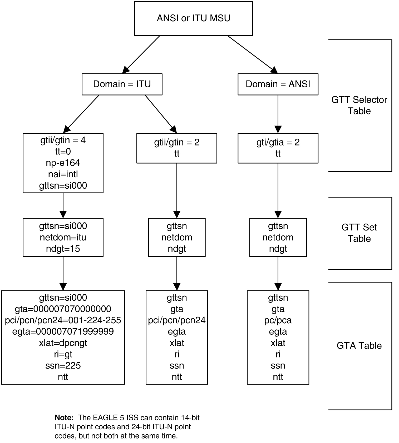
The GTT Set table is configured by the
ent-gttset command; the GTT Selector
table is configured by the
ent-gttsel. For more information on
this command, refer to
Commands User's Guide.
Each GTT Set table contains these fields:
- GTT Set name
- Network domain name
- Number of digits
Each GTT Selector table contains these fields:
- GTT Set name
- The global title indicator (GTI). The GTI defines the
domain as
gtiandgtia(ANSI) with GTI=2gtii(ITU international) with GTI=2 or GTI=4, andgtin(ITU national) with GTI=2 or GTI=4.The global title indicator is made up of the:- name of the global title translation type (TT); and the
- numbering plan (NP) or numbering plan value (NPV) if GTI=4; and the
- nature of address indicator (NAI) or nature
of address indicator value (NAIV) if GTI=4.
Note:
Both the numbering plan and nature of address indicator parameters can be specified by supplying either a mnemonic or an explicit value. At no time may both the mnemonic and the explicit value be specified at the same time for the same parameter.
The GTA table is used by the SCCP to map a global title
address to an SS7 network address so that the SCCP message can be routed to its
destination. The GTA table is configured by the
ent-gta or
chg-gta commands. For more information
on the
ent-gta or
chg-gta commands, refer to
Commands User's Guide.
Each global title address entry in the GTA table contains these fields:
- GTT Set name
- Start of the global title address (up to 21 digits)
- End of the global title address (up to 21 digits)
- Destination point code (may be an ANSI, ITU national, or ITU international point code)
- Translated subsystem number
- Translate indicator
- Cancel Called Global Title indicator
- Routing indicator (translation results)
- Translate on the DPC only, route on GT (subsequent global title translation required)
- Translate on the DPC only, route on SSN
- Translate on the DPC and SSN, route on GT (subsequent global title translation required)
- Translate on the DPC and SSN, route on SSN
- Translate on new GT (subsequent global title translation required)
The translation result determines what data in the message is replaced. The DPC in the routing label is always replaced after the SCCP message is translated. If a point code exists in the called party address, it is also replaced. The subsystem number or the translation type in the called party address can be replaced, but neither have to be replaced. The routing indicator in the called party address can be set to “route on SSN” or can remain set to “route on GT.” Table 2-30 shows which fields in the MSU are modified for each translation result.
Table 2-30 MSU Fields Modified by Enhanced Global Title Translation
| Translation Result | Routing Label DPC Replaced | CDPA SSN Modified | CDPA Routing Indicator Replaced | CDPA Translation Type Replaced | CDPA PC Replaced (if it already exists) | GT Deleted |
|---|---|---|---|---|---|---|
| Translate on DPC only, route on GT | yes | no | no – remains set to route on GT | Can be replaced (See note) | yes | no |
| Translate on DPC only, route on SSN | yes | no | yes – set to route on SSN | no | yes | yes |
| Translate on DPC and SSN, route on GT | yes | yes | no – remains set to route on GT | no | yes | no |
| Translate on DPC and SSN, route on SSN | yes | yes | yes – set to route on SSN | no | yes | yes |
| Translate on new GT | yes | no | no – remains set to route on GT | yes | yes | no |
|
Note: The CDPA translation type can be replaced when translating on the DPC only and routing on GT only if the ANSI/ITU SCCP Conversion feature is enabled. If the ANSI/ITU SCCP Conversion feature is not enabled when translating on the DPC only and routing on GT, the CDPA translation type cannot be replaced. |
||||||
Route on GT
The “Route on GT” translate indicator (subsequent global title translation required) represents the need for a second translation after the initial one.
This need is indicated by routing being set to “route on GT.” In this case, the remote point code table is not checked for status of the subsystem number. Instead, the MSU is sent directly to MTP for routing to the translated point code. If the point code is inaccessible, the MSU is discarded, and a UDTS (unitdata service) message is generated if the return on error option is set.
- If an MSU enters the EAGLE and more information is needed to route the MSU (route-on-gt), the signaling connection control part (SCCP) of the SS7 protocol sends a query to a service database to obtain the information. The EAGLE uses the Enhanced Global Title Translation (EGTT) feature of SCCP to determine which service database to send the query messages to.
- The EGTT feature uses global title information (GTI)
to determine the destination of the MSU. The GTI is contained in the called
party address (CDPA) field of the MSU. For
gti=4, the GTI is made up of the Numbering Plan (NP), Nature of Address Indicator (NAI), and Translation Type (TT) selectors. - The EGTT feature does a Selector Table lookup based on the selector information extracted. If a match is found, then EGTT is performed on the message. If no match is found in the selector table for this entry, then EGTT performs SCRC error handling on the message.
- The EGTT feature decodes the GTA digits and compares
the GTA length with the fixed number of digits specified in the
ndgtparameter of theent-gttselcommand and expected by the translator. If the number of digits received in the CDPA is more than the number of digits specified in thendgtparameter, then the EGTT feature considers the leadingndgtdigits to perform the translation. If the number of digits received in the CDPA is less than the number of digits specified in thendgtparameter, then EGTT discards the message and initiates the SCRC error handling.Note:
If the optional Variable-length Global Title Translation (VGTT) feature is enabled, the EGTT feature allows enhanced global title translation on global title addresses of varying length. For more information about this feature, refer to theVariable-length Global Title Translation Featuresection. - The EGTT feature uses the number of digits received in
the CDPA to perform the Translation Table lookup. If a match is found in the
database, the translation data associated with this entry is used to modify the
message and the resultant message is routed to the next node. If the CDPA GTAI
digits are not found in the database, then standard SCRC error handling is
performed on this message. Refer to
Figure 2-35.
Figure 2-35 EGTT Process
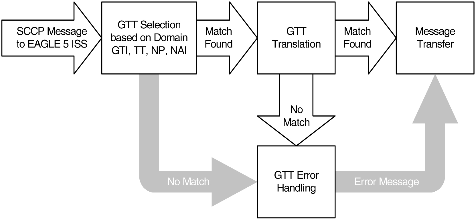
Route on SSN
The “Route on SSN” translate indicator indicates that the point code and SSN is the final destination for the MSU. In this case, the remote point code table is checked to determine the status of the point code and the subsystem number. If the point code or subsystem is unavailable and a backup point code and subsystem is available, the MSU is routed to the backup. Routing to the point codes or subsystems is based upon the data in the remote point code table. There can be up to 31 backup point codes and subsystems assigned to the primary point code and subsystem, thus forming a mated application (MAP) group.
The routing to these backup point codes is based on the
relative cost values assigned to the backup point codes. The lower the relative
cost value is, the higher priority the point code and subsystem has in
determining the routing when the primary point code and subsystem is
unavailable. The relative cost value of the primary point code and subsystem is
defined by the
rc parameter of the
ent-map or
chg-map commands. The relative cost
value of backup point codes and subsystems is defined by the
materc parameter of the
ent-map or
chg-map commands.
There are four routing possibilities for a point code and subsystem number.
- Solitary – there is no backup point code and subsystem for the primary point code and subsystem.
- Dominant – a group of backup point codes and subsystems exists for the primary point code and subsystem. All the point codes and subsystems in this group have different relative cost values, with the primary point code and subsystem having the lowest relative cost value. All traffic is routed to the primary point code and subsystem, if it is available. If the primary point code and subsystem becomes unavailable, the traffic is routed to highest priority backup point code and subsystem that is available. When the primary point code and subsystem becomes available again, the traffic is then routed back to the primary point code and subsystem.
- Load sharing – a group of backup point codes and subsystems is defined for the primary point code and subsystem. All the point codes and subsystems in this group have the same relative cost value. Traffic is shared equally between the point codes and subsystems in this group.
- Combined dominant/load sharing – a group that is a combination of the dominant and load sharing groups. A combined dominant/load shared group is a group that contains a minimum of two RC (relative cost) values that are equal and a minimum of one RC value that is different. The traffic is shared between the point codes with the lowest relative cost values, where the relative cost value is considered the relative cost associated with the point code and subsystem of the global title translation and not the actual lowest relative cost in the MAP set. If these point codes and subsystems become unavailable, the traffic is routed to the other point codes and subsystems in the group and shared between these point codes and subsystems.
For each point code, the user has the option of setting
the
mrc (message reroute on congestion)
parameter. The
mrc parameter, as well as the other
data in the remote point code table, is set with the
ent-map or
chg-map commands. For more information
on the
ent-map or
chg-map commands, refer to
Commands User's Guide.
If the
mrc parameter is set to
no, and the primary point code is
congested, the MSU is discarded, even if a backup point code and subsystem is
available. If the
mrc parameter is set to
yes, and the primary point code is
congested, the MSU is routed to the backup point code and subsystem, if it is
available. The default value for the
mrc parameter is
no if the primary point code is an ITU
national or international point code, and
yes if the primary point code is an
ANSI point code.
SCCP Management
SCCP management is responsible for rerouting signaling traffic when network failures or congestion conditions occur.
MTP network management informs SCCP of any changes in point code routing status. Changes in subsystem status are updated by using the subsystem allowed and subsystem prohibited procedures of SCCP management.
SCCP management updates the status of point codes and
subsystems. Also, SCCP management broadcasts subsystem allowed and prohibited
messages to concerned nodes. The EAGLE supports a broadcast list of up to 96
concerned nodes for each subsystem. This list is configured with the
ent-cspc command. For more information
on the
ent-cspc command, refer to
Commands User's Guide.
For ANSI primary point codes, if the backup point code and subsystem are adjacent when the subsystem becomes prohibited or allowed, these messages are sent to the backup subsystem before routing any messages to it:
- Subsystem prohibited or allowed message
- Subsystem backup routing or subsystem normal routing message
These messages are not required in ITU networks, so if the primary point code is either an ITU national or international point code, these messages are not sent.
Translation Type Mapping
Certain SCCP messages contain a called party address parameter that contains a translation type field. The translation type field indicates the type of global title processing the EAGLE must perform. The values used within any particular network may be different than the standardized values that are defined for internetwork applications.
The translation type mapping feature maps standardized internetwork translation type values to intranetwork translation type values used within any particular network. This feature also maps intranetwork translation type values to standardized internetwork translation type values.
The only SCCP messages that are affected by translation type mapping are UDT and XUDT messages, received or transmitted, whose global title indicator is 0010 (ANSI/ITU) or 0100 (ITU). The translation type will be modified for these messages regardless of whether the destination point code in the MTP routing label is an EAGLE point code and regardless of the SCCP CdPA routing indicator value. Other messages that contain the called party address parameter are not affected. For example, UDTS messages are assumed to be MTP routed and need not be examined. XUDTS messages are either MTP routed or use one translation type value indicating global title to point code translation and should not be mapped.
Translation type mapping is performed on each LIM in the linkset. Incoming translation type mapping is performed on linksets bringing messages into the EAGLE, and is performed before the global title translation function, the gateway screening function. Outgoing translation type mapping is performed on linksets carrying messages out of the EAGLE to other destinations, and is performed after the global title translation function, the gateway screening function.
When outgoing translation type mapping is configured and the MSU must be re-routed due to a changeback or signaling link failure, the re-routed MSU could be double mapped. This is a limitation since re-screening or re-translating (with possible incorrect results) can occur by performing the global title translation and gateway screening functions on the mapped MSU. Figure 2-36 shows an example of a translation type that is double mapped.
Figure 2-36 An Example of Double Translation Type Mapping
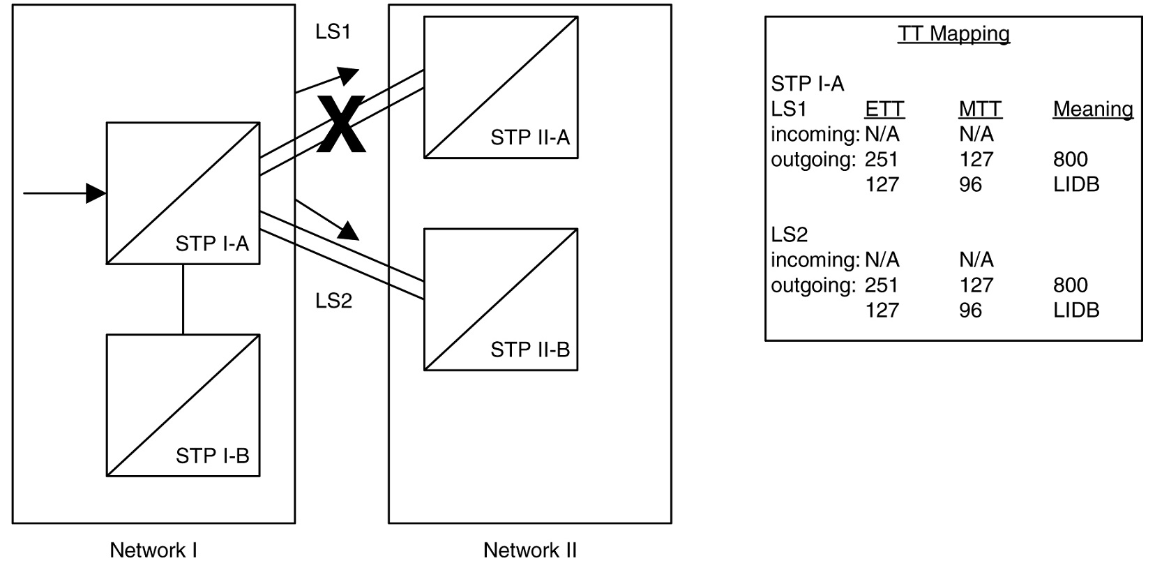
In Figure 2-36, MSUs on the outgoing linkset LS1 containing the existing translation type (ETT) 251 are mapped to translation type 127 (MTT). MSUs on the outgoing linkset LS2 containing the existing translation type 127 are mapped to translation type 96. Linkset LS1 fails and the traffic is re-routed on linkset LS2. Any outgoing traffic that was on linkset LS1 containing the translation type 251 has been changed to translation type 127. When this traffic is re-routed on linkset LS2, the translation type of the messages that was changed to 127 remains 127 and is not changed back to 251. When the messages are sent over linkset LS2, the existing translation type 127 is changed to translation type 96. This is an example of double mapping a translation type. In this example, the messages leaving network 1 on linkset LS1 were mapped to translation type 127, an “800” translation type. Because of double mapping, that translation type was changed to 96, a “LIDB” translation type. These messages can be routed to the wrong subsystem database; or if gateway screening is configured to screen for these messages, these messages could be discarded before they leave network 1, and network 2 would never receive them.
To help prevent this from happening, configure the incoming traffic on the linkset to map the mapped translation type of the outgoing traffic on that linkset (MTT) to the existing translation type for outgoing traffic on that linkset (ETT). In this example, for incoming traffic on linksets LS1 and LS2, map the existing translation type 127 (the mapped translation type for outgoing traffic on these linksets) to the mapped translation type 251 (the existing translation type for outgoing traffic on these linksets). When linkset LS1 fails, the incoming messages on linkset LS2 containing translation type 127, including those that were mapped to 127 on linkset LS1 and are now being rerouted, are now mapped to translation type 251. When these messages become outgoing messages on linkset LS2, those messages containing translation type 251 are mapped to translation type 127 instead of 96. These messages can then continue to be routed to the proper subsystem database. If gateway screening is configured to screen for and discard messages with translation type 96, the rerouted messages are not effected by the results of the translation type mapping.
If the database transport access feature is being used, and the MSU encapsulated by the gateway screening redirect function contains a translation type that must be mapped on an incoming basis, the encapsulated MSU contains the mapped translation type. The translation type of the new MSU is obtained from the gateway screening redirect table.
The EAGLE supports 64 translation type mappings for each linkset. This includes both incoming and outgoing translation type mappings. EAGLE supports translation type mapping entries for 255 linksets. The maximum number of translation type mappings that can be configured in the EAGLE is 16,320.
The translation type mapping information is configured in
the database using the
ent-ttmap,
chg-ttmap,
dlt-ttmap, and
rtrv-ttmap commands.
GTT Configuration
The following procedures describe the steps needed to add, remove, or change global title translation (GTT) data in the database.
Note:
The Global Title Translation (GTT) feature must be purchased before enabling the features with thechg-feat:gtt=on command. If you are not
sure whether you have purchased the GTT feature, contact your Oracle Sales
Representative or Account Representative.
The items configured in this section are:
- Service modules
- Translation type mapping
- Concerned signaling point codes
- Mated applications
- Mated relay nodes.
- GT conversion table entries for the ANSI/ITU SCCP Conversion feature
- Loopsets for the SCCP Loop Detection feature.
- GT modification identifiers for the Advanced GT Modification feature.
To configure the global title translation feature, translation types and global title translations must also be configured. The procedures to configure translation types and global title translations are located in the Global Title Translation (GTT) Configuration section.
The procedures shown in this chapter use a variety of commands. If more information on these commands is needed, refer to Commands User's Guide to find the required information.
There must be SS7 routes to the nodes referenced by the global title translation entities in the database. Perform one of the Adding a Route procedures in Database Administration – SS7 User's Guide to configure these routes.
The following is a brief description of the global title translation entities. These global title translation entities must be configured in the order that they are shown.
- The GTT feature must be turned on with the
chg-feat:gtt=oncommand. Verify this with thertrv-featcommand.Note:
Once the Global Title Translation (GTT) feature is enabled with thechg-featcommand, it cannot be disabled.The GTT feature must be purchased before enabling this feature. If you are not sure whether you have purchased the GTT feature, contact your Oracle Sales Representative or Account Representative.
- A service module must be configured in the database with
the
ent-cardcommand. A service module can be one of these cards: DSM (E5-SM4G/E5-SM8G-B), or SLIC. The DSM card is specified with thetype=dsmandappl=vsccpparameters of theent-cardcommand. The SLIC card is specified withtype=dsm(in the odd numbered card slots) ortype=slic(in the even numbered card slots), andappl=vsccpparameters of theent-cardcommand. Refer to the Adding a Service Module procedure for the required cards. The card configuration can be verified with thertrv-cardcommand. - A translation type must be defined in the database.
Verify this with the
rtrv-ttcommand. If the necessary translation types are not in the database, add them with theent-ttcommand. The translation type is used by theent-gttcommand and defines the length of the global title address.If the Variable-length Global Title Translation (VGTT) feature is being used, it must be enabled with the
chg-feat:vgtt=oncommand. Verify this with thertrv-featcommand. Refer to the Variable-length Global Title Translation Feature section for more information on this feature.Note:
Once the Variable-length Global Title Translation (VGTT) feature is enabled with thechg-featcommand, it cannot be disabled.The VGTT feature must be purchased before enabling this feature. If you are not sure whether you have purchased the VGTT feature, contact your Oracle Sales Representative or Account Representative.
- The translation type can be mapped to another
translation type. This is a function of the translation type mapping feature.
The translation type mapping feature maps standardized internetwork translation
type values to intranetwork translation type values used within any particular
network. This feature also maps intranetwork translation type values to
standardized internetwork translation type values. Enter the
rtrv-ttmapcommand to verify that the necessary translation type mapping information is in the database. Enter the necessary translation type mapping information in the database using theent-ttmapcommand. - The concerned signaling point code broadcast groups must
be defined in the database. These groups define the point codes that receive
subsystem allowed and subsystem prohibited status messages about a particular
global title translation node. These messages are broadcast from SCCP
management. Verify that these groups are in the database with the
rtrv-cspccommand. If these groups are not in the database, add them with theent-cspccommand. - The mated applications must be defined in the database.
The mated applications are the point codes and subsystem numbers of the service
databases along with parameters describing the routing between replicated pairs
of service databases. Verify the mated application information in the database
with the
rtrv-mapcommand. If the necessary mated application information is not in the database, add the necessary information with theent-mapcommand.If the XMAP Table Expansion feature is to be used to increase the number of mated application entries in the mated application table to either 2000 or 3000 entries, the XMAP Table Expansion feature must be enabled with the
enable-ctrl-featcommand. Verify the status of the XMAP Table Expansion feature with thertrv-ctrl-featcommand.The mated applications provide load sharing of the traffic between replicated pairs of service databases. The Flexible GTT Load Sharing feature provides more flexible load sharing capabilities for final global title translations (global title translation containing the routing indicator value SSN) than the mated applications can provide without the Flexible GTT Load Sharing feature enabled. With this feature enabled, MAP sets are provisioned. These MAP sets are assigned to global title translations. Refer to Flexible Final GTT Load Sharing for more information on using the Flexible GTT Load Sharing feature with mated applications.
Load sharing based on the transaction parameters of the message can be performed if the Transaction-Based GTT Load Sharing feature is enabled and turned on. Refer to the Transaction-Based GTT Load Sharing section for more information on using the Transaction-Based GTT Load Sharing feature.
Load sharing based on the weight assigned to an individual entities in a load sharing MAP group can be performed if the Weighted GTT Load Sharing feature is enabled and turned on. Refer to the Weighted GTT Load Sharing section for more information on using the Weighted GTT Load Sharing feature.
- The mated relay node groups can be defined in the
database if the Intermediate GTT Load Sharing feature is to be used. Verify
this with the
rtrv-mrncommand. If the necessary global title translation information is not in the database, add it with theent-mrncommand.The Intermediate GTT Load Sharing (IGTTLS) feature must be enabled with the
enable-ctrl-featandchg-ctrl-featcommands. Verify this with thertrv-ctrl-featcommand. Refer to the Intermediate GTT Load Sharing Feature section for more information on this feature.The Flexible GTT Load Sharing feature provides more flexible load sharing capabilities for intermediate global title translations (global title translation containing the routing indicator value GT) than the Intermediate GTT Load Sharing feature can provide. With this feature enabled, MRN sets are provisioned. These MRN sets are assigned to global title translations. Refer to Flexible Intermediate GTT Load Sharing for more information on using the Flexible GTT Load Sharing feature with mated relay node groups.
Load sharing based on the transaction parameters of the message can be performed if the Transaction-Based GTT Load Sharing feature is enabled and turned on. Refer to the Transaction-Based GTT Load Sharing section for more information on using the Transaction-Based GTT Load Sharing feature.
Load sharing based on the weight assigned to an individual entities in a load sharing MRN group can be performed if the Weighted GTT Load Sharing feature is enabled and turned on. See the Weighted GTT Load Sharing section for more information on using the Weighted GTT Load Sharing feature.
- The global title translation data must be defined in the
database. This data is used to determine the destination of the service
database that needs to queried for additional routing information. Verify this
with the
rtrv-gttcommand. If the necessary global title translation information is not in the database, add it with theent-gttcommand.If the Advanced GT Modification feature is being used, it must be enabled with theenable-ctrl-featcommand. Verify this with thertrv-ctrl-featcommand. Refer to the Advanced GT Modification Feature section for more information on this feature.Note:
Once the Advanced GT Modification feature is enabled, it cannot be disabled.If the XGTT Table Expansion feature is to be used to increase the number of mated application entries in the mated application table to either 400,000 or 1,000,000 entries, the XGTT Table Expansion feature must be enabled with the
enable-ctrl-featcommand. Verify the status of the XGTT Table Expansion feature with thertrv-ctrl-featcommand.The ANSI/ITU SCCP Conversion feature provides a means to perform SCCP conversion between ANSI MSUs and ITU MSUs. To perform this conversion, the ANSI/ITU SCCP Conversion feature must be enabled with the
enable-ctrl-featcommand, and turned on with thechg-ctrl-featcommand. Verify the status of the ANSI/ITU SCCP Conversion feature with thertrv-ctrl-featcommand. Entries must be also configured in the GT conversion table with theent-gtcnvcommand. The content of the GT conversion table can be verified with thertrv-gtcnvcommand.Decimal digits (0-9) or hexadecimal digits (0-9, a-f, A-F) can be specified for these items that are assigned to the global title translation entry.- The global title address (
gtaandegta) values - Entries in the GT conversion table
- The prefix (
npds) and suffix (nsds) values in the GTMOD identifier that is assigned to the global title translation entry.
Hexadecimal digits can be specified only if the Hex Digit Support for GTT feature is enabled. Verify the status of the Hex Digit Support for GTT feature with the
rtrv-ctrl-featcommand. Refer to the Hex Digit Support for GTT section for more information on this feature.The SCCP Loop Detection feature provides a method for detecting SCCP looping. With this feature enabled, loopsets are provisioned. These loopsets are assigned to Global Title Translations. See the SCCP Loop Detection section for more information on using the SCCP Loop Detection feature with Global Title Translations.
- The global title address (
EGTT Configuration
- GTT sets
- GTT selectors
- Global title address information
- GTT action sets
- GTT action per-path measurements
The procedures to configure these items are located in the Enhanced Global Title Translation (EGTT) Configuration section.
The translation type (ent-/dlt-/rtrv-tt) and the GTT (ent-/dlt-/chg-/rtrv-gtt)
commands can be executed when the EGTT feature is turned on, but will only
produce CDGTA GTT sets and CDGTA GTT selectors.
The following is a brief description of the enhanced global title translation entities. These entities must be configured in the order that they are shown.
- The Enhanced Global Title Translation (EGTT) feature
must be turned on with the
chg-feat:egtt=oncommand. The Global Title Translation (GTT) must be on before the EGTT feature can be turned on. Verify this with thertrv-featcommand.Note:
Once the Enhanced Global Title Translation (EGTT) feature is turned on with thechg-featcommand, it cannot be turned off.The EGTT feature must be purchased before turning on the feature. If you are not sure whether you have purchased the EGTT feature, contact your Sales Representative or Account Representative.
- A service module must be configured in the database with
the
ent-cardcommand. A service module can be either a DSM or SLIC card. The DSM card is specified with thetype=dsmandappl=vsccpparameters of theent-cardcommand. The SLIC card is specified withtype=dsm(in the odd numbered card slots) ortype=slic(in the even numbered card slots), andappl=vsccpparameters of theent-cardcommand.. Refer to the Adding a Service Module procedure for the required cards. The card configuration can be verified with thertrv-cardcommand. - A global title translation (GTT) set must be defined in
the database. Verify this with the
rtrv-gttsetcommand. If the necessary GTT set is not in the database, add it with theent-gttsetcommand.If the Variable-length Global Title Translation (VGTT) feature is being used, it must be turned on with the
chg-feat:vgtt=oncommand. Verify this with thertrv-featcommand. Refer to the Variable-length Global Title Translation Feature section for more information on this feature.Note:
Once the Variable-length Global Title Translation (VGTT) feature is turned on with thechg-featcommand, it cannot be turned off.The VGTT feature must be purchased before turning it on. If you are not sure whether you have purchased the VGTT feature, contact your Oracle Sales Representative or Account Representative.
- A translation type must be defined in the database.
Verify this with the
rtrv-gttselcommand. If the necessary translation types are not in the database, add them with theent-gttselcommand. The translation type is used by theent-gtacommand and defines the length of the global title address. - The translation type can be mapped to another
translation type. This is a function of the translation type mapping feature.
The translation type mapping feature maps standardized internetwork translation
type values to intranetwork translation type values used within any particular
network. This feature also maps intranetwork translation type values to
standardized internetwork translation type values. Enter the
rtrv-ttmapcommand to verify that the necessary translation type mapping information is in the database. Enter the necessary translation type mapping information in the database using theent-ttmapcommand. - The concerned signaling point code broadcast groups must
be defined in the database. These groups define the point codes that receive
subsystem allowed and subsystem prohibited status messages about a particular
global title translation node. These messages are broadcast from SCCP
management. Verify that these groups are in the database with the
rtrv-cspccommand. If these groups are not in the database, add them with theent-cspccommand. - The mated applications must be defined in the database.
The mated applications are the point codes and subsystem numbers of the service
databases along with parameters describing the routing between replicated pairs
of service databases. Verify the mated application information in the database
with the
rtrv-mapcommand. If the necessary mated application information is not in the database, add the necessary information with theent-mapcommand.If the XMAP Table Expansion feature is to be used to increase the number of mated application entries in the mated application table to either 2000 or 3000 entries, the XMAP Table Expansion feature must be enabled with the
enable-ctrl-featcommand. Verify the status of the XMAP Table Expansion feature with thertrv-ctrl-featcommand.The mated applications provide load sharing of the traffic between replicated pairs of service databases. The Flexible GTT Load Sharing feature provides more flexible load sharing capabilities for final global title translations (global title translation containing the routing indicator value SSN) than the mated applications can provide without the Flexible GTT Load Sharing feature enabled. With this feature enabled, MAP sets are provisioned. These MAP sets are assigned to global title translations. Refer to Flexible Final GTT Load Sharing for more information on using the Flexible GTT Load Sharing feature with mated applications.
Load sharing based on the transaction parameters of the message can be performed if the Transaction-Based GTT Load Sharing feature is enabled and turned on. Refer to the Transaction-Based GTT Load Sharing section for more information on using the Transaction-Based GTT Load Sharing feature.
- The mated relay node groups can be defined in the
database if the Intermediate GTT Load Sharing feature is to be used. Verify
this with the
rtrv-mrncommand. If the necessary global title translation information is not in the database, add it with theent-mrncommand.The Intermediate GTT Load Sharing (IGTTLS) feature must be enabled with the
enable-ctrl-featandchg-ctrl-featcommands. Verify this with thertrv-ctrl-featcommand. Refer to the Intermediate GTT Load Sharing Feature section for more information on this feature.The Flexible GTT Load Sharing feature provides more flexible load sharing capabilities for intermediate global title translations (global title translation containing the routing indicator value GT) than the Intermediate GTT Load Sharing feature can provide. With this feature enabled, MRN sets are provisioned. These MRN sets are assigned to global title translations. Refer to Flexible Intermediate GTT Load Sharing for more information on using the Flexible GTT Load Sharing feature with mated relay node groups.
Load sharing based on the transaction parameters of the message can be performed if the Transaction-Based GTT Load Sharing feature is enabled and turned on. Refer to the Transaction-Based GTT Load Sharing section for more information on using the Transaction-Based GTT Load Sharing feature.
Load sharing based on the weight assigned to an individual entities in a load sharing MRN group can be performed if the Weighted GTT Load Sharing feature is enabled and turned on. Refer to the Weighted GTT Load Sharing section for more information on using the Weighted GTT Load Sharing feature.
- The global title address data must be defined in the
database. This data is used to determine the destination of the service
database that needs to be queried for additional routing information. Verify
this with the
rtrv-gtacommand. If the necessary global title address information is not in the database, add it with theent-gtacommand.If the Advanced GT Modification feature is being used, it must be enabled with theenable-ctrl-featcommand. Verify this with thertrv-ctrl-featcommand. Refer to the Advanced GT Modification Feature section for more information on this feature.Note:
Once the Advanced GT Modification feature is enabled, it cannot be disabled.The XGTT Table Expansion feature is used to increase the number of entries in the GTT table to either 400,000 or 1,000,000 entries, the XGTT Table Expansion feature must be enabled with the
enable-ctrl-featcommand. Verify the status of the XGTT Table Expansion feature with thertrv-ctrl-featcommand.The ANSI/ITU SCCP Conversion feature provides a means to perform SCCP conversion between ANSI MSUs and ITU MSUs. To perform this conversion, the ANSI/ITU SCCP Conversion feature must be enabled with the
enable-ctrl-featcommand, and turned on with thechg-ctrl-featcommand. Verify the status of the ANSI/ITU SCCP Conversion feature with thertrv-ctrl-featcommand. Entries must be also configured in the GT conversion table with theent-gtcnvcommand. The content of the GT conversion table can be verified with thertrv-gtcnvcommand.Decimal digits (0-9) or hexadecimal digits (0-9, a-f, A-F) can be specified for these items that are assigned to the global title address entry.- The global title address (
gtaandegta) values - Entries in the GT conversion table
- The prefix (
npds) and suffix (nsds) values in the GTMOD identifier that is assigned to the global title address entry.
Hexadecimal digits can be specified only if the Hex Digit Support for GTT feature is enabled. Verify the status of the Hex Digit Support for GTT feature with the
rtrv-ctrl-featcommand. Refer to the Hex Digit Support for GTT section for more information on this feature.The SCCP Loop Detection feature provides a method for detecting SCCP looping. With this feature enabled, loopsets are provisioned. These loopsets are assigned to Global Title Translations. Refer to the SCCP Loop Detection section for more information on using the SCCP Loop Detection feature with Global Title Translations.
- The global title address (
- A set of these actions, discard, UDTS, duplicate, TCAP error, forward, and services (SRVC) for GPORT, GFLEX and SMSMR can be assigned to the global title address entry. These actions are contained in a GTT action set. A GTT action set name identifies each set of these actions and this name is assigned to the global title address entry. The actions in the action set are performed on the MSU when global title translation finishes processing the MSU. Refer to the GTT Actions section for more information on using GTT actions with the global title address entries.
- The GTT Action per-path measurements provides measurement counts for the GTT actions that are applied to messages that match a pre-defined combination of CgPA GTA, CdPA GTA, and Opcode values, called a path. The combination of these values are provisioned in the GTT Path table. Refer to the GTT Actions section for more information on using GTT Action per-path measurements.
Adding a Service Module
This procedure is used to add a service module to
support the Global Title Translation or Enhanced Global Title Translation
feature to the database using the
ent-card command.
- E5-SM8G-B
- SLIC
The card that is used as a service module depends on the
GTT related features that are being used and the features that will enabled
after this procedure is performed. The features or feature combinations shown
in
Table 2-31
show the type of card that must be installed in the EAGLE to meet the minimum
EAGLE performance requirements. The features that are currently being used by
the EAGLE are shown in the
rtrv-feat or
rtrv-ctrl-feat command outputs.
Table 2-31 Service Module and Feature Combinations
| Card | Features |
|---|---|
|
E5-SM8G SLIC |
Any of these features:
or GTT and EGTT (if the Enhanced Global Title Translation feature is on) in combination with at least 2 of these features:
|
The E5-SM8G-B can be inserted only in the odd numbered card slots of the control or the extension shelf. Slots 09 and 10 of each shelf contains the HIPR2 card, thus the E5-SM8G-B cannot be inserted in slot 09 and 10. The E5-SM8G-B can be inserted in the control shelf, but only in slots 01, 03, 05, 07 and 11. The E5-SM8G-B occupies two card slots, so the even numbered card slot adjacent to the odd numbered slot where the E5-SM8G-B has been inserted must be empty, as shown in Table 2-32. The E5-SM8G-B is connected to the network through the odd numbered card slot connector. The E5-SM8G-B requires two HIPR2 cards in the shelf where it is installed.
The SLIC can be inserted only in the odd numbered card slots if it is
provisioned with the
type=dsm parameter of the
ent-card command. The SLIC can be
inserted in odd or even numbered card slots if it is provisioned with the
type=slic parameter of the
ent-card command.
Table 2-32 Card Locations
| Location of the E5-SM8G-B | Empty Card Location |
|---|---|
| Slot 11 | Slot 12 |
| Slot 13 | Slot 14 |
| Slot 15 | Slot 16 |
| Slot 17 | Slot 18 |
The
ent-card command uses these
parameters:
:loc – The location of the card being added to the database.
:type – The type of
card being added to the database. The value of this parameter is
dsm or
slic.
:appl – The
application software that is assigned to the card. The value of this parameter
is
vsccp.
:data – The data type
of the card when running the EPAP Data Split feature and the Dual ExAP
Configuration feature. The value of this parameter is
dn or
imsi for the EPAP Data Split feature
and
ELAP,
EPAP or
GTT for the Dual ExAP Configuration
feature.
The shelf to which the card is to be added must already
be in the database. This can be verified with the
rtrv-shlf command. If the shelf is not
in the database, perform the "Adding a Shelf" procedure in
Database Administration – System Management User's
Guide.
The card cannot be added to the database if the specified card location already has a card assigned to it.
Note:
If you want to add an E5-SM8G-B or SLIC card as the service module, verify the temperature threshold settings for the appropriate card by performing the "Changing the High-Capacity Card Temperature Alarm Thresholds" procedure in Database Administration - SS7 User's Guide. The E5-SM8G-B card also requires a fan tray.Figure 2-37 Add a Service Module - Sheet 1 of 4
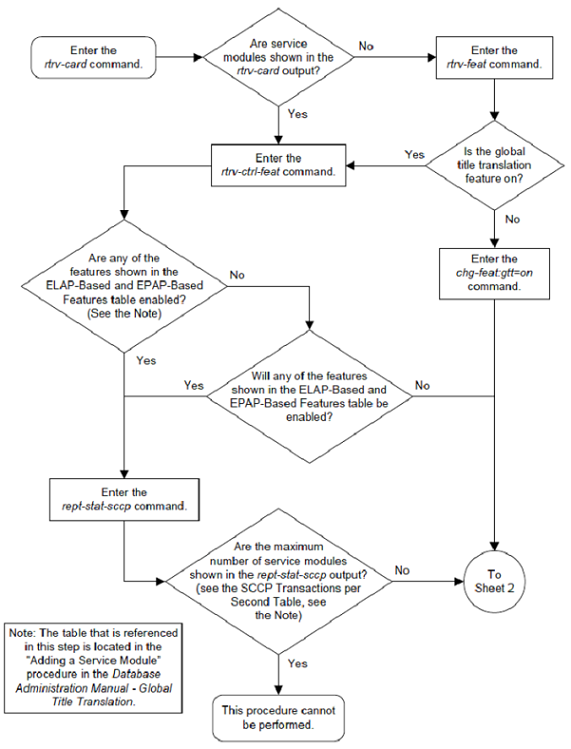
Figure 2-38 Add a Service Module - Sheet 2 of 4
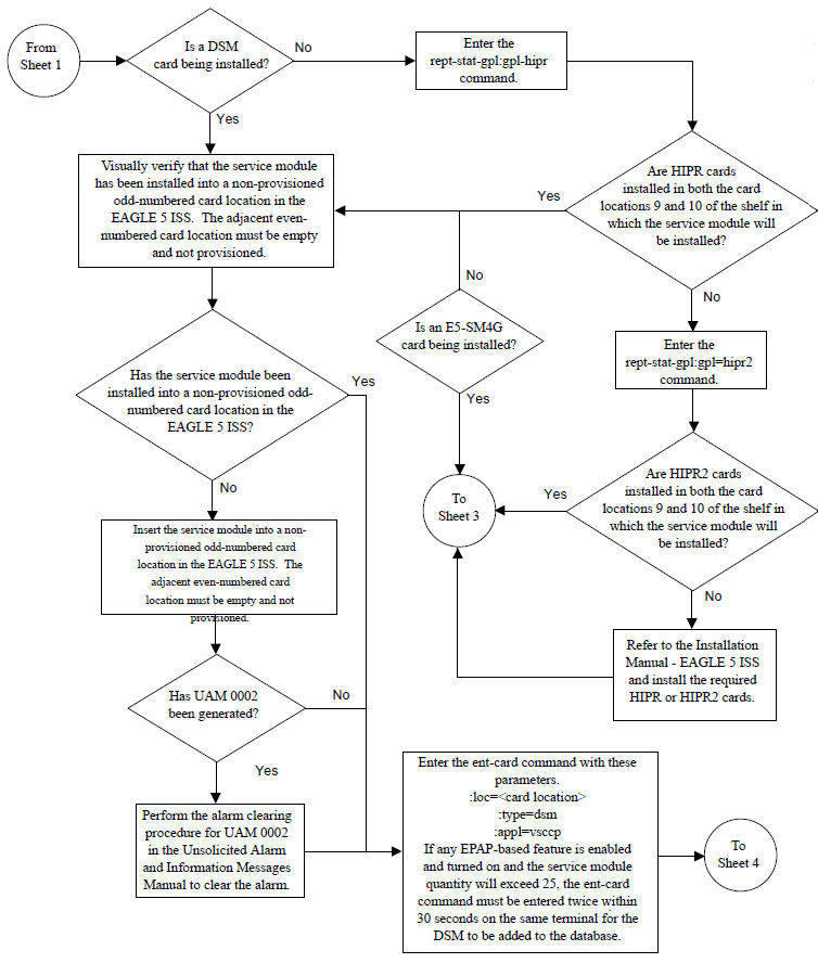
Figure 2-39 Add a Service Module - Sheet 3 of 4
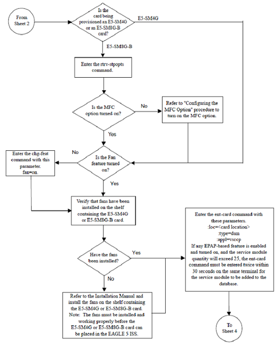
Figure 2-40 Add a Service Module - Sheet 4 of 4
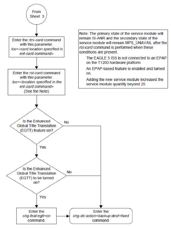
Removing a Service Module
This procedure is used to remove a service module, used
by global title translation, from the database using the
dlt-card command. The card cannot be
removed if it does not exist in the database.
Caution:
If the service module is the last service module in service, removing this card from the database will cause global title translation traffic to be lost.The examples in this procedure are used to remove the service module in card location 1204.
Figure 2-41 Remove a Service Module
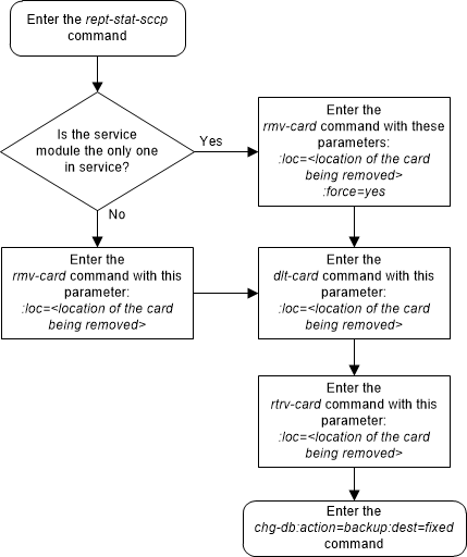
Adding a Mapped SS7 Message Translation Type
This procedure is used to add a mapped SS7 message
translation type to the database. The mapped translation type is added to the
database using the
ent-ttmap command and is assigned to an
ANSI SS7 linkset.
The
ent-ttmap command uses these
parameters.
:lsn – the name of the
linkset.
:io – is translation type
mapping to be performed on SS7 messages received in the linkset (incoming
linkset) or on SS7 messages sent on the linkset (outgoing linkset).
:ett – the translation
type contained in the SS7 message before that translation type is mapped.
:mtt – the translation
type that the value of the
ett parameter is mapped to.
The examples in this procedure are used to map the SS7
message translation type
250 to the translation type
001 for any incoming messages on
linkset
lsn01.
Canceling the
RTRV-LS Command
Because the
rtrv-ls command used in this procedure
can output information for a long period of time, the
rtrv-ls command can be canceled and the
output to the terminal stopped. There are three ways that the
rtrv-ls command can be canceled.
-
Press the
F9function key on the keyboard at the terminal where thertrv-lscommand was entered. -
Enter the
canc-cmdwithout thetrmparameter at the terminal where thertrv-lscommand was entered. -
Enter the
canc-cmd:trm=<xx>, where<xx>is the terminal where thertrv-lscommand was entered, from another terminal other that the terminal where thertrv-lscommand was entered. To enter thecanc-cmd:trm=<xx>command, the terminal must allow Security Administration commands to be entered from it and the user must be allowed to enter Security Administration commands. The terminal’s permissions can be verified with thertrv-secu-trmcommand. The user’s permissions can be verified with thertrv-userorrtrv-secu-usercommands.
For more information about the
canc-cmd command, go to
Commands User's Guide.
Figure 2-42 Add a Mapped SS7 Message Translation Type
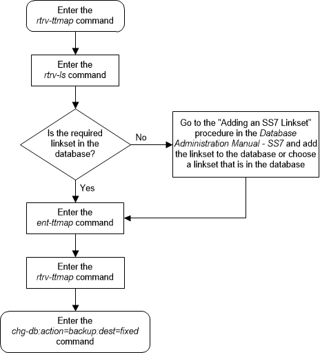
Removing a Mapped SS7 Message Translation Type
This procedure is used to remove a mapped SS7 message
translation type from the database using the
dlt-ttmap command.
The
dlt-ttmap command uses these
parameters.
:lsn – the name of the
linkset.
:io – is translation type
mapping to be performed on SS7 messages received in the linkset (incoming
linkset) or on SS7 messages sent on the linkset (outgoing linkset).
:ett – the translation
type contained in the SS7 message before that translation type is mapped.
The examples in this procedure are used to remove the
translation type
016 for any outgoing messages on
linkset
nc001.
Figure 2-43 Remove a Mapped SS7 Message Translation Type
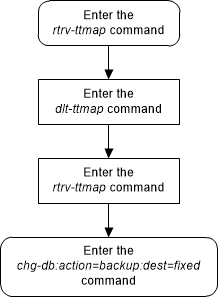
Changing a Mapped SS7 Message Translation Type
This procedure is used to change a mapped SS7 message
translation type in the database using the
chg-ttmap command.
The
chg-ttmap command uses these
parameters.
:lsn – the name of the
linkset.
:io – is translation type
mapping to be performed on SS7 messages received in the linkset (incoming
linkset) or on SS7 messages sent on the linkset (outgoing linkset).
:ett – the translation
type contained in the SS7 message before that translation type is mapped.
:mtt – the translation
type that the value of the
ett parameter is mapped to.
Only the mapped translation type (mtt) can be changed with this procedure. To change the
lsn,
io, or
ett values, the mapped translation type
entry has to be removed from the database using the
Removing a Mapped SS7 Message Translation Type
procedure, then re-entered with the new
lsn,
io, or
ett values using the
Adding a Mapped SS7 Message Translation Type
procedure.
The examples in this procedure are used to change the
mapped translation type
250, being mapped for translation type
001 for incoming messages on linkset
lsn01 to mapped translation type
255.
Figure 2-44 Change a Mapped SS7 Message Translation Type
Adding a Concerned Signaling Point Code
This procedure is used to add a concerned signaling point
code (CSPC) group to the database using the
ent-cspc command.
The
ent-cspc command uses these parameters.
:grp – The name of the
concerned signaling point code group that contains the point codes that should
be notified of the subsystem status.
:pc/pca/pci/pcn/pcn24 –
The point code of the signaling point that is to be in the concerned signaling
point code group, either an ANSI point code (pc/pca), ITU-I or ITU-I spare point code (pci), a 14-bit ITU-N or 14-bit ITU-N spare point code
(pcn), or a 24-bit ITU-N (pcn24) point code.
Note:
Refer to Chapter 2, Configuring Destination Tables in Database Administration - SS7 User's Guide for a definition of the point code types that are used on the EAGLE and for a definition of the different formats that can be used for ITU national point codes.Note:
The EAGLE can contain 14-bit ITU-N point codes or 24-bit ITU-N point codes, but not both at the same time.The examples in this procedure are used to add the concerned signaling point code (CSPC) groups shown in Table 2-37.
Table 2-37 Concerned Signaling Point Code Configuration Table
| CSPC Broadcast Group Name | Concerned Signaling Point Code |
|---|---|
| grp05 | 002-002-002 |
| 008-008-008 | |
| grp10 | 008-008-008 |
| 009-009-009 | |
| grp15 | 002-002-002 |
| 009-009-009 |
The CSPC cannot be in the database for the indicated group.
The point code must exist in the routing table and cannot
already exist in the specified group. Verify that the point code is in the
routing table by entering the
rtrv-rte command with the point code.
If the point code is an ANSI point code, it must be a full point code. The
route must contain a minimum of one active signaling link.
The word “none” cannot be used to name a CSPC group.
The database can contain a maximum of 2550 CSPC groups. Each CSPC group can contain a maximum of 96 concerned signaling point codes.
The mated point codes in the mated application table will not automatically receive CSPC broadcasts unless each mated point code is contained in a CSPC group. A mated application group can contain up to 32 entries, a primary point code and up to 31 mated point codes. Each mated point code in a mated application group can be assigned to a different CSPC group.
The first point code entered for a CSPC group defines the
network type for the CSPC group. If the first point code entered for a
particular CSPC group is an ANSI point code (pc
or
pca), then that CSPC group is an ANSI
CSPC group and only ANSI point codes can be added to it. If the first point
code in the CSPC group is either an ITU international or ITU international
spare point code (pci), then the CSPC group is
an ITU international CSPC group and only ITU international or ITU international
spare point codes can be added to it. If the first point code in the CSPC group
is either a 14-bit ITU national or 14-bit ITU national spare point code
(pcn), then the CSPC group is an ITU national
CSPC group and only 14-bit ITU national or 14-bit ITU national spare point
codes can be added to it. If the first point code in the CSPC group is a 24-bit
ITU national point code (pcn24), then the CSPC
group is an ITU national CSPC group and only 24-bit ITU national point codes
can be added to it.
If the ANSI/ITU SCCP Conversion feature is enabled, CSPC
groups can contain ANSI point codes (pc/pca),
ITU-I or ITU-I spare point codes (pci), and
either 14-bit ITU-N or 14-bit ITU-N spare point codes (pcn), or 24-bit ITU-N (pcn24) point codes. A CSPC group cannot contain both
14-bit and 24-bit ITU-N point codes. The status of the ANSI/ITU SCCP Conversion
feature can be verified with the
rtrv-ctrl-feat command.
When the
ent-cspc command is entered with a CSPC
group name and a point code and the CSPC group name does not exist, the command
will be rejected. If the group name does not exist, and a point code is not
specified, a new group will be created.
Figure 2-45 Add a Concerned Signaling Point Code - Sheet 1 of 4
Figure 2-46 Add a Concerned Signaling Point Code - Sheet 2 of 4
Figure 2-47 Add a Concerned Signaling Point Code - Sheet 3 of 4
Figure 2-48 Add a Concerned Signaling Point Code - Sheet 4 of 4
Removing a Concerned Signaling Point Code
This procedure is used to remove a concerned signaling
point code (CSPC) group from the database using the
dlt-cspc command.
The
dlt-cspc command uses these parameters.
:grp – The name of the
concerned signaling point code group that contains the point codes that should
be notified of the subsystem status.
:pc/pca/pci/pcn/pcn24 –
The point code of the signaling point that is to be in the concerned signaling
point code group, either an ANSI point code (pc/pca), ITU-I or ITU-I spare point code (pci), a 14-bit ITU-N or 14-bit ITU-N spare point code
(pcn), or a 24-bit ITU-N (pcn24) point code.
Note:
Refer to Chapter 2, Configuring Destination Tables in Database Administration - SS7 User's Guide for a definition of the point code types that are used on the EAGLE and for a definition of the different formats that can be used for ITU national point codes.:all – Confirms that all
entries for a particular concerned signaling point code group are to be
removed.
The examples in this procedure are used to remove the
concerned signaling point code
008-008-008 from the CSPC group
grp10 from the database.
The CSPC must be in the database for the indicated group.
Figure 2-49 Remove a Concerned Signaling Point Code - Sheet 1 of 3
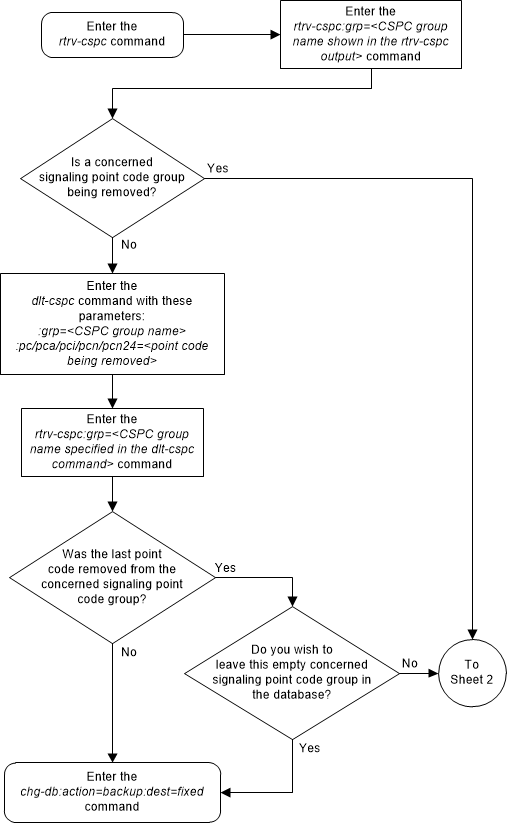
Figure 2-50 Remove a Concerned Signaling Point Code - Sheet 2 of 3
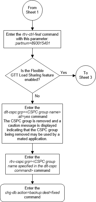
Figure 2-51 Remove a Concerned Signaling Point Code - Sheet 3 of 3
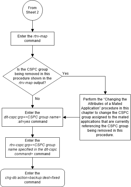
Provisioning a Solitary Mated Application
This procedure is used to provision a solitary mated
application in the database using the
ent-map command. A solitary mated
application contains only one entry. The
ent-map command use these parameters to
provision a solitary mated application.
:pc/pca/pci/pcn/pcn24 –
The point code of the signaling point that is to receive the message.
Note:
The point codes can be either an ANSI point code (pc/pca),
ITU-I or ITU-I spare point code (pci), a
14-bit ITU-N or 14-bit ITU-N spare point code (pcn), or a 24-bit ITU-N (pcn24) point code.
Note:
Refer to Chapter 2, Configuring Destination Tables in the Database Administration - SS7 User's Guide for a definition of the point code types that are used on the EAGLE and for a definition of the different formats that can be used for ITU national point codes.:ssn – Subsystem number –
the subsystem address of the point code that is to receive the message. The
value for this parameter is 2 to 255.
:grp – The name of the
concerned signaling point code (CSPC) group that contains the point codes that
should be notified of the subsystem status. This parameter applies to both
RPCs/SSNs. The value for this parameter is shown in the
rtrv-cspc output. If the desired value
is not shown in the
rtrv-cspc output, perform the
Adding a Concerned Signaling Point Code
procedure to add the desired group. If this parameter is not specified, then a
CSPC group name is not specified for the mated application.
:sso – Subsystem Status
Option – defines whether the subsystem status option is on or off. This
parameter allows the user the option to have the specified subsystem marked as
prohibited even though an MTP-RESUME message has been received by the
indicating that the specified point code is allowed. The
sso parameter cannot be specified if
the
pc/pca/pci/pcn/pcn24 value is the
EAGLE’s true point code, shown in the
rtrv-sid output. The value for this
parameter is
on or
off. The default value is
off.
:mapset – The MAP set ID
that the mated applications are assigned to. This parameter can be specified
only if the Flexible GTT Load Sharing feature is enabled. This parameter must
be specified if the Flexible GTT Load Sharing feature is enabled. If the
Flexible GTT Load Sharing feature is enabled, the point code and subsystem
specified for the global title translation must be assigned to the MAP set
specified by this parameter. The status of the Flexible GTT Load Sharing
feature is shown in the
rtrv-ctrl-feat output. To enable the
Flexible GTT Load Sharing feature, perform the
Activating the Flexible GTT Load Sharing Feature
procedure.
The
mapset parameter has three values.
dflt– to assign the MAP to the default MAP set.new– to assign the mated application to a new MAP set.- The specific number of an existing MAP set if you are
assigning the mated application to an existing MAP set. This value can be
specified only with the
chg-mapcommand.
Refer to the Provisioning a MAP Set section for information on provisioning MAP sets.
:mrnset – The MRN set
ID that is being assigned to the mated application. This is the MRN set from
which alternate routing indicator searches are performed.
:mrnpc/mrnpca/mrnpci/mrnpcn/mrnpcn24 – The point code
assigned to the
mrnset that is being assigned to the
MAP set.
The current values of the
mrnset and
:mrnpc/mrnpca/mrnpci/mrnpcn/mrnpcn24
parameters are shown in the
rtrv-map output only if the Flexible
GTT Load Sharing and the GTT Load Sharing with Alternate Routing Indicator
features are enabled.
The new values for the
mrnset and
mrnpc/mrnpca/mrnpci/mrnpcn/mrnpcn24
parameters must be shown in the
rtrv-mrn output.
The network type of the
pc/pca/pci/pcn/pcn24 and
mrnpc/mrnpca/mrnpci/mrnpcn/mrnpcn24
parameter values must be compatible, as shown in
Table 2-38.
Table 2-38 MAP and MRN Point Code Parameter Combinations
| MAP Point Code Parameter | MRN Point Code Parameter |
|---|---|
| pc/pca | mrnpc/mrnpca |
| pci or pcn (See Notes 1 and 2) | mrnpci or mrnpcn (See Notes 1 and 2) |
| pcn24 | mrnpcn24 |
Note:
- 1. If the network type
of the MAP point code parameter is ITU-I (
pci), the network type of the MRN point code parameter can be either ITU-I (mappci) or ITU-N (mappcn). - 2. If the network type
of the MAP point code parameter is ITU-N (
pcn), the network type of the MRN point code parameter can be either ITU-I (mappci) or ITU-N (mappcn).
:mrc – Message routing
under congestion – specifies whether Class 0 messages are routed during
congestion conditions. The values for this parameter are
yes and
no. This parameter can be specified
for any type of mated application, but this parameter affects only the traffic
for a dominant mated application. The default value for ANSI, ITU-I, and ITU-N
solitary mated applications is
yes. The default value for ITU-N24
solitary mated applications is
no.
:srm – Subsystem
routing messages – defines whether subsystem routing messages (SBR, SNR) are
transmitted between the mated applications. The values for this parameter are
yes and
no. The
srm=yes parameter can be specified
only for ANSI mated applications. This parameter affects traffic only on
dominant and combined dominant/load shared mated applications. The default
value for ANSI solitary mated applications is
yes. The default value for ITU
solitary mated applications is
no.
The
ent-map command also contains other
parameters that can be used to provision mated applications, but cannot be used
to provision a solitary mated applications. These parameters are:
mpc/mpca/mpci/mpcn/mpcn24,
mssn,
rc,
materc. If you wish to use these
parameters to provision mated applications, perform one of these procedures.
- Provisioning a Dominant Mated Application
- Provisioning a Load Shared Mated Application
- Provisioning a Combined Dominant/Load Shared Mated Application
The
rc parameter can be specified for a
solitary mated application, but since a solitary mated application contains
only one entry, the
rc parameter does not need to be
specified. If the
rc parameter is not specified, the
rc value is set to 10.
If the Weighted GTT Load Sharing feature is enabled,
shown by the columns
WT,
%WT, and
THR in the
rtrv-map output, the parameters
wt,
mwt, and
thr cannot be specified for a solitary
mated application. If you wish to use these parameters to provision a mated
application, perform one of these procedures:
- Provisioning a Load Shared Mated Application
- Provisioning a Combined Dominant/Load Shared Mated Application
If the Flexible GTT Load Sharing feature is not enabled, the point code and subsystem number combination can be in the database only once. If the Flexible GTT Load Sharing feature is enabled, the point code and subsystem number combination can be in multiple MAP sets, but can be in the default MAP set only once. Refer to the Provisioning a MAP Set section for information on provisioning MAP sets.
The point codes specified in the
ent-map command (pc/pca,
pci,
pcn, or
pcn24) must be either a full point code
in the routing point code table or the EAGLE’s true point code. Cluster point
codes or network routing point codes cannot be specified with this command. The
rtrv-rte command can be used to verify
the point codes in the routing table. The point codes in the routing table are
shown in the
DPCA,
DPCI,
DPCN, or
DPCN24 fields of the
rtrv-rte command output. The EAGLE’s
true point code is shown in the
PCA,
PCI,
PCN, or
PCN24 fields of the
rtrv-sid command output.
A solitary mated application can be provisioned with a point code that is assigned to other mated applications as long as the SSN is not assigned to other mated applications. A point code can be assigned to maximum of 12 different SSNs.
If the EAGLE’s true point code is specified in the mated application and the Flexible GTT Load Sharing feature is enabled, the mated application containing the EAGLE’s true point code can be assigned only to the default MAP set.
A mated application containing the LNP subsystem can contain only the EAGLE's ANSI true point code. The LNP feature must be enabled for a quantity greater than zero.
A mated application containing the INP subsystem can contain only the EAGLE’s true14-bit ITU-N point code, 14-bit ITU-N spare point code, or 24-bit ITU-N point code. The INP or ANSI-41 INP Query feature must be enabled and turned on. The EAGLE can contain either 14-bit ITU-N point codes (spare or non-spare point codes) or 24-bit ITU-N point codes. Both types of point codes cannot be present on the EAGLE at the same time.
A mated application containing the EIR subsystem can contain only the EAGLE’s true ITU-I point code, ITU-I spare point code, 14-bit ITU-N point code, 14-bit ITU-N spare point code, or 24-bit ITU-N point code. The EIR feature must be enabled and turned on. The EAGLE can contain either 14-bit ITU-N point codes (spare or non-spare point codes) or 24-bit ITU-N point codes. Both types of point codes cannot be present on the EAGLE at the same time.
A mated application containing the VFLEX subsystem can contain any of the EAGLE’s true point codes. The V-Flex feature must be enabled and turned on. The EAGLE can contain either 14-bit ITU-N point codes (spare or non-spare point codes) or 24-bit ITU-N point codes. Both types of point codes cannot be present on the EAGLE at the same time.
A mated application containing the ATINPQ subsystem can contain only the EAGLE’s true ANSI point code, ITU-I point code, ITU-I spare point code, 14-bit ITU-N point code, or 14-bit ITU-N spare point code. The ATINP feature must be enabled.
A mated application containing the AIQ subsystem can contain any of the EAGLE’s true point codes. The ANSI41 AIQ feature must be enabled. The EAGLE can contain either 14-bit ITU-N point codes (spare or non-spare point codes) or 24-bit ITU-N point codes. Both types of point codes cannot be present on the EAGLE at the same time.
The EAGLE can contain multiple entries that contain the
EAGLE's true point code, shown in the
rtrv-sid output.
Table 2-39
shows the numbers of entries that can be provisioned based on the type of point
code.
Table 2-39 Maximum Number of True Point Code Entries
| True Point Code Type | Maximum Number of Entries |
|---|---|
| ANSI |
1 - for the LNP subsystem 2 - one entry for the LNP subsystem and one entry for the AIQ subsystem 3 - one entry for the ATINPQ subsystem, one entry for the V-FLEX subsystem, and one entry for the AIQ subsystem The LNP subsystem cannot be used if the ATINPQ, EIR, INP, and V-FLEX subsystems are used. |
| ITU-I | 4 - one entry for the ATINPQ subsystem, one entry for the EIR subsystem, one entry for the V-FLEX subsystem, and one entry for the AIQ subsystem |
| ITU-N | 5 - one entry for the ATINPQ subsystem, one entry for the EIR subsystem, one entry for the INP subsystem, one entry for the V-FLEX subsystem, and one entry for the AIQ subsystem |
The format of the point codes in the CSPC group specified
with the
grp parameter must be the same as the
point code specified with the
ent-map command only if the ANSI/ITU
SCCP Conversion feature is not enabled. If the ANSI/ITU SCCP Conversion feature
is enabled, the CSPC group may contain a mixture of point code types (refer to
the
Adding a Concerned Signaling Point Code
procedure), and the network type of the CSPC group can be different from the
network type of the primary point code of the mated application. The status of
the ANSI/ITU SCCP Conversion feature can be verified with the
rtrv-ctrl-feat command.
If the
grp and
sso parameter values are specified, and
the specified point code and SSN is assigned to multiple mated applications,
the
grp and
sso values for all mated applications
containing the specified point code and SSN will be changed to the values
specified in this procedure.
The values of the
ssn parameter must be from 2 to 255.
The EAGLE can contain 1024, 2000, or 3000 mated applications. The EAGLE default is 1024 mated applications. This quantity can be increased to 2000 by enabling the feature access key for part number 893-0077-01, or to 3000 by enabling the feature access key for part number 893-0077-10. For more information on enabling these feature access keys, refer to the Enabling the XMAP Table Expansion Feature procedure.
Provisioning a MAP Set
The Flexible GTT Load Sharing feature provides the ability to define multiple load sharing sets in the MAP table where the same point code and subsystem can be assigned to different load sharing sets.
The MAP table contains specific load sharing sets, designated by numbers, and a default MAP set.
Flexible Final GTT Load Sharing provides flexible load sharing for global title translations defined in the GTT table and not for the MPS-based features. The MPS-based features do not support the MAP set ID parameter. The MPS-based features perform lookups for load sharing in the default MAP set and the GTT table. The entries in the GTT table can be linked to a MAP set ID, allowing lookups in a specific MAP set other than the default MAP set.
Any MAP entries that were provisioned in the database before the Flexible GTT Load Sharing feature is enabled are placed in the default MAP set when the Flexible GTT Load Sharing feature is enabled.
To provision entries in the default MAP set, the
mapset=dflt parameter must be specified
with the
ent-map command.
To provision entries in a new MAP set, the
mapset=new parameter must be specified
with the
ent-map command. The
mapset=new parameter can be specified
only with the
ent-map command. When the
ent-map command is executed with the
mapset=new parameter, the new MAP set
ID is automatically generated and displayed in the output of the
ent-map command as follows.
New MAPSET Created : MAPSETID = <new MAP set ID>The default MAP set can contain multiple MAP groups. The point code and subsystem number combination can appear only once in the default MAP set. The point code can appear in multiple MAP groups in the default MAP set with different subsystem numbers.
The point code and subsystem number combination provisioned in a MAP set can be provisioned in multiple MAP sets. All the point code and subsystem number combinations in a MAP set must be different.
Canceling the
RTRV-MAP Command
Because the
rtrv-map command used in this procedure
can output information for a long period of time, the
rtrv-map command can be canceled and
the output to the terminal stopped. There are three ways that the
rtrv-map command can be canceled.
- Press the
F9function key on the keyboard at the terminal where thertrv-mapcommand was entered. - Enter the
canc-cmdwithout thetrmparameter at the terminal where thertrv-mapcommand was entered. - Enter the
canc-cmd:trm=<xx>, where<xx>is the terminal where thertrv-mapcommand was entered, from another terminal other that the terminal where thertrv-mapcommand was entered. To enter thecanc-cmd:trm=<xx>command, the terminal must allow Security Administration commands to be entered from it and the user must be allowed to enter Security Administration commands. The terminal’s permissions can be verified with thertrv-secu-trmcommand. The user’s permissions can be verified with thertrv-userorrtrv-secu-usercommands.
For more information about the
canc-cmd command, refer to
Commands User's Guide.
Figure 2-52 Provision a Solitary Mated Application - Sheet 1 of 11
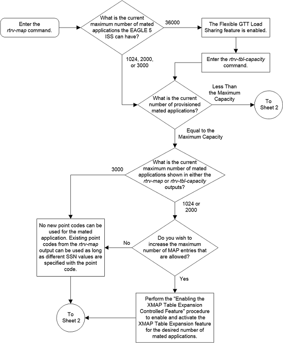
Figure 2-53 Provision a Solitary Mated Application - Sheet 2 of 11
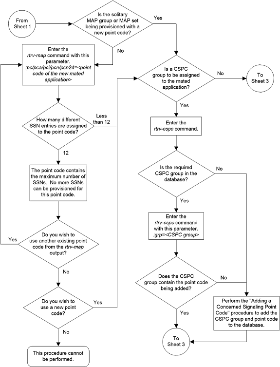
Figure 2-54 Provision a Solitary Mated Application - Sheet 3 of 11
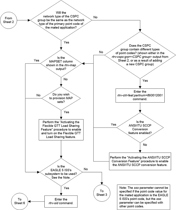
Figure 2-55 Provision a Solitary Mated Application - Sheet 4 of 11
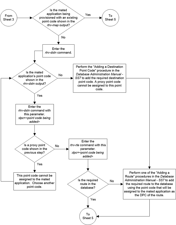
Figure 2-56 Provision a Solitary Mated Application - Sheet 5 of 11
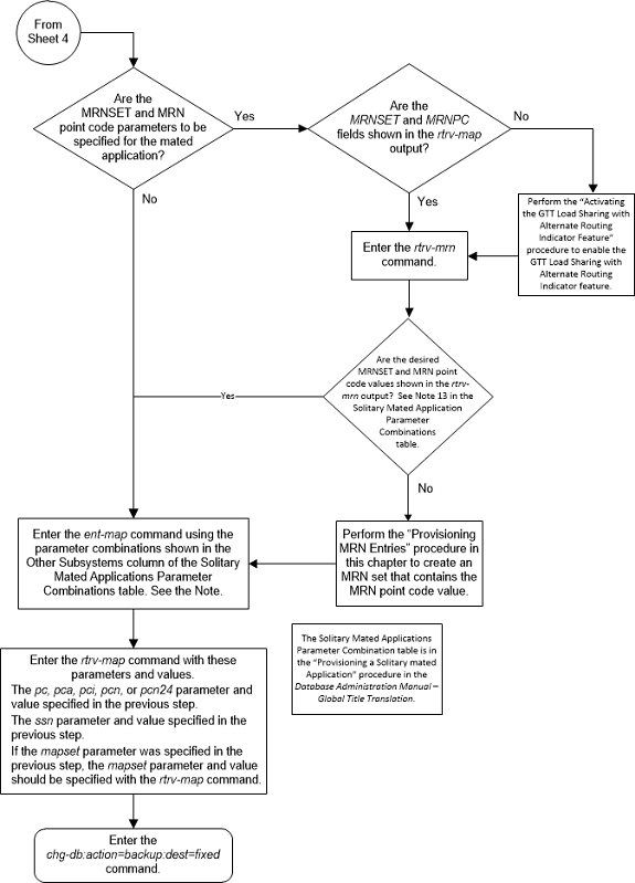
Figure 2-57 Provision a Solitary Mated Application - Sheet 6 of 11
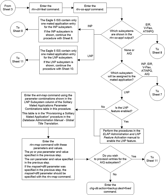
Figure 2-58 Provision a Solitary Mated Application - Sheet 7 of 11
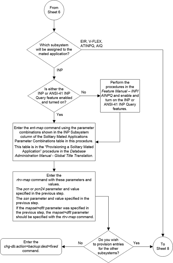
Figure 2-59 Provision a Solitary Mated Application - Sheet 8 of 11
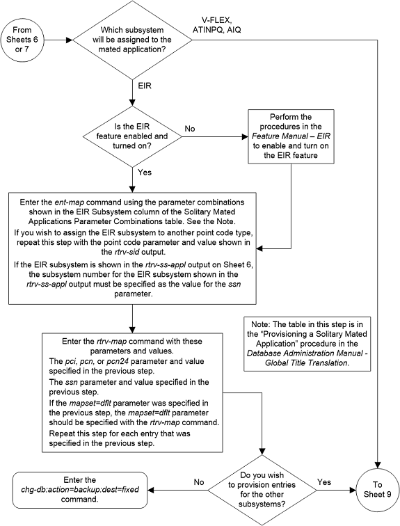
Figure 2-60 Provision a Solitary Mated Application - Sheet 9 of 11
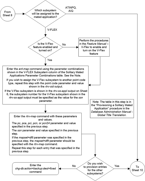
Figure 2-61 Provision a Solitary Mated Application - Sheet 10 of 11
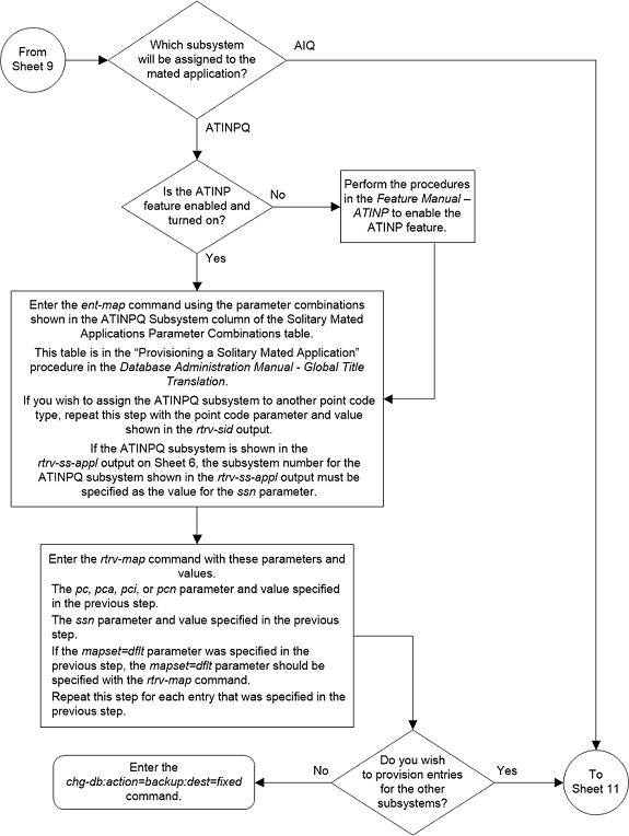
Figure 2-62 Provision a Solitary Mated Application - Sheet 11 of 11
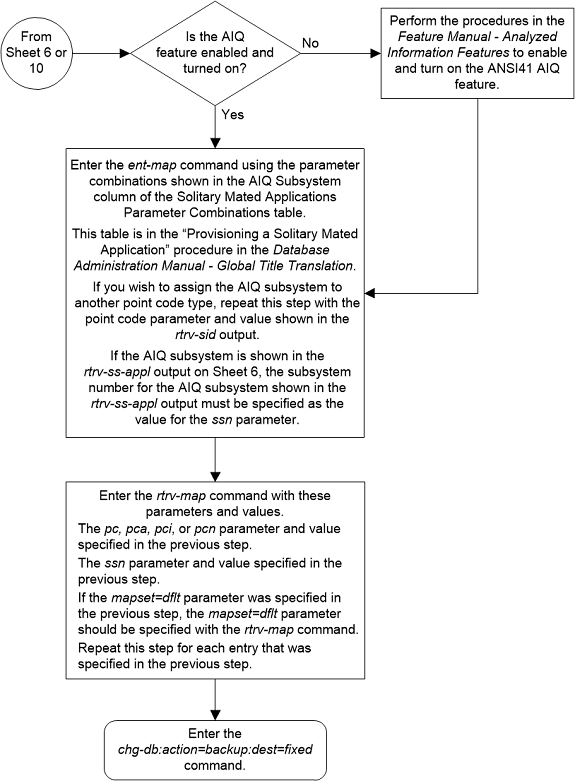
Provisioning a Dominant Mated Application
This procedure is used to provision a dominant mated
application in the database using the
ent-map and
chg-map commands. A dominant mated
application is a mated application containing entries whose RC (relative cost)
values are unique. The
ent-map and
chg-map commands use these parameters
to provision a dominant mated application.
:pc/pca/pci/pcn/pcn24 –
The point code of the primary signaling point that is to receive the message.
:mpc/mpca/mpci/mpcn/mpcn24 – The point code of the
backup signaling point that is to receive the message.
Note:
The point codes can be either an ANSI point code (pc/pca,
mpc/mpca), ITU-I or ITU-I spare point code (pci,
mpci), a 14-bit ITU-N or 14-bit ITU-N
spare point code (pcn,
mpcn), or a 24-bit ITU-N (pcn24,
mpcn24) point code.
Note:
Refer to Chapter 2, Configuring Destination Tables in Database Administration - SS7 User's Guide for a definition of the point code types that are used on the EAGLE and for a definition of the different formats that can be used for ITU national point codes.:ssn – Subsystem number
– the subsystem address of the primary point code that is to receive the
message. The value for this parameter is 2 to 255.
:mssn – Mate subsystem
number – the subsystem address of the backup point code that is to receive the
message. The value for this parameter is 2 to 255.
:rc – The relative cost
value of the primary point code and subsystem, defined by the
pc/pca/pci/pcn/pcn24 and
ssn parameters. The
rc parameter has a range of values
from 0 to 99, with the default value being 10.
:materc – The relative
cost value of the backup point code and subsystem, defined by the
mpc/mpca/mpci/mpcn/mpcn24 and
mssn parameters. The
materc parameter has a range of values
from 0 to 99, with the default value being 50.
:grp – The name of the
concerned signaling point code (CSPC) group that contains the point codes that
should be notified of the subsystem status. This parameter applies to both
RPCs/SSNs. The value for this parameter is shown in the
rtrv-cspc output. If the desired value
is not shown in the
rtrv-cspc output, perform the
Adding a Concerned Signaling Point Code
procedure to add the desired group. If this parameter is not specified, then a
CSPC group name is not specified for the mated application.
:mrc – Message routing
under congestion – defines the handling of Class 0 messages during congestion
conditions. The value for this parameter is
yes or
no. The default value for ANSI
dominant mated applications is
yes. The default value for ITU
dominant mated applications is
no.
:srm – Subsystem
routing messages – defines whether subsystem routing messages (SBR, SNR) are
transmitted between the mated applications.
:sso – Subsystem Status
Option – defines whether the subsystem status option is on or off. This
parameter allows the user the option to have the specified subsystem marked as
prohibited even though an MTP-RESUME message has been received by the
indicating that the specified point code is allowed. The
sso parameter cannot be specified if
the
pc/pca/pci/pcn/pcn24 value is the
EAGLE’s true point code, shown in the
rtrv-sid output. The value for this
parameter is
on or
off. The default value is
off.
:mapset – The MAP set
ID that the mated applications are assigned to. This parameter can be specified
only if the Flexible GTT Load Sharing feature is enabled. This parameter must
be specified if the Flexible GTT Load Sharing feature is enabled. If the
Flexible GTT Load Sharing feature is enabled, the point code and subsystem
specified for the global title translation must be assigned to the MAP set
specified by this parameter. The status of the Flexible GTT Load Sharing
feature is shown in the
rtrv-ctrl-feat output. To enable the
Flexible GTT Load Sharing feature, perform the
Activating the Flexible GTT Load Sharing Feature
procedure.
The
mapset parameter has three values:
dflt– to assign the MAP to the default MAP set. This value can be specified with both theent-mapandchg-mapcommands.new– to assign the mated application to a new MAP set. This value can be specified only with theent-mapcommand.- the specific number of an existing MAP set if you are
assigning the mated application to an existing MAP set. This value can be
specified only with the
chg-mapcommand.
Refer to the Provisioning a MAP Set section for information on provisioning MAP sets.
:mrnset – The MRN set
ID that is being assigned to the mated application. This is the MRN set from
which alternate routing indicator searches are performed.
:mrnpc/mrnpca/mrnpci/mrnpcn/mrnpcn24 – The point code
assigned to the
mrnset that is being assigned to the
MAP set.
The current values of the
mrnset and
:mrnpc/mrnpca/mrnpci/mrnpcn/mrnpcn24
parameters are shown in the
rtrv-map output only if the Flexible
GTT Load Sharing and the GTT Load Sharing with Alternate Routing Indicator
features are enabled.
The new values for the
mrnset and
mrnpc/mrnpca/mrnpci/mrnpcn/mrnpcn24
parameters must be shown in the
rtrv-mrn output.
The network type of the
pc/pca/pci/pcn/pcn24 and
mrnpc/mrnpca/mrnpci/mrnpcn/mrnpcn24
parameter values must be compatible, as shown in
Table 2-41.
Table 2-41 MAP and MRN Point Code Parameter Combinations
| MAP Point Code Parameter | MRN Point Code Parameter |
|---|---|
| pc/pca | mrnpc/mrnpca |
| pci or pcn (See Notes 1 and 2) | mrnpci or mrnpcn (See Notes 1 and 2) |
| pcn24 | mrnpcn24 |
|
Notes: 1. If the network type of the MAP point code parameter is
ITU-I ( 2. If the network type of the MAP point code parameter is
ITU-N ( |
|
If the Weighted GTT Load Sharing feature is enabled,
shown by the columns
WT,
%WT, and
THR in the
rtrv-map output, the parameters
wt,
mwt, and
thr cannot be specified for a dominant
mated application. If you wish to use these parameters to provision a mated
application, perform one of these procedures:
- Provisioning a Load Shared Mated Application
- Provisioning a Combined Dominant/Load Shared Mated Application.
A dominant mated application can contain up to 128 point
codes and subsystems, a primary point code and subsystem, and up to 31 mated
point codes and subsystems. When a new dominant mated application is added to
the database, the first two entries, the primary point code and subsystem and a
mate point code and subsystem are added using the
ent-map command. All other mated point
code and subsystem entries that are being assigned to the primary point code
and subsystem are added to the dominant mated application using the
chg-map command.
All the point codes and subsystems in a dominant mated application have different relative cost values, with the primary point code and subsystem having the lowest relative cost value. All traffic is routed to the primary point code and subsystem, if it is available. If the primary point code and subsystem becomes unavailable, the traffic is routed to highest priority backup point code and subsystem that is available. When the primary point code and subsystem becomes available again, the traffic is then routed back to the primary point code and subsystem.
If the Flexible GTT Load Sharing feature is not enabled, the primary point code and subsystem number or the mate point code and mate subsystem number combination can be in the database only once. If the Flexible GTT Load Sharing feature is enabled, the primary point code and subsystem number or mate point code and mate subsystem number combination can be in multiple MAP sets, but can be in the default MAP set only once. Refer to the Provisioning a MAP Set section for information on provisioning MAP sets.
The point codes specified in the
ent-map or
chg-map commands (pc/pca,
pci,
pcn, or
pcn24, and
mpc/mpca,
mpci,
mpcn, or
mpcn24) must be either a full point
code in the routing point code table or the EAGLE’s true point code. Cluster
point codes or network routing point codes cannot be specified with this
command. The
rtrv-rte command can be used to verify
the point codes in the routing table. The point codes in the routing table are
shown in the
DPCA,
DPCI,
DPCN, or
DPCN24 fields of the
rtrv-rte command output. The EAGLE’s
true point code is shown in the
PCA,
PCI,
PCN, or
PCN24 fields of the
rtrv-sid command output.
A dominant mated application can be provisioned with a point code that is assigned to other mated applications as long as the SSN is not assigned to other mated applications. A point code can be assigned to maximum of 12 different SSNs.
If the EAGLE’s true point code is specified in the mated application, it must be the primary point code. The relative cost value assigned to this point code must be the lowest value in the mated application. If the Flexible GTT Load Sharing feature is enabled, the mated application containing the EAGLE’s true point code can be assigned only to the default MAP set.
A mated application containing the LNP subsystem can
contain only ANSI point codes. The primary point code (pc or
pca) must be the EAGLE’s true ANSI
point code. The LNP feature must be enabled for a quantity greater than zero.
A mated application containing the INP subsystem can
contain only 14-bit ITU-N point codes, 14-bit ITU-N spare point codes, or
24-bit ITU-N point codes. The primary point code (pcn or
pcn24) must be the EAGLE’s true 14-bit
ITU-N point code, 14-bit ITU-N spare point code, or 24-bit ITU-N point code.The
INP or ANSI-41 INP Query feature must be enabled and turned on. The EAGLE can
contain either 14-bit ITU-N point codes (spare or non-spare point codes) or
24-bit ITU-N point codes. Both types of point codes cannot be present on the
EAGLE at the same time.
A mated application containing the EIR subsystem can
contain only ITU-I point codes, ITU-I spare point codes, 14-bit ITU-N point
codes, 14-bit ITU-N spare point codes, or 24-bit ITU-N point codes. The primary
point code (pci,
pcn, or
pcn24) must be the EAGLE’s true ITU-I
point code, ITU-I spare point code, 14-bit ITU-N point code, 14-bit ITU-N spare
point code, or 24-bit ITU-N point code. The EIR feature must be enabled and
turned on. The EAGLE can contain either 14-bit ITU-N point codes (spare or
non-spare point codes) or 24-bit ITU-N point codes. Both types of point codes
cannot be present on the EAGLE at the same time.
A mated application containing the VFLEX subsystem can
contain any type of point code. The primary point code (pc,
pca,
pci,
pcn, or
pcn24) must be the EAGLE’s true point
code. The V-Flex feature must be enabled and turned on.The EAGLE can contain
either 14-bit ITU-N point codes (spare or non-spare point codes) or 24-bit
ITU-N point codes. Both types of point codes cannot be present on the EAGLE at
the same time.
A mated application containing the ATINPQ subsystem can
contain only ANSI point codes, ITU-I point codes, ITU-I spare point codes,
14-bit ITU-N point codes, or 14-bit ITU-N spare point codes. The primary point
code (pc,
pca,
pci, or
pcn) must be the EAGLE’s true ANSI
point code, ITU-I point code, ITU-I spare point code, 14-bit ITU-N point code,
or 14-bit ITU-N spare point code. The ATINP feature must be enabled.
A mated application containing the AIQ subsystem can contain any of the EAGLE’s true point codes. The ANSI41 AIQ feature must be enabled. The EAGLE can contain either 14-bit ITU-N point codes (spare or non-spare point codes) or 24-bit ITU-N point codes. Both types of point codes cannot be present on the EAGLE at the same time.
The EAGLE can contain multiple entries that contain the
EAGLE's true point code, shown in the
rtrv-sid output.
Table 2-42
shows the numbers of entries that can be provisioned based on the type of point
code.
Table 2-42 Maximum Number of True Point Code Entries
| True Point Code Type | Maximum Number of Entries |
|---|---|
| ANSI |
1 - for the LNP subsystem 2 - one entry for the LNP subsystem and one entry for the AIQ subsystem 3 - one entry for the ATINPQ subsystem, one entry for the V-FLEX subsystem, and one entry for the AIQ subsystem The LNP subsystem cannot be used if the ATINPQ, EIR, INP, and V-FLEX subsystems are used. |
| ITU-I |
4 - one entry for the ATINPQ subsystem, one entry for the EIR subsystem, one entry for the V-FLEX subsystem, and one entry for the AIQ subsystem |
| ITU-N |
5 - one entry for the ATINPQ subsystem, one entry for the EIR subsystem, one entry for the INP subsystem, one entry for the V-FLEX subsystem, and one entry for the AIQ subsystem |
For mated applications containing ANSI or 24-bit ITU-N
point codes, or the EAGLE's true point code, the format of the point codes
specified in the
ent-map command must be the same. For
example, if the primary point code is a 24-bit ITU-N point code (pcn24), the mate point code must be a 24-bit ITU-N
point code (mpcn24). The mate point codes of
mated applications containing either ITU-I, ITU-I spare, 14-bit ITU-N, or
14-bit ITU-N spare primary point codes do not have to be the same format as the
primary point code. The mate point codes of these mated applications can be a
mixture of ITU-I, ITU-I spare, 14-bit ITU-N, or 14-bit ITU-N spare point codes.
The format of the point codes in the CSPC group
specified with the
grp parameter must be the same as the
primary point code specified with the
ent-map command only if the ANSI/ITU
SCCP Conversion feature is not enabled. If the ANSI/ITU SCCP Conversion feature
is enabled, the CSPC group may contain a mixture of point code types (refer to
the
Adding a Concerned Signaling Point Code
procedure ), and the network type of the CSPC group can be different from the
network type of the primary point code of the mated application. The status of
the ANSI/ITU SCCP Conversion feature can be verified with the
rtrv-ctrl-feat command.
The values for the primary point code and subsystem
combination (pc/ssn) cannot be the same as the mated point code and
subsystem combination (mpc/mssn). However, the primary and mated point codes can
be the same as long as the subsystem numbers are different.
If a mate point code (mpc/mpca/mpci/mpcn/mpcn24) is specified, the
mssn parameter must be specified.
If the
mssn parameter is specified, the mate
point code (mpc/mpca/mpci/mpcn/mpcn24) must be
specified.
If the
grp,
srm,
mrc, and
sso parameter values are specified,
and the specified point code and SSN is assigned to multiple mated
applications, the
grp,
srm,
mrc, and
sso values for all mated applications
containing the specified point code and SSN will be changed to the values
specified in this procedure.
The EAGLE can contain 1024, 2000, or 3000 mated applications. The EAGLE default is 1024 mated applications. This quantity can be increased to 2000 by enabling the feature access key for part number 893-0077-01, or to 3000 by enabling the feature access key for part number 893-0077-10. For more information on enabling these feature access keys, refer to the Enabling the XMAP Table Expansion Feature procedure.
Provisioning a MAP Set
The Flexible GTT Load Sharing feature provides the ability to define multiple load sharing sets in the MAP table where the same point code and subsystem can be assigned to different load sharing sets.
The MAP table contains specific load sharing sets, designated by numbers, and a default MAP set.
Flexible Final GTT Load Sharing provides flexible load sharing for global title translations defined in the GTT table and not for the MPS-based features. The MPS-based features do not support the MAP set ID parameter. The MPS-based features perform lookups for load sharing in the default MAP set and the GTT table. The entries in the GTT table can be linked to a MAP set ID, allowing lookups in a specific MAP set other than the default MAP set.
Any MAP entries that were provisioned in the database before the Flexible GTT Load Sharing feature is enabled are placed in the default MAP set when the Flexible GTT Load Sharing feature is enabled.
To provision entries in the default MAP set, the
mapset=dflt parameter must be
specified with the
ent-map or
chg-map commands.
To provision entries in an existing MAP set other than
the default MAP set, the
mapset=<MAP set ID> parameter
must be specified with the
chg-map command. Provisioning entries
in an existing MAP set can be performed only with the
chg-map command.
To provision entries in a new MAP set, the
mapset=new parameter must be specified
with the
ent-map command. The
mapset=new parameter can be specified
only with the
ent-map command. When the
ent-map command is executed with the
mapset=new parameter, the new MAP set
ID is automatically generated and displayed in the output of the
ent-map command as follows.
New MAPSET Created : MAPSETID = <new MAP set ID>A MAP set, other than the default MAP set, is a MAP group provisioned with the MAP set ID and can contain a maximum of 32 point codes.
The default MAP set can contain multiple MAP groups. The point code and subsystem number combination can appear only once in the default MAP set. The point code can appear in multiple MAP groups in the default MAP set with different subsystem numbers.
The point code and subsystem number combination provisioned in a MAP set can be provisioned in multiple MAP sets. All the point code and subsystem number combinations in a MAP set must be different.
Canceling the
RTRV-MAP Command
Because the
rtrv-map command used in this
procedure can output information for a long period of time, the
rtrv-map command can be canceled and
the output to the terminal stopped. There are three ways that the
rtrv-map command can be canceled.
- Press the
F9function key on the keyboard at the terminal where thertrv-mapcommand was entered. - Enter the
canc-cmdwithout thetrmparameter at the terminal where thertrv-mapcommand was entered. - Enter the
canc-cmd:trm=<xx>, where<xx>is the terminal where thertrv-mapcommand was entered, from another terminal other that the terminal where thertrv-mapcommand was entered. To enter thecanc-cmd:trm=<xx>command, the terminal must allow Security Administration commands to be entered from it and the user must be allowed to enter Security Administration commands. The terminal’s permissions can be verified with thertrv-secu-trmcommand. The user’s permissions can be verified with thertrv-userorrtrv-secu-usercommands.
For more information about the
canc-cmd command, refer to
Commands User's Guide.
Figure 2-63 Provision a Dominant Mated Application- Sheet 1 of 17
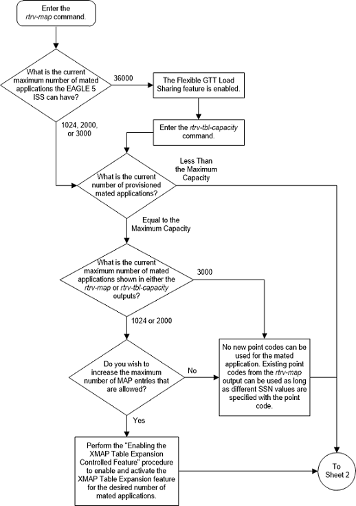
Figure 2-64 Provision a Dominant Mated Application - Sheet 2 of 17
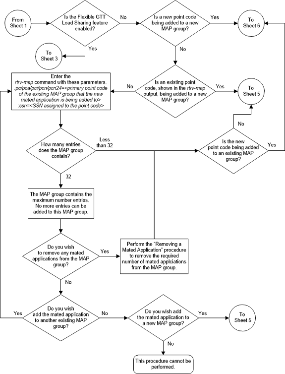
Figure 2-65 Provision a Dominant Mated Application - Sheet 3 of 17
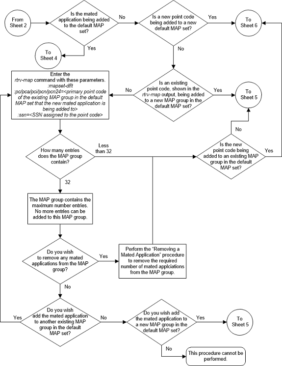
Figure 2-66 Provision a Dominant Mated Application - Sheet 4 of 17
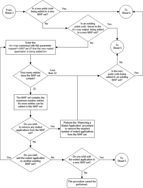
Figure 2-67 Provision a Dominant Mated Application - Sheet 5 of 17
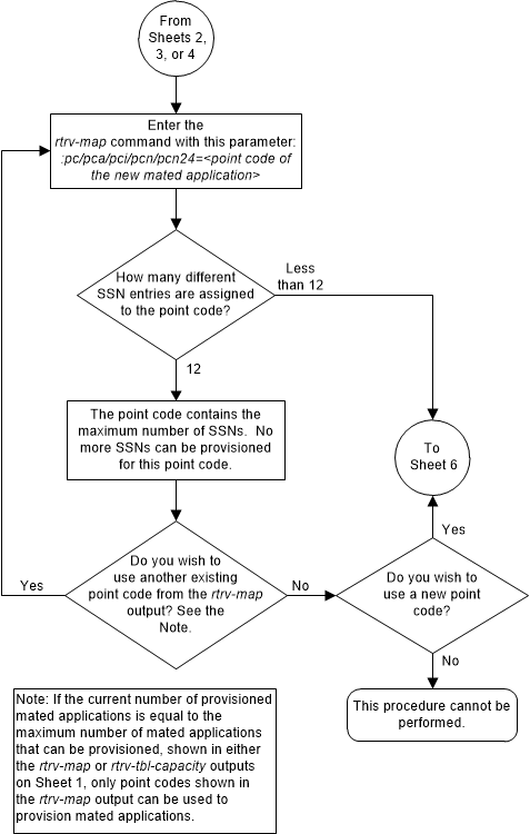
Figure 2-68 Provision a Dominant Mated Application - Sheet 6 of 17
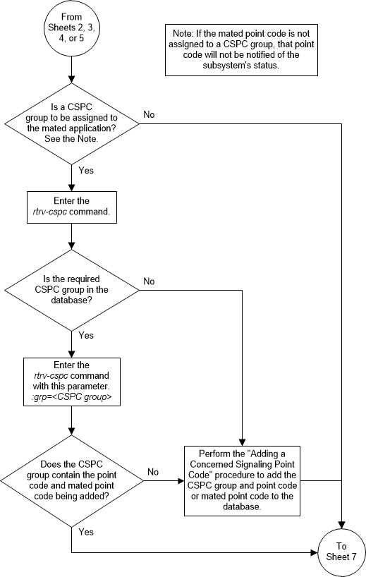
Figure 2-69 Provision a Dominant Mated Application - Sheet 7 of 17
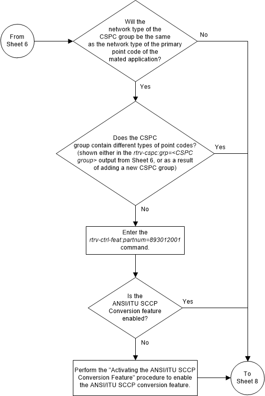
Figure 2-70 Provision a Dominant Mated Application - Sheet 8 of 17
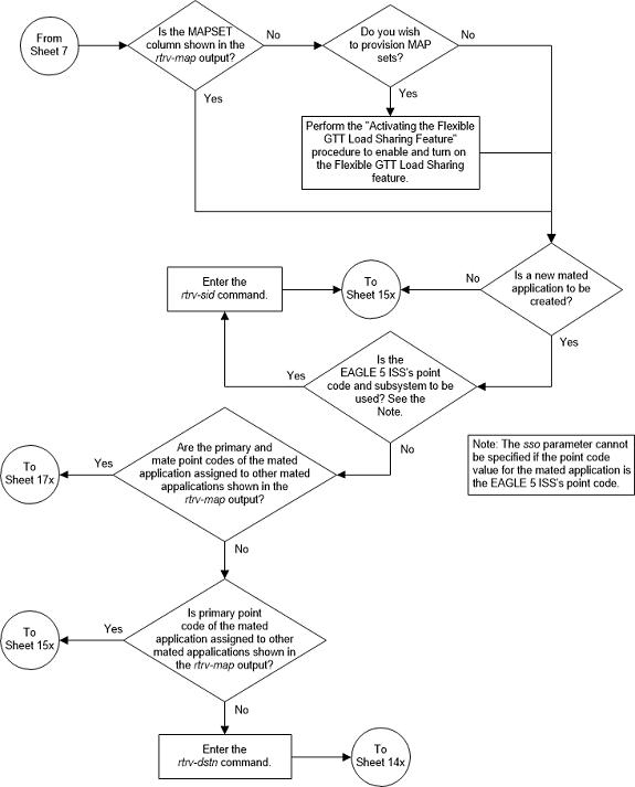
Figure 2-71 Provision a Dominant Mated Application - Sheet 9 of 17
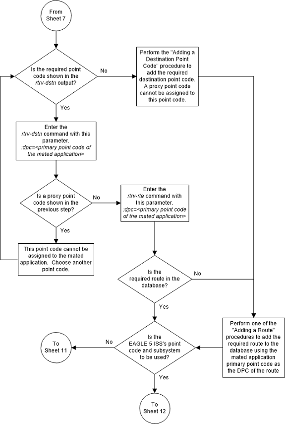
Figure 2-72 Provision a Dominant Mated Application - Sheet 10 of 17
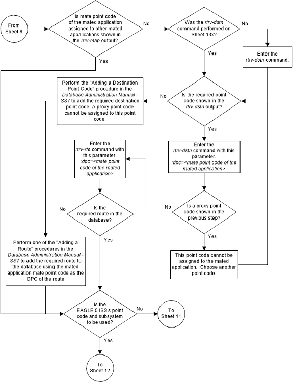
Figure 2-73 Provision a Dominant Mated Application - Sheet 11 of 17
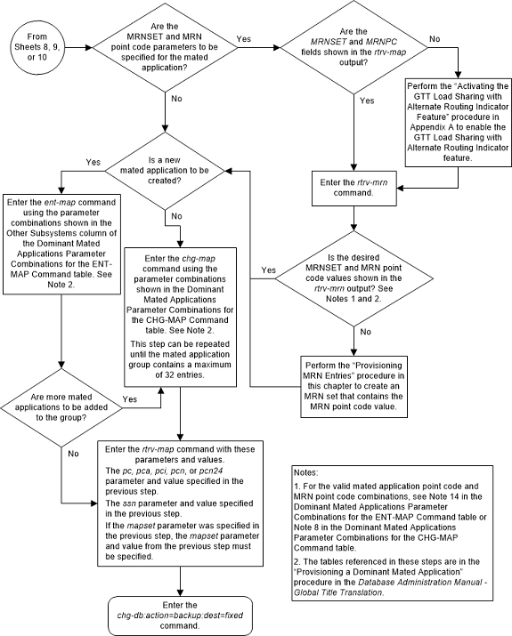
Figure 2-74 Provision a Dominant Mated Application - Sheet 12 of 17
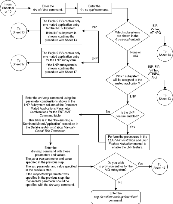
Figure 2-75 Provision a Dominant Mated Application - Sheet 13 of 17
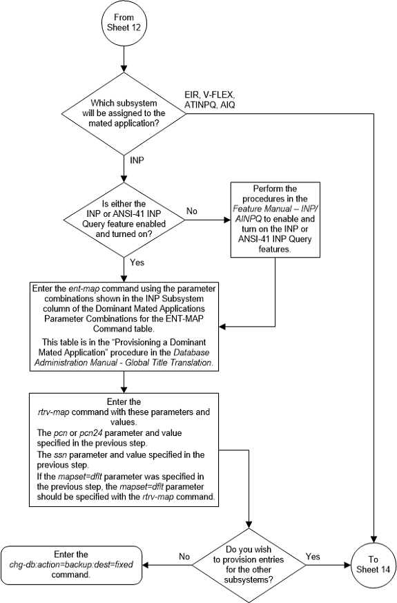
Figure 2-76 Provision a Dominant Mated Application - Sheet 14 of 17
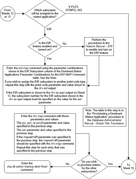
Figure 2-77 Provision a Dominant Mated Application - Sheet 15 of 17
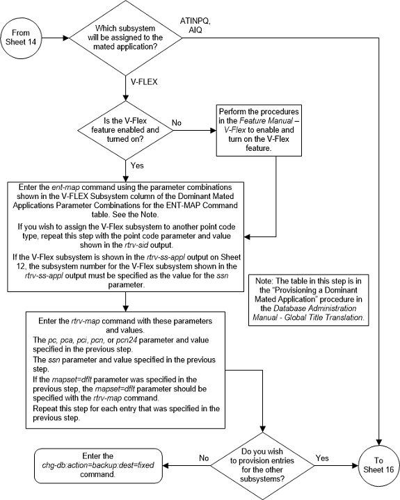
Figure 2-78 Provision a Dominant Mated Application - Sheet 16 of 17
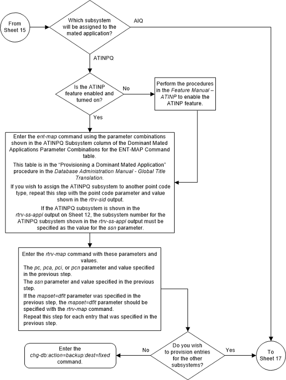
Figure 2-79 Provision a Dominant Mated Application - Sheet 17 of 17
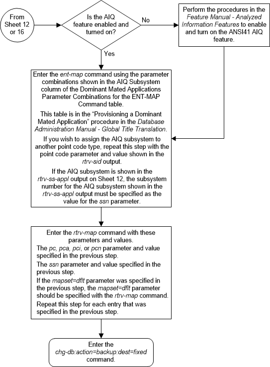
Provisioning a Load Shared Mated Application
This procedure is used to provision a load shared mated
application in the database using the
ent-map and
chg-map commands. A load shared mated
application is a mated application containing entries whose RC (relative cost)
values are equal. The
ent-map and
chg-map commands use these parameters
to provision a load shared mated application.
:pc/pca/pci/pcn/pcn24 –
The point code of the primary signaling point that is to receive the message.
:mpc/mpca/mpci/mpcn/mpcn24 – The point code of the
backup signaling point that is to receive the message.
Note:
The point codes can be either an ANSIpoint code (pc/pca,
mpc/mpca), ITU-I or ITU-I spare point code (pci,
mpci), a 14-bit ITU-N or 14-bit ITU-N
spare point code (pcn,
mpcn), or a 24-bit ITU-N (pcn24,
mpcn24) point code.
Note:
Refer to Chapter 2, Configuring Destination Tables in Database Administration - SS7 User's Guide for a definition of the point code types that are used on the EAGLE and for a definition of the different formats that can be used for ITU national point codes.:ssn – Subsystem number
– the subsystem address of the primary point code that is to receive the
message. The value for this parameter is 2 to 255.
:mssn – Mate subsystem
number – the subsystem address of the backup point code that is to receive the
message. The value for this parameter is 2 to 255.
:rc – The relative cost
value of the primary point code and subsystem, defined by the
pc/pca/pci/pcn/pcn24 and
ssn parameters. The
rc parameter has a range of values
from 0 to 99, with the default value being 10.
:materc – The relative
cost value of the backup point code and subsystem, defined by the
mpc/mpca/mpci/mpcn/mpcn24 and
mssn parameters. The
materc parameter has a range of values
from 0 to 99, with the default value being 50.
:grp – The name of the
concerned signaling point code group that contains the point codes that should
be notified of the subsystem status. This parameter applies to both RPCs/SSNs.
The value for this parameter is shown in the
rtrv-cspc output. If the desired value
is not shown in the
rtrv-cspc output, perform the
Adding a Concerned Signaling Point Code
procedure to add the desired group. If this parameter is not specified, then a
CSPC group name is not specified for the mated application.
:sso – Subsystem Status
Option – defines whether the subsystem status option is on or off. This
parameter allows the user the option to have the specified subsystem marked as
prohibited even though an MTP-RESUME message has been received by the
indicating that the specified point code is allowed. The value for this
parameter is
on or
off. The default value is
off.
:mapset – The MAP set
ID that the mated applications are assigned to. This parameter can be specified
only if the Flexible GTT Load Sharing feature is enabled. This parameter must
be specified if the Flexible GTT Load Sharing feature is enabled. If the
Flexible GTT Load Sharing feature is enabled, the point code and subsystem
specified for the global title translation must be assigned to the MAP set
specified by this parameter. The status of the Flexible GTT Load Sharing
feature is shown in the
rtrv-ctrl-feat output. To enable the
Flexible GTT Load Sharing feature, perform the
Activating the Flexible GTT Load Sharing Feature
procedure.
The
mapset parameter has three values.
dflt– to assign the MAP to the default MAP set. This value can be specified with both theent-mapandchg-mapcommands.new– to assign the mated application to a new MAP set. This value can be specified only with theent-mapcommand.- The specific number of an existing MAP set if you are
assigning the mated application to an existing MAP set. This value can be
specified only with the
chg-mapcommand.Refer to the Provisioning a MAP Set section for information on provisioning MAP sets.
:wt – The weight value
assigned to the
pc/pca/pci/pcn/pcn24 parameter
value. The value of this parameter is from 1 - 99.
:mwt – The weight value
assigned to the
mpc/mpca/mpci/mpcn/mpcn24 parameter
value. The value of this parameter is from 1 - 99.
:thr – The in-service
threshold assigned to the MAP group or MAP set. The in-service threshold is the
minimum percentage (from 1 - 100) of weight that must be available for an RC
group (a group of entries in the MAP group or MAP set that have the same RC
value assigned) to be considered available to carry traffic. If the percentage
of the available weight is less than the in-service threshold, then the entire
RC group is considered unavailable for traffic. If the percentage of the
available weight is equal to or greater than the in-service threshold, then the
RC group is considered available, and traffic can be sent to any available
entity in the RC group. The value of the
thr parameter is assigned to all
entries that have the same RC (relative cost) value in the MAP group or MAP set
that contain the point code specified in the
ent-map or
chg-map command.
Refer to the Provisioning Weights and In-Service Thresholds for Mated Applications section for information on provisioning MAP groups or MAP sets with weight and in-service threshold values.
:mrnset – The MRN set
ID that is being assigned to the mated application. This is the MRN set from
which alternate routing indicator searches are performed.
:mrnpc/mrnpca/mrnpci/mrnpcn/mrnpcn24 – The point code
assigned to the
mrnset that is being assigned to the
MAP set.
The current values of the
mrnset and
:mrnpc/mrnpca/mrnpci/mrnpcn/mrnpcn24
parameters are shown in the
rtrv-map output only if the Flexible
GTT Load Sharing and the GTT Load Sharing with Alternate Routing Indicator
features are enabled.
The new values for the
mrnset and
mrnpc/mrnpca/mrnpci/mrnpcn/mrnpcn24
parameters must be shown in the
rtrv-mrn output.
The network type of the
pc/pca/pci/pcn/pcn24 and
mrnpc/mrnpca/mrnpci/mrnpcn/mrnpcn24
parameter values must be compatible, as shown in
Table 2-45.
Table 2-45 MAP and MRN Point Code Parameter Combinations
| MAP Point Code Parameter | MRN Point Code Parameter |
|---|---|
| pc/pca | mrnpc/mrnpca |
| pci or pcn (See Notes 1 and 2) | mrnpci or mrnpcn (See Notes 1 and 2) |
| pcn24 | mrnpcn24 |
|
Notes: 1. If the network type of the MAP point code parameter is
ITU-I ( 2. If the network type of the MAP point code parameter is
ITU-N ( |
|
:mrc – Message routing
under congestion – specifies whether Class 0 messages are routed during
congestion conditions. The values for this parameter are
yes and
no. This parameter can be specified
for any type of mated application, but this parameter affects only the traffic
for a dominant mated application. The default value for ANSI load shared mated
applications is
yes. The default value for ITU load
shared mated applications is
no.
:srm – Subsystem
routing messages – defines whether subsystem routing messages (SBR, SNR) are
transmitted between the mated applications. The values for this parameter are
yes and
no. The
srm=yes parameter can be specified
only for ANSI mated applications. This parameter affects traffic only on
dominant and combined dominant/load shared mated applications. The default
value for ANSI load shared mated applications is
yes. The default value for ITU load
shared mated applications is
no.
A load shared mated application can contain up to 128
point codes and subsystems, a primary point code and subsystem, and up to 31
mated point codes and subsystems. When a new load shared mated application is
added to the database, the first two entries, the primary point code and
subsystem and a mate point code and subsystem are added using the
ent-map command. All other mated point
code and subsystem entries that are being assigned to the primary point code
and subsystem are added to the load shared mated application using the
chg-map command.
All the point codes and subsystems in a load shared mated application have the same relative cost value. Traffic is shared equally between the point codes and subsystems in this mated application.
If the Flexible GTT Load Sharing feature is not enabled, the primary point code and subsystem number or the mate point code and mate subsystem number combination can be in the database only once. If the Flexible GTT Load Sharing feature is enabled, the primary point code and subsystem number or mate point code and mate subsystem number combination can be in multiple MAP sets, but can be in the default MAP set only once.. Refer to the Provisioning a MAP Set section for information on provisioning MAP sets.
The point codes specified in the
ent-map or
chg-map commands (pc/pca,
pci,
pcn, or
pcn24, and
mpc/mpca,
mpci,
mpcn, or
mpcn24) must be either a full point
code in the routing point code table. Cluster point codes or network routing
point codes cannot be specified with this command. The
rtrv-rte command can be used to verify
the point codes in the routing table. The point codes in the routing table are
shown in the
DPCA,
DPCI,
DPCN, or
DPCN24 fields of the
rtrv-rte command output. The EAGLE’s
true point code, shown in the
PCA,
PCI,
PCN, or
PCN24 fields of the
rtrv-sid command output, cannot be
specified for a load shared mated application.
A load shared mated application can be provisioned with a point code that is assigned to other mated applications as long as the SSN is not assigned to other mated applications. A point code can be assigned to maximum of 12 different SSNs.
For mated applications containing ANSI or 24-bit ITU-N
point codes, or the EAGLE's true point code, the format of the point codes
specified in the
ent-map command must be the same. For
example, if the primary point code is a 24-bit ITU-N point code (pcn24), the mate point code must be a 24-bit ITU-N
point code (mpcn24). The mate point codes of
mated applications containing either ITU-I, ITU-I spare, 14-bit ITU-N, or
14-bit ITU-N spare primary point codes do not have to be the same format as the
primary point code. The mate point codes of these mated applications can be a
mixture of ITU-I, ITU-I spare, 14-bit ITU-N, or 14-bit ITU-N spare point codes.
The format of the point codes in the CSPC group
specified with the
grp parameter must be the same as the
primary point code specified with the
ent-map command only if the ANSI/ITU
SCCP Conversion feature is not enabled. If the ANSI/ITU SCCP Conversion feature
is enabled, the CSPC group may contain a mixture of point code types (refer to
the
Adding a Concerned Signaling Point Code
procedure), and the network type of the CSPC group can be different from the
network type of the primary point code of the mated application. The status of
the ANSI/ITU SCCP Conversion feature can be verified with the
rtrv-ctrl-feat command.
The values for the primary point code and subsystem
combination (pc/ssn) cannot be the same as the mated point code and
subsystem combination (mpc/mssn). However, the primary and mated point codes can
be the same as long as the subsystem numbers are different.
If a mate point code (mpc/mpca/mpci/mpcn/mpcn24) is specified, the
mssn parameter must be specified.
If the
mssn parameter is specified, the mate
point code (mpc/mpca/mpci/mpcn/mpcn24) must be
specified.
If the
grp,
srm,
mrc, and
sso parameter values are specified,
and the specified point code and SSN is assigned to multiple mated
applications, the
grp,
srm,
mrc, and
sso values for all mated applications
containing the specified point code and SSN will be changed to the values
specified in this procedure.
The EAGLE can contain 1024, 2000, or 3000 mated applications. The EAGLE default is 1024 mated applications. This quantity can be increased to 2000 by enabling the feature access key for part number 893-0077-01, or to 3000 by enabling the feature access key for part number 893-0077-10. For more information on enabling these feature access keys, refer to the Enabling the XMAP Table Expansion Feature procedure.
Provisioning a MAP Set
The Flexible GTT Load Sharing feature provides the ability to define multiple load sharing sets in the MAP table where the same point code and subsystem can be assigned to different load sharing sets.
The MAP table contains specific load sharing sets, designated by numbers, and a default MAP set.
Flexible Final GTT Load Sharing provides flexible load sharing for global title translations defined in the GTT table and not for the MPS-based features. The MPS-based features do not support the MAP set ID parameter. The MPS-based features perform lookups for load sharing in the default MAP set and the GTT table. The entries in the GTT table can be linked to a MAP set ID, allowing lookups in a specific MAP set other than the default MAP set.
Any MAP entries that were provisioned in the database before the Flexible GTT Load Sharing feature is enabled are placed in the default MAP set when the Flexible GTT Load Sharing feature is enabled.
To provision entries in the default MAP set, the
mapset=dflt parameter must be
specified with the
ent-map or
chg-map commands.
To provision entries in an existing MAP set other than
the default MAP set, the
mapset=<MAP set ID> parameter
must be specified with the
chg-map command. Provisioning entries
in an existing MAP set can be performed only with the
chg-map command.
To provision entries in a new MAP set, the
mapset=new parameter must be specified
with the
ent-map command. The
mapset=new parameter can be specified
only with the
ent-map command. When the
ent-map command is executed with the
mapset=new parameter, the new MAP set
ID is automatically generated and displayed in the output of the
ent-map command as follows.
New MAPSET Created : MAPSETID = <new MAP set ID>A MAP set, other than the default MAP set, is a MAP group provisioned with the MAP set ID and can contain a maximum of 128 point codes.
The default MAP set can contain multiple MAP groups. The point code and subsystem number combination can appear only once in the default MAP set. The point code can appear in multiple MAP groups in the default MAP set with different subsystem numbers.
The point code and subsystem number combination provisioned in a MAP set can be provisioned in multiple MAP sets. All the point codes in a MAP set must be different.
Provisioning Weights and In-Service Thresholds for Mated Applications
Weighted GTT Load Sharing allows unequal traffic loads to be provisioned in MAP load sharing groups or MAP load sharing sets. This feature also allows provisioning control over load sharing groups or sets so that if insufficient capacity within the load sharing group or set is available, the load sharing group or set is not used.
To provision the weight values and in-service threshold
values for MAP groups or MAP sets in this procedure, the
wt,
mwt, and
thr parameters are used.
The
wt,
mwt, and
thr parameters can be used only:
- If the MAP group or MAP set is either a load shared or combined dominant/load shared MAP group or MAP set.
- If the Weighted GTT Load Sharing feature is enabled and turned on.
The status of the Weighted GTT Load Sharing feature can
be verified by entering the
rtrv-ctrl-feat command. If the
Weighted GTT Load Sharing feature is not enabled or not turned on, perform the
Activating the Weighted GTT Load Sharing Feature
procedure to enable and turn on the Weighted GTT Load Sharing feature.
If either the
wt or
mwt parameters are specified with the
ent-map command, both parameters must
be specified with the
ent-map command.
To assign an in-service threshold value to the entries
of a MAP group or MAP set that contains the point code value specified in the
ent-map command, use the
thr parameter with the
wt and
mwt parameters. When the
thr parameter is specified with the
ent-map command, the in-service
threshold value is assigned to both entries specified in the
ent-map command. The
thr parameter cannot be specified with
the
chg-map command when adding additional
entries to the MAP group or MAP set. When additional entries are added to the
MAP group or MAP set with the
chg-map command, the
thr value that was specified in the
ent-map command is assigned to the
additional entries. For information on using the
thr parameter with the
chg-map command, refer to the
Changing the Weight and In-Service Threshold Values of a Mated Application
procedure.
The
thr parameter does not have to be
specified with the
ent-map command. If the
thr parameter is not specified with
the
ent-map command, the
THR parameter value for the MAP group
or MAP set is set to 1.
Specifying the
wt and
mwt parameters assigns a weight value
to the point codes specified in the
ent-map command. The
wt parameter value is assigned to the
mpc/mpca/mpci/mpcn/mpcn24 parameter
value and the
mwt parameter value is assigned to the
mpc/mpca/mpci/mpcn/mpcn24 parameter
value.
When additional entries are added to the MAP group or
MAP set with the
chg-map command, and the MAP group or
MAP set entries have weight and in-service threshold values assigned, a weight
value must be assigned to the
mpc/mpca/mpci/mpcn/mpcn24 parameter
value using the
mwt parameter.
The
wt parameter does not have to be
specified with the
chg-map command. If the
wt parameter is specified with the
chg-map command, the weight value for
the
pc/pca/pci/pcn/pcn24 parameter is
not changed.
If the
wt parameter is specified with the
chg-map command and the
wt value is the same as the value
currently assigned to the
pc/pca/pci/pcn/pcn24 parameter,
the weight value for the
pc/pca/pci/pcn/pcn24 parameter is
not changed.
If the
wt parameter is specified with the
chg-map command and the
wt value is different from the value
currently assigned to the
pc/pca/pci/pcn/pcn24 parameter,
the weight value for the
pc/pca/pci/pcn/pcn24 parameter is
changed to the new
wt value.
The weight values assigned to the entires in the MAP
group or MAP set are shown in the
WT column in the
rtrv-map output.
The in-service threshold values assigned to the entires
in the MAP group or MAP set are shown in the
THR column in the
rtrv-map output.
The
%WT column in the
rtrv-map output shows the percentage
of the traffic the particular entry in the MAP group or MAP set will handle.
The
WT,
%WT, and
THR columns are shown in the
rtrv-map output only if the Weighted
GTT Load Sharing feature is enabled and turned on.
For more information on the Weighted GTT Load Sharing feature, refer to the Weighted GTT Load Sharing section.
Canceling the
RTRV-MAP Command
Because the
rtrv-map command used in this
procedure can output information for a long period of time, the
rtrv-map command can be canceled and
the output to the terminal stopped. There are three ways that the
rtrv-map command can be canceled.
- Press the
F9function key on the keyboard at the terminal where thertrv-mapcommand was entered. - Enter the
canc-cmdwithout thetrmparameter at the terminal where thertrv-mapcommand was entered. - Enter the
canc-cmd:trm=<xx>, where<xx>is the terminal where thertrv-mapcommand was entered, from another terminal other that the terminal where thertrv-mapcommand was entered. To enter thecanc-cmd:trm=<xx>command, the terminal must allow Security Administration commands to be entered from it and the user must be allowed to enter Security Administration commands. The terminal’s permissions can be verified with thertrv-secu-trmcommand. The user’s permissions can be verified with thertrv-userorrtrv-secu-usercommands.
For more information about the
canc-cmd command, refer to
Commands User's Guide.
Figure 2-80 Provision a Load Shared Mated Application - Sheet 1 of 11
Figure 2-81 Provision a Load Shared Mated Application - Sheet 2 of 11
Figure 2-82 Provision a Load Shared Mated Application - Sheet 3 of 11
Figure 2-83 Provision a Load Shared Mated Application - Sheet 4 of 11
Figure 2-84 Provision a Load Shared Mated Application - Sheet 5 of 11
Figure 2-85 Provision a Load Shared Mated Application - Sheet 6 of 11
Figure 2-86 Provision a Load Shared Mated Application - Sheet 7 of 11
Figure 2-87 Provision a Load Shared Mated Application - Sheet 8 of 11
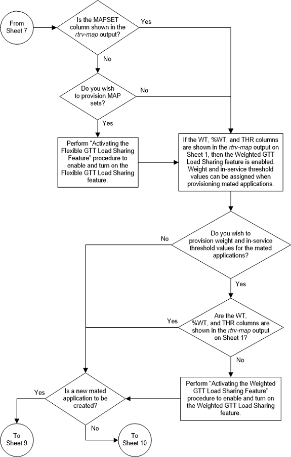
Figure 2-88 Provision a Load Shared Mated Application - Sheet 9 of 11
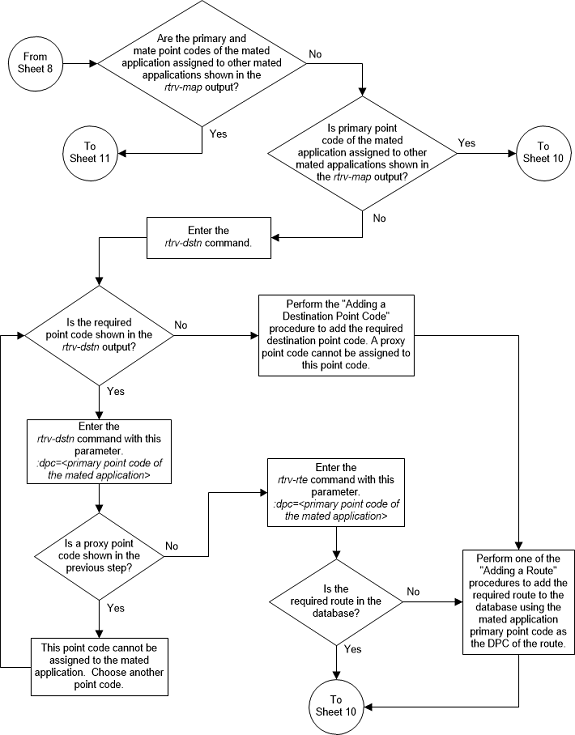
Figure 2-89 Provision a Load Shared Mated Application - Sheet 10 of 11
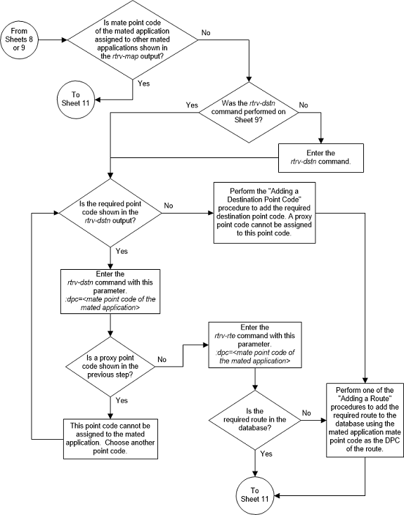
Figure 2-90 Provision a Load Shared Mated Application - Sheet 11 of 11
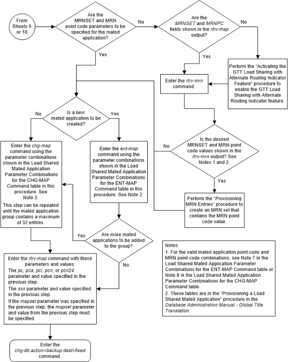
Provisioning a Combined Dominant/Load Shared Mated Application
This procedure is used to provision a combined
dominant/load shared mated application in the database using the
ent-map and
chg-map commands. A combined
dominant/load shared mated application is a mated application that contains a
minimum of two RC (relative cost) values that are equal and a minimum of one RC
value that is different. The
ent-map and
chg-map commands use these parameters
to provision a combined dominant/load shared mated application.
:pc/pca/pci/pcn/pcn24 –
The point code of the primary signaling point that is to receive the message.
:mpc/mpca/mpci/mpcn/mpcn24 – The point code of the
backup signaling point that is to receive the message.
Note:
The point codes can be either an ANSI point code (pc/pca,
mpc/mpca), ITU-I or ITU-I spare point code (pci,
mpci), a 14-bit ITU-N or 14-bit ITU-N
spare point code (pcn,
mpcn), or a 24-bit ITU-N (pcn24,
mpcn24) point code.
Note:
Refer to Chapter 2, Configuring Destination Tables in Database Administration - SS7 User's Guide for a definition of the point code types that are used on the EAGLE and for a definition of the different formats that can be used for ITU national point codes.:ssn – Subsystem number
– the subsystem address of the primary point code that is to receive the
message. The value for this parameter is 2 to 255.
:mssn – Mate subsystem
number – the subsystem address of the backup point code that is to receive the
message. The value for this parameter is 2 to 255.
:rc – The relative cost
value of the primary point code and subsystem, defined by the
pc/pca/pci/pcn/pcn24 and
ssn parameters. The
rc parameter has a range of values
from 0 to 99, with the default value being 10.
:materc – The relative
cost value of the backup point code and subsystem, defined by the
mpc/mpca/mpci/mpcn/mpcn24 and
mssn parameters. The
materc parameter has a range of values
from 0 to 99, with the default value being 50.
:grp – The name of the
concerned signaling point code group that contains the point codes that should
be notified of the subsystem status. This parameter applies to both RPCs/SSNs.
The value for this parameter is shown in the
rtrv-cspc output. If the desired value
is not shown in the
rtrv-cspc output, perform
Adding a Concerned Signaling Point Code
to add the desired group. If this parameter is not specified, then a CSPC group
name is not specified for the mated application.
:mrc – Message routing
under congestion – defines the handling of Class 0 messages during congestion
conditions. The value for this parameter is
yes or
no. This parameter can be specified
for any type of mated application, but this parameter affects only the traffic
for a dominant mated application. The default value for ANSI combined
dominant/load shared mated applications is
yes. The default value for ITU
combined dominant/load shared mated applications is
no.
:srm – Subsystem
routing messages – defines whether subsystem routing messages (SBR, SNR) are
transmitted between the mated applications. The value for this parameter is
yes or
no. The
srm=yes parameter can be specified
only for ANSI mated applications. The default value for ANSI combined
dominant/load shared mated applications is
yes. The default value for ITU
combined dominant/load shared mated applications is
no.
:sso – Subsystem Status
Option – defines whether the subsystem status option is on or off. This
parameter allows the user the option to have the specified subsystem marked as
prohibited even though an MTP-RESUME message has been received by the
indicating that the specified point code is allowed. The value for this
parameter is
on or
off. The default value is
off.
:mapset – The MAP set
ID that the mated applications are assigned to. This parameter can be specified
only if the Flexible GTT Load Sharing feature is enabled. This parameter must
be specified if the Flexible GTT Load Sharing feature is enabled. If the
Flexible GTT Load Sharing feature is enabled, the point code and subsystem
specified for the global title translation must be assigned to the MAP set
specified by this parameter. The status of the Flexible GTT Load Sharing
feature is shown in the
rtrv-ctrl-feat output. To enable the
Flexible GTT Load Sharing feature, perform the
Activating the Flexible GTT Load Sharing Feature
procedure.
The
mapset parameter has three values:
dflt– to assign the MAP to the default MAP set. This value can be specified with both theent-mapandchg-mapcommands.new– to assign the mated application to a new MAP set. This value can be specified only with theent-mapcommand.- the specific number of an existing MAP set if you are
assigning the mated application to an existing MAP set. This value can be
specified only with the
chg-mapcommand.
Refer to the Provisioning a MAP Set section for information on provisioning MAP sets.
:wt – The weight value
assigned to the
pc/pca/pci/pcn/pcn24 parameter
value. The value of this parameter is from 1 - 99.
:mwt – The weight value
assigned to the
mpc/mpca/mpci/mpcn/mpcn24 parameter
value. The value of this parameter is from 1 - 99.
:thr – The in-service
threshold assigned to the MAP group or MAP set. The in-service threshold is the
minimum percentage (from 1 - 100) of weight that must be available for an RC
group (a group of entries in the MAP group or MAP set that have the same RC
value assigned) to be considered available to carry traffic. If the percentage
of the available weight is less than the in-service threshold, then the entire
RC group is considered unavailable for traffic. If the percentage of the
available weight is equal to or greater than the in-service threshold, then the
RC group is considered available, and traffic can be sent to any available
entity in the RC group. The value of the
thr parameter is assigned to all
entries that have the same RC (relative cost) value in the MAP group or MAP set
that contain the point code specified in the
ent-map or
chg-map command.
Refer to the Provisioning Weights and In-Service Thresholds for Mated Applications section for information on provisioning MAP groups or MAP sets with weight and in-service threshold values.
:mrnset – The MRN set
ID that is being assigned to the mated application. This is the MRN set from
which alternate routing indicator searches are performed.
:mrnpc/mrnpca/mrnpci/mrnpcn/mrnpcn24 – The point code
assigned to the
mrnset that is being assigned to the
MAP set.
The current values of the
mrnset and
:mrnpc/mrnpca/mrnpci/mrnpcn/mrnpcn24
parameters are shown in the
rtrv-map output only if the Flexible
GTT Load Sharing and the GTT Load Sharing with Alternate Routing Indicator
features are enabled.
The new values for the
mrnset and
mrnpc/mrnpca/mrnpci/mrnpcn/mrnpcn24
parameters must be shown in the
rtrv-mrn output.
The network type of the
pc/pca/pci/pcn/pcn24 and
mrnpc/mrnpca/mrnpci/mrnpcn/mrnpcn24
parameter values must be compatible, as shown in
Table 2-48.
Table 2-48 MAP and MRN Point Code Parameter Combinations
| MAP Point Code Parameter | MRN Point Code Parameter |
|---|---|
| pc/pca | mrnpc/mrnpca |
| pci or pcn (See Notes 1 and 2) | mrnpci or mrnpcn (See Notes 1 and 2) |
| pcn24 | mrnpcn24 |
|
Notes: 1. If the network type of the MAP point code parameter is
ITU-I ( 2. If the network type of the MAP point code parameter is
ITU-N ( |
|
A combined dominant/load shared mated application can
contain up to 128 point codes and subsystems, a primary point code and
subsystem, and up to 31 mated point codes and subsystems. When a new combined
dominant/load shared mated application is added to the database, the first two
entries, the primary point code and subsystem and a mate point code and
subsystem are added using the
ent-map command. All other mated point
code and subsystem entries that are being assigned to the primary point code
and subsystem are added to the combined dominant/load shared mated application
using the
chg-map command.
A combined dominant/load shared mated application is a combination of the dominant and load sharing mated applications. This mated application must contain a minimum of two RC values that are equal and a minimum of one RC value that is different. The traffic is shared between the point codes with the lowest relative cost values. If these point codes and subsystems become unavailable, the traffic is routed to the other point codes and subsystems in the mated application and shared between these point codes and subsystems.
If the Flexible GTT Load Sharing feature is not enabled, the primary point code and subsystem number or the mate point code and mate subsystem number combination can be in the database only once. If the Flexible GTT Load Sharing feature is enabled, the primary point code and subsystem number or mate point code and mate subsystem number combination can be in multiple MAP sets, but can be in the default MAP set only once. Refer to the Provisioning a MAP Set section for information on provisioning MAP sets.
The point codes specified in the
ent-map or
chg-map commands (pc/pca,
pci,
pcn, or
pcn24, and
mpc/mpca,
mpci,
mpcn, or
mpcn24) must be either a full point
code in the routing point code table or the EAGLE’s true point code. Cluster
point codes or network routing point codes cannot be specified with this
command. The
rtrv-rte command can be used to verify
the point codes in the routing table. The point codes in the routing table are
shown in the
DPCA,
DPCI,
DPCN, or
DPCN24 fields of the
rtrv-rte command output. The EAGLE’s
true point code is shown in the
PCA,
PCI,
PCN, or
PCN24 fields of the
rtrv-sid command output.
A combined dominant/load shared mated application can be provisioned with a point code that is assigned to other mated applications as long as the SSN is not assigned to other mated applications. A point code can be assigned to maximum of 12 different SSNs.
For mated applications containing ANSI or 24-bit ITU-N
point codes, or the EAGLE's true point code, the format of the point codes
specified in the
ent-map command must be the same. For
example, if the primary point code is a 24-bit ITU-N point code (pcn24), the mate point code must be a 24-bit ITU-N
point code (mpcn24). The mate point codes of
mated applications containing either ITU-I, ITU-I spare, 14-bit ITU-N, or
14-bit ITU-N spare primary point codes do not have to be the same format as the
primary point code. The mate point codes of these mated applications can be a
mixture of ITU-I, ITU-I spare, 14-bit ITU-N, or 14-bit ITU-N spare point codes.
The format of the point codes in the CSPC group
specified with the
grp parameter must be the same as the
primary point code specified with the
ent-map command only if the ANSI/ITU
SCCP Conversion feature is not enabled. If the ANSI/ITU SCCP Conversion feature
is enabled, the CSPC group may contain a mixture of point code types (refer to
the
Adding a Concerned Signaling Point Code
procedure), and the network type of the CSPC group can be different from the
network type of the primary point code of the mated application. The status of
the ANSI/ITU SCCP Conversion feature can be verified with the
rtrv-ctrl-feat command.
The values for the primary point code and subsystem
combination (pc/ssn) cannot be the same as the mated point code and
subsystem combination (mpc/mssn). However, the primary and mated point codes can
be the same as long as the subsystem numbers are different.
If a mate point code (mpc/mpca/mpci/mpcn/mpcn24) is specified, the
mssn parameter must be specified.
Also, the point code type of the mate point code must be the same as the point
code type of the primary point code. For example, if the primary point code is
a 24-bit ITU-N point code (pcn24), the mate
point code must be a 24-bit ITU-N point code (mpcn24). If spare point codes are being used, both the
primary and mate point codes must be spare point codes. For example, if the
primary point code is an ITU-I spare point code, the mate point code must be an
ITU-I spare point code.
If the
mssn parameter is specified, the mate
point code (mpc/mpca/mpci/mpcn/mpcn24) must be
specified.
If the
grp,
srm,
mrc, and
sso parameter values are specified,
and the specified point code and SSN is assigned to multiple mated
applications, the
grp,
srm,
mrc, and
sso values for all mated applications
containing the specified point code and SSN will be changed to the values
specified in this procedure.
The EAGLE can contain 1024, 2000, or 3000 mated applications. The EAGLE default is 1024 mated applications. This quantity can be increased to 2000 by enabling the feature access key for part number 893-0077-01, or to 3000 by enabling the feature access key for part number 893-0077-10. For more information on enabling these feature access keys, refer to the Enabling the XMAP Table Expansion Feature procedure.
Provisioning a MAP Set
The Flexible GTT Load Sharing feature provides the ability to define multiple load sharing sets in the MAP table where the same point code and subsystem can be assigned to different load sharing sets.
The MAP table contains specific load sharing sets, designated by numbers, and a default MAP set.
Flexible Final GTT Load Sharing provides flexible load sharing for global title translations defined in the GTT table and not for the MPS-based features. The MPS-based features do not support the MAP set ID parameter. The MPS-based features perform lookups for load sharing in the default MAP set and the GTT table. The entries in the GTT table can be linked to a MAP set ID, allowing lookups in a specific MAP set other than the default MAP set.
Any MAP entries that were provisioned in the database before the Flexible GTT Load Sharing feature is enabled are placed in the default MAP set when the Flexible GTT Load Sharing feature is enabled.
To provision entries in the default MAP set, the
mapset=dflt parameter must be
specified with the
ent-map or
chg-map commands.
To provision entries in an existing MAP set other than
the default MAP set, the
mapset=<MAP set ID> parameter
must be specified with the
chg-map command. Provisioning entries
in an existing MAP set can be performed only with the
chg-map command.
To provision entries in a new MAP set, the
mapset=new parameter must be specified
with the
ent-map command. The
mapset=new parameter can be specified
only with the
ent-map command. When the
ent-map command is executed with the
mapset=new parameter, the new MAP set
ID is automatically generated and displayed in the output of the
ent-map command as follows.
New MAPSET Created : MAPSETID = <new MAP set ID>A MAP set, other than the default MAP set, is a MAP group provisioned with the MAP set ID and can contain a maximum of 128 point codes.
The default MAP set can contain multiple MAP groups. The point code and subsystem number combination can appear only once in the default MAP set. The point code can appear in multiple MAP groups in the default MAP set with different subsystem numbers.
The point code and subsystem number combination provisioned in a MAP set can be provisioned in multiple MAP sets. All the point codes in a MAP set must be different.
Provisioning Weights and In-Service Thresholds for Mated Applications
Weighted GTT Load Sharing allows unequal traffic loads to be provisioned in MAP load sharing groups or MAP load sharing sets. This feature also allows provisioning control over load sharing groups or sets so that if insufficient capacity within the load sharing group or set is available, the load sharing group or set is not used.
To provision the weight values and in-service threshold
values for MAP groups or MAP sets in this procedure, the
wt,
mwt, and
thr parameters are used.
The
wt,
mwt, and
thr parameters can be used only:
- If the MAP group or MAP set is either a load shared or combined dominant/load shared MAP group or MAP set.
- If the Weighted GTT Load Sharing feature is enabled and turned on.
The status of the Weighted GTT Load Sharing feature can
be verified by entering the
rtrv-ctrl-feat command. If the
Weighted GTT Load Sharing feature is not enabled or not turned on, perform the
Activating the Weighted GTT Load Sharing Feature
procedure to enable and turn on the Weighted GTT Load Sharing feature.
If either the
wt or
mwt parameters are specified with the
ent-map command, both parameters must
be specified with the
ent-map command.
To assign an in-service threshold value to the entries
of a MAP group or MAP set that contains the point code value specified in the
ent-map command, use the
thr parameter with the
wt and
mwt parameters. When the
thr parameter is specified with the
ent-map command, the in-service
threshold value is assigned to both entries specified in the
ent-map command. The
thr parameter cannot be specified with
the
chg-map command when adding additional
entries to the MAP group or MAP set. When additional entries are added to the
MAP group or MAP set with the
chg-map command, the
thr value that was specified in the
ent-map command is assigned to the
additional entries. For information on using the
thr parameter with the
chg-map command, refer to the
Changing the Weight and In-Service Threshold Values of a Mated Application
procedure.
The
thr parameter does not have to be
specified with the
ent-map command. If the
thr parameter is not specified with
the
ent-map command, the
THR parameter value for the MAP group
or MAP set is set to 1.
Specifying the
wt and
mwt parameters assigns a weight value
to the point codes specified in the
ent-map command. The
wt parameter value is assigned to the
mpc/mpca/mpci/mpcn/mpcn24 parameter
value and the
mwt parameter value is assigned to the
mpc/mpca/mpci/mpcn/mpcn24 parameter
value.
When additional entries are added to the MAP group or
MAP set with the
chg-map command, and the MAP group or
MAP set entries have weight and in-service threshold values assigned, a weight
value must be assigned to the
mpc/mpca/mpci/mpcn/mpcn24 parameter
value using the
mwt parameter.
The
wt parameter does not have to be
specified with the
chg-map command. If the
wt parameter is specified with the
chg-map command, the weight value for
the
pc/pca/pci/pcn/pcn24 parameter is
not changed.
If the
wt parameter is specified with the
chg-map command and the
wt value is the same as the value
currently assigned to the
pc/pca/pci/pcn/pcn24 parameter,
the weight value for the
pc/pca/pci/pcn/pcn24 parameter is
not changed.
If the
wt parameter is specified with the
chg-map command and the
wt value is different from the value
currently assigned to the
pc/pca/pci/pcn/pcn24 parameter,
the weight value for the
pc/pca/pci/pcn/pcn24 parameter is
changed to the new
wt value.
The weight values assigned to the entires in the MAP
group or MAP set are shown in the
WT column in the
rtrv-map output.
The in-service threshold values assigned to the entires
in the MAP group or MAP set are shown in the
THR column in the
rtrv-map output.
The
%WT column in the
rtrv-map output shows the percentage
of the traffic the particular entry in the MAP group or MAP set will handle.
The
WT,
%WT, and
THR columns are shown in the
rtrv-map output only if the Weighted
GTT Load Sharing feature is enabled and turned on.
For more information on the Weighted GTT Load Sharing feature, refer to the Weighted GTT Load Sharing section.
Canceling the
RTRV-MAP Command
Because the
rtrv-map command used in this
procedure can output information for a long period of time, the
rtrv-map command can be canceled and
the output to the terminal stopped. There are three ways that the
rtrv-map command can be canceled.
- Press the
F9function key on the keyboard at the terminal where thertrv-mapcommand was entered. - Enter the
canc-cmdwithout thetrmparameter at the terminal where thertrv-mapcommand was entered. - Enter the
canc-cmd:trm=<xx>, where<xx>is the terminal where thertrv-mapcommand was entered, from another terminal other that the terminal where thertrv-mapcommand was entered. To enter thecanc-cmd:trm=<xx>command, the terminal must allow Security Administration commands to be entered from it and the user must be allowed to enter Security Administration commands. The terminal’s permissions can be verified with thertrv-secu-trmcommand. The user’s permissions can be verified with thertrv-userorrtrv-secu-usercommands.
For more information about the
canc-cmd command, refer to
Commands User's Guide.
Figure 2-91 Provision a Combined Dominant/Load Shared Mated Application - Sheet 1 of 11
Figure 2-92 Provision a Combined Dominant/Load Shared Mated Application - Sheet 2 of 11
Figure 2-93 Provision a Combined Dominant/Load Shared Mated Application - Sheet 3 of 11
Figure 2-94 Provision a Combined Dominant/Load Shared Mated Application - Sheet 4 of 11
Figure 2-95 Provision a Combined Dominant/Load Shared Mated Application - Sheet 5 of 11
Figure 2-96 Provision a Combined Dominant/Load Shared Mated Application - Sheet 6 of 11
Figure 2-97 Provision a Combined Dominant/Load Shared Mated Application - Sheet 7 of 11
Figure 2-98 Provision a Combined Dominant/Load Shared Mated Application - Sheet 8 of 11
Figure 2-99 Provision a Combined Dominant/Load Shared Mated Application - Sheet 9 of 11
Figure 2-100 Provision a Combined Dominant/Load Shared Mated Application - Sheet 10 of 11
Figure 2-101 Provision a Combined Dominant/Load Shared Mated Application - Sheet 11 of 11
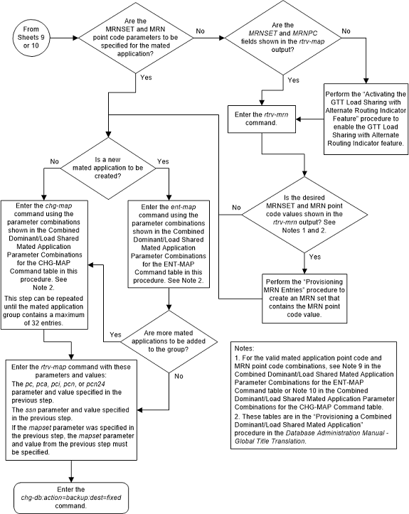
Removing a Mated Application
This procedure is used to remove a mated application from
the database using the
dlt-map command.
The
dlt-map command uses these parameters.
:pc/pca/pci/pcn/pcn24 –
The point code (primary or mate point code) in the mated application group.
Note:
Refer to Chapter 2, Configuring Destination Tables, in Database Administration - SS7 User's Guide for a definition of the point code types that are used on the EAGLE and for a definition of the different formats that can be used for ITU national point codes.:ssn – Subsystem number –
the subsystem number of the point code being removed.
:all – Removes all
subsystems assigned to the point code being removed. If this parameter is not
specified, only the specified subsystem number is removed.
:mapset – The MAP set ID
that the mated application is assigned to, shown in the
rtrv-map output. MAP set IDs are shown
only if the Flexible GTT Load Sharing feature is enabled. If the Flexible GTT
Load Sharing feature is enabled, the
mapset parameter must be specified with
the
dlt-map command.
:mrnset - The MRN set
ID assigned to the MAP set. This is the MRN set from which alternate routing
indicator searches are performed. The mrnset parameter is shown in the
rtrv-map output only if the GTT Load
Sharing with Alternate Routing Indicator feature is enabled.
If an entire MAP set is being removed in this procedure
(with the
all=yes parameter), the reference to
the MAP set specified in this procedure must be removed from any GTT, GTA, GSM
OPCODE, GSM MAP screening, or MRN entries before an entire MAP set can be
removed.
Perform one of these procedures to remove the reference to the MAP set.
- If the EGTT feature is not on – Enter the
rtrv-gttcommand to verify the MAP set ID references in the GTT entries. Perform Changing a Global Title Translation to remove the references to the MAP set. - If the EGTT feature is on – Enter the
rtrv-gtacommand to verify the MAP set ID references in the GTA entries. Perform Changing Global Title Address Information to remove the references to the MAP set. - Enter the
rtrv-gsms-opcodecommand to verify the MAP set ID references in the GSMOPCODE entries. Perform the “Changing a GSMMAP Screening Operation Code” procedure in Database Administration - Features User's Guide to remove the references to the MAP set. - Enter the
rtrv-gsmmap-scrncommand to verify the MAP set ID references in the GSMMAP screening entries. Perform the “Changing a GSM MAP Screening Entry” procedure in Database Administration - Features User's Guide to remove the references to the MAP set. - Enter the
rtrv-ppsoptscommand to verify that the mated application's point code (if the Flexible GTT Load Sharing feature is not enabled) or the point code and MAP set ID (if the Flexible GTT Load Sharing feature is enabled) is not shown in thertrv-ppsoptsoutput. Any references to the mated application's point code or the point code and MAP set ID in thertrv-ppsoptsoutput are removed in 15. - An entire MAP set cannot be removed if the MAP set is
assigned to an MRN set. A specific point code/SSN in a MAP set cannot be
removed if the MRN set that is assigned to the MAP set contains the point code
that is being removed from the MAP set. Verify that the MAP set is not assigned
to any MRN sets by entering the
rtrv-mrncommand.
The last entry of a MAP set, other than the default MAP
set, whose MAP set ID is referenced by a GTA entry in the GTT table cannot be
removed if the
xlat and
ri parameter values for that GTA entry
are
dpcssn and
ssn. Perform
Changing Global Title Address Information
to remove the references to the MAP set.
Note:
If weight and threshold values are assigned to a load shared or combined dominant/load shared mated application, and if by removing entries from this mated application the mated application becomes either a solitary or dominant mated application, all weight and threshold values are removed from the remaining entries in the mated application.If the
mapset=dflt and
all=yes parameters are specified with
the
dlt-map command, only the MAP group
containing the point code value specified in the
dlt-map command is removed from the
default MAP set.
The mated application must be in the database.
Either the
ssn or
all parameters can be specified with
the
dlt-map command, but not both.
If the
ssn parameter is specified, the point
code and subsystem pair must exist in the mate application entity set. The
point code and subsystem entry is then removed.
The value of the
ssn parameter must be from 2 to 255.
Removing all point codes but one from a dominant, load shared, or combined dominant/load shared mated application group creates a solitary mated application.
If the primary point code is removed from a dominant mated application group containing more than one mate point code, the mate point code with the lowest relative cost value becomes the new primary point code.
If the primary point code is removed from a load shared mated application group containing more than one mate point code, the next mate point code in the group becomes the new primary point code.
If the primary point code is removed from a combined dominant/load shared mated application group containing more than one mate point code, which mate point code, and the resulting mated application group depends on the resulting relative cost values remaining in the group.
- If the mated application group contains mate point codes with the same relative cost value as the primary point code being removed, the next point code in the group with the same relative cost value as the primary point code becomes the new primary point code, and the mated application group remains a combined dominant/load shared mated application group.
- If the relative cost values of the mate point codes in the group are different from the relative cost value as the primary point code being removed, the next point code in the group with the lowest relative cost value becomes the new primary point code, and the mated application group becomes a load shared mated application group.
- If all the mate point codes in the resulting mated application group have the same relative cost values, the first point code in the resulting group becomes the new primary point code, and the mated application group becomes a load shared mated application group.
- If the primary point code is removed, and the resulting mated application group contains one point code with one relative cost value and a point code with another relative cost value, a dominant mated application group is created. The mate point code with the lowest relative cost value becomes the new primary point code.
Mated applications that contain the EAGLE's true point
code and the subsystem number of one of the subsystems shown in
Table 2-51
cannot be removed from the database unless the subsystem has been removed from
the database. The EAGLE's true point code is shown in the
PCA,
PCI,
PCN, or
PCN24 fields of the
rtrv-sid output. The subsystem number
is shown in the
SSN field of the
rtrv-ss-appl output.
Table 2-51 Subsystem Features
| Feature | Subsystem | Feature Status | User's Guide that Contains the Procedures to Remove the Subsystem |
|---|---|---|---|
| LNP | LNP | Enabled | ELAP Administration and LNP Feature Activation |
| INP | INP | Enabled and Turned On | INP/AINPQ |
| ANSI-41 INP Query | |||
| EIR | EIR | Enabled and Turned On | EIR |
| V-Flex | V-Flex | Enabled and Turned On | V-Flex |
| ATINP | ATINPQ | Enabled | ATINP |
| ANSI41 AIQ | AIQ | Enabled | Analyzed Information Features |
Canceling the
RTRV-MAP Command
Because the
rtrv-map command used in this procedure
can output information for a long period of time, the
rtrv-map command can be canceled and
the output to the terminal stopped. There are three ways that the
rtrv-map command can be canceled.
- Press the
F9function key on the keyboard at the terminal where thertrv-mapcommand was entered. - Enter the
canc-cmdwithout thetrmparameter at the terminal where thertrv-mapcommand was entered. - Enter the
canc-cmd:trm=<xx>, where<xx>is the terminal where thertrv-mapcommand was entered, from another terminal other that the terminal where thertrv-mapcommand was entered. To enter thecanc-cmd:trm=<xx>command, the terminal must allow Security Administration commands to be entered from it and the user must be allowed to enter Security Administration commands. The terminal’s permissions can be verified with thertrv-secu-trmcommand. The user’s permissions can be verified with thertrv-userorrtrv-secu-usercommands.
For more information about the
canc-cmd command, refer to
Commands User's Guide.
Figure 2-102 Remove a Mated Application - Sheet 1 of 5
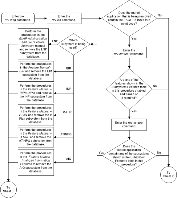
Figure 2-103 Remove a Mated Application - Sheet 2 of 5
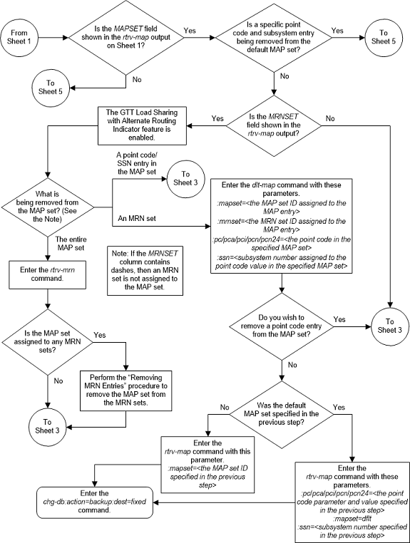
Figure 2-104 Remove a Mated Application - Sheet 3 of 5
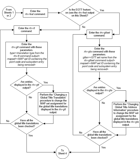
Figure 2-105 Remove a Mated Application - Sheet 4 of 5
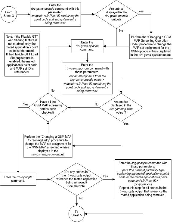
Figure 2-106 Remove a Mated Application - Sheet 5 of 5
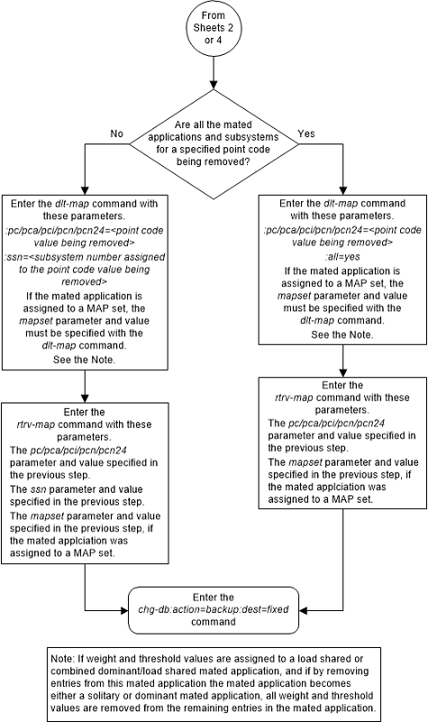
Changing the Attributes of a Mated Application
This procedure is used to change the values of the
parameters of the existing mated application (MAP) group or MAP set, shown in
Table 2-52,
using the
chg-map command.
Table 2-52 Mated Application Parameters
| CSPC group name | sso | srm | mrc | rc |
Changing the
rc value of the mated application in
this procedure is not performed to change the mated application type. If you
wish to change the mated application type, perform the
Changing the Mated Application Type
procedure.
chg-map command contains other
parameters that are not used in this procedure. Perform these procedures as
applicable to change the other parameter values.
- To change the weights or in-service thresholds of the mated application, perform the Changing the Weight and In-Service Threshold Values of a Mated Application procedure.
- To change the MRNSET and MRN point code values assigned to the mated application, perform the Changing the MRNSET and MRN Point Code Values of MAP Entries procedure.
The
chg-map command can also be used to
add point code/SSN entries to an existing MAP group or MAP set. This action is
not covered in this procedure. If you wish to add point code/SSN entries to an
existing MAP group or MAP set, perform one of these procedures.
- Provisioning a Solitary Mated Application
- Provisioning a Dominant Mated Application
- Provisioning a Load Shared Mated Application
- Provisioning a Combined Dominant/Load Shared Mated Application
The
chg-map command in this procedure uses
these parameters.
:pc/pca/pci/pcn/pcn24 –
The point code of the primary signaling point that is to receive the message.
Note:
The point codes can be either an ANSI point code (pc/pca), ITU-I or ITU-I spare point code (pci), a 14-bit ITU-N or 14-bit ITU-N spare point code (pcn), or a 24-bit ITU-N (pcn24) point code.Note:
Refer to Chapter 2, Configuring Destination Tables, in Database Administration - SS7 User's Guide for a definition of the point code types that are used on the EAGLE and for a definition of the different formats that can be used for ITU national point codes.:ssn – Subsystem number
– the subsystem address of the primary point code that is to receive the
message.
:rc – The relative cost
value of the primary point code and subsystem, defined by the
pc/pca/pci/pcn/pcn24 and
ssn parameters. The
rc parameter has a range of values
from 0 to 99.
:grp – The name of the
concerned signaling point code group that contains the point codes that should
be notified of the subsystem status. This parameter applies to both RPCs/SSNs.
:mrc – Message routing
under congestion – specifies whether Class 0 messages are routed during
congestion conditions. The values for this parameter are
yes and
no. This parameter can be specified
for any type of mated application, but this parameter affects only the traffic
for a dominant mated application.
:srm – Subsystem
routing messages – defines whether subsystem routing messages (SBR, SNR) are
transmitted between the mated applications. The values for this parameter are
yes and
no. The
srm=yes parameter can be specified
only for ANSI mated applications. This parameter affects traffic only on
dominant and combined dominant/load shared mated applications.
:sso – Subsystem Status
Option – defines whether the subsystem status option is on or off. This
parameter allows the user the option to have the specified subsystem marked as
prohibited even though an MTP-RESUME message has been received by the
indicating that the specified point code is allowed. The
sso parameter cannot be specified if
the
pc/pca/pci/pcn/pcn24 value is the
EAGLE’s true point code, shown in the
rtrv-sid output.
:mapset – The MAP set
ID that the mated applications are assigned to, shown in the
rtrv-map output. MAP set IDs are shown
only if the Flexible GTT Load Sharing feature is enabled. The
mapset parameter value cannot be
changed in this procedure. If the
rtrv-map output shows the
MAPSET field, the
mapset parameter must be specified
with the
chg-map command. If the
rtrv-map output does not show the
MAPSET field, the Flexible GTT Load
Sharing feature is not enabled. The
mapset parameter cannot be specified
with the
chg-map command. The
mapset parameter has two values.
dflt– to change the mated application in the default MAP set. The EAGLE’s true point code (shown in thertrv-sidoutput) and subsystem can be assigned only to the default MAP set.- the specific number of an existing MAP set if you are changing the mated application in an existing MAP set.
:force=yes – This
parameter must be specified if the
rc parameter is specified with either
the
srm or
mrc parameters.
At least one optional parameter must be specified.
The mated application to be changed must be in the database.
If the primary point code and subsystem are being changed, the current mated application must be removed from the database and a new mated application with the new primary point code and subsystem, containing the mated point codes and subsystems from the mated application that was removed, should be added to the database.
If the point code is entered with thepc or
pca parameters, the specified point
codes in the concerned point code broadcast group must have been entered with
the
pc or
pca parameters of the
ent-cspc command. If the point code is
entered with the
pci,pcn, or
pcn24 parameters, the specified point
codes in the concerned point code broadcast group must have been entered with
thepci,pcn,
or
pcn24 parameters of the
ent-cspc command, respectively.
If the mated application contains the EAGLE’s true point code, the relative cost value assigned to this point code must be the lowest value in the mated application.
The format of the point codes in the CSPC group
specified with the
grp parameter must be the same as the
primary point code specified with the
chg-map command only if the ANSI/ITU
SCCP Conversion feature is not enabled. If the ANSI/ITU SCCP Conversion feature
is enabled, the CSPC group may contain a mixture of point code types (refer to
the
Adding a Concerned Signaling Point Code
procedure), and the network type of the CSPC group can be different from the
network type of the primary point code of the mated application. The status of
the ANSI/ITU SCCP Conversion feature can be verified with the
rtrv-ctrl-feat command.
Canceling the
RTRV-MAP Command
Because the
rtrv-map command used in this
procedure can output information for a long period of time, the
rtrv-map command can be canceled and
the output to the terminal stopped. There are three ways that the
rtrv-map command can be canceled.
- Press the
F9function key on the keyboard at the terminal where thertrv-mapcommand was entered. - Enter the
canc-cmdwithout thetrmparameter at the terminal where thertrv-mapcommand was entered. - Enter the
canc-cmd:trm=<xx>, where<xx>is the terminal where thertrv-mapcommand was entered, from another terminal other that the terminal where thertrv-mapcommand was entered. To enter thecanc-cmd:trm=<xx>command, the terminal must allow Security Administration commands to be entered from it and the user must be allowed to enter Security Administration commands. The terminal’s permissions can be verified with thertrv-secu-trmcommand. The user’s permissions can be verified with thertrv-userorrtrv-secu-usercommands.
For more information about the
canc-cmd command, refer to
Commands User's Guide.
Figure 2-107 Change the Attributes of a Mated Application - Sheet 1 of 6
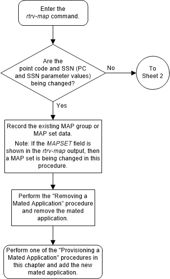
Figure 2-108 Change the Attributes of a Mated Application - Sheet 2 of 6
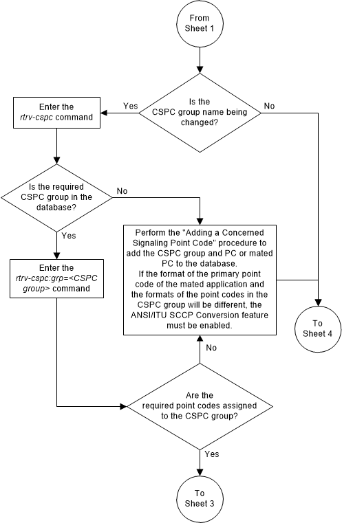
Figure 2-109 Change the Attributes of a Mated Application - Sheet 3 of 6
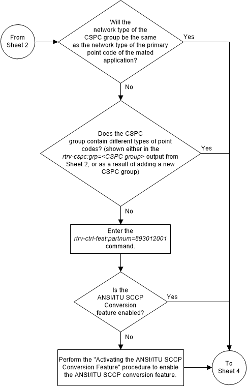
Figure 2-110 Change the Attributes of a Mated Application - Sheet 4 of 6
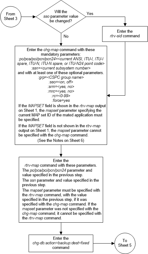
Figure 2-111 Change the Attributes of a Mated Application - Sheet 5 of 6
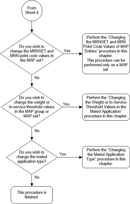
Figure 2-112 Change the Attributes of a Mated Application - Sheet 6 of 6
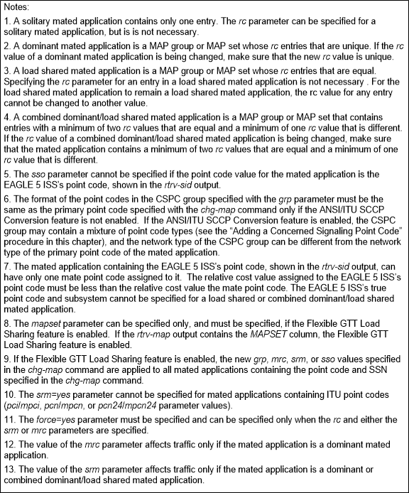
Changing the Mated Application Type
This procedure is used to change the mated application
type of an existing mated application (MAP) group or MAP set using the
chg-map command with the
rc parameter.
- Solitary - A solitary mated application contains only one entry.
- Dominant - A dominant mated application contains more than one entry and the RC (relative cost) values of these entries are unique.
- Load Shared - A load shared mated application contains more than one entry and the RC values of these entries are equal.
- Combined Dominant/Load Shared - A combined dominant/load shared mated application contains more than one entry and must contain a minimum of two entries whose RC values are equal and one entry whose RC value is different.
chg-map command contains other
parameters that are not used in this procedure. Perform these procedures as
applicable to change the other parameter values.
- To change the weights or in-service thresholds of the mated application, perform the Changing the Weight and In-Service Threshold Values of a Mated Application procedure.
- To change the MRNSET and MRN point code values assigned to the mated application, perform the Changing the MRNSET and MRN Point Code Values of MAP Entries procedure.
- To change other attributes of the mated application, perform the Changing the Attributes of a Mated Application procedure.
chg-map command can also be used to
add point code/SSN entries to an existing MAP group or MAP set. This action is
not covered in this procedure. If you wish to add point code/SSN entries to an
existing MAP group or MAP set, perform one of these procedures.
The
chg-map command in this procedure uses
these parameters.
:pc/pca/pci/pcn/pcn24 –
The point code of the primary signaling point that is to receive the message.
Note:
The point codes can be either an ANSI point code (pc/pca), ITU-I or ITU-I spare point code (pci), a 14-bit ITU-N or 14-bit ITU-N spare point code (pcn), or a 24-bit ITU-N (pcn24) point code.Note:
Refer to Chapter 2, Configuring Destination Tables, in the Database Administration - SS7 User's Guide for a definition of the point code types that are used on the EAGLE and for a definition of the different formats that can be used for ITU national point codes.:ssn – Subsystem number
– the subsystem address of the primary point code that is to receive the
message.
:rc – The relative cost
value of the primary point code and subsystem, defined by the
pc/pca/pci/pcn/pcn24 and
ssn parameters. The
rc parameter has a range of values
from 0 to 99.
:mapset – The MAP set
ID that the mated applications are assigned to, shown in the
rtrv-map output. MAP set IDs are shown
only if the Flexible GTT Load Sharing feature is enabled. The
mapset parameter value cannot be
changed in this procedure. If the
rtrv-map output shows the
MAPSET field, the
mapset parameter must be specified
with the
chg-map command. If the
rtrv-map output does not show the
MAPSET field, the Flexible GTT Load
Sharing feature is not enabled. The
mapset parameter cannot be specified
with the
chg-map command. The
mapset parameter has two values.
dflt– to change the mated application in the default MAP set. The EAGLE’s true point code (shown in thertrv-sidoutput) and subsystem can be assigned only to the default MAP set.- the specific number of an existing MAP set if you are changing the mated application in an existing MAP set.
The mated application to be changed must be in the database.
If an existing dominant, load shared, or combined dominant/load shared mated application is being changed to a solitary mated application, the existing mated application must be removed from the database, and the new solitary mated application, containing the primary point code and subsystem from the mated application that was removed, must be added to the database.
If the mated application contains the EAGLE’s true point code, the relative cost value assigned to this point code must be the lowest value in the mated application.
Canceling the
RTRV-MAP Command
Because the
rtrv-map command used in this
procedure can output information for a long period of time, the
rtrv-map command can be canceled and
the output to the terminal stopped. There are three ways that the
rtrv-map command can be canceled.
- Press the
F9function key on the keyboard at the terminal where thertrv-mapcommand was entered. - Enter the
canc-cmdwithout thetrmparameter at the terminal where thertrv-mapcommand was entered. - Enter the
canc-cmd:trm=<xx>, where<xx>is the terminal where thertrv-mapcommand was entered, from another terminal other that the terminal where thertrv-mapcommand was entered. To enter thecanc-cmd:trm=<xx>command, the terminal must allow Security Administration commands to be entered from it and the user must be allowed to enter Security Administration commands. The terminal’s permissions can be verified with thertrv-secu-trmcommand. The user’s permissions can be verified with thertrv-userorrtrv-secu-usercommands.
For more information about the
canc-cmd command, refer to
Commands User's Guide.
Figure 2-113 Change the Mated Application Type - Sheet 1 of 6
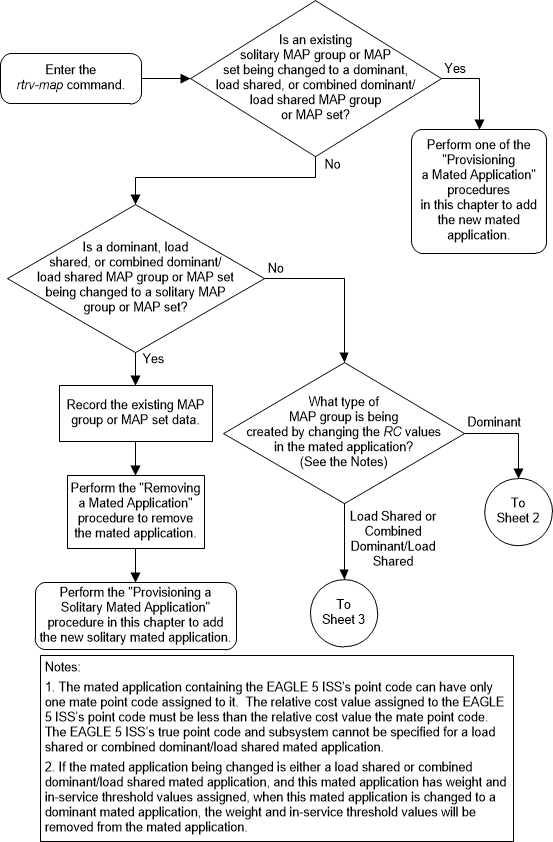
Figure 2-114 Change the Mated Application Type - Sheet 2 of 6
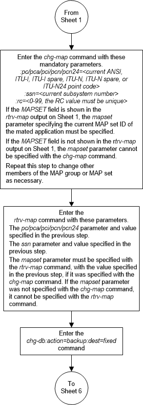
Figure 2-115 Change the Mated Application Type - Sheet 3 of 6
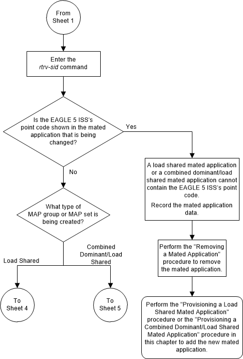
Figure 2-116 Change the Mated Application Type - Sheet 4 of 6
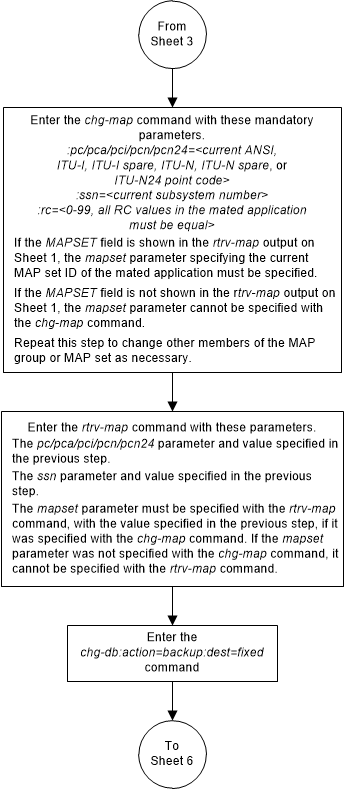
Figure 2-117 Change the Mated Application Type - Sheet 5 of 6
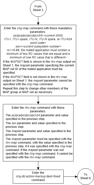
Figure 2-118 Change the Mated Application Type - Sheet 6 of 6
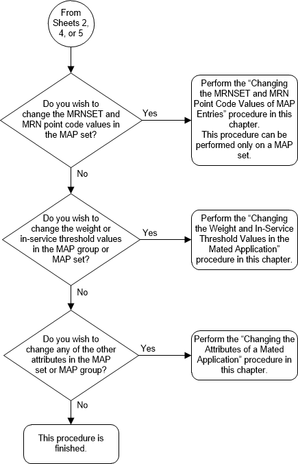
Changing the Weight and In-Service Threshold Values of a Mated Application
This procedure is used to change the weight and
in-service threshold values, for the Weighted GTT Load Sharing feature, that
are assigned to the entries in an existing mated application (MAP) group or MAP
set using the
chg-map command with the parameters
shown in
Table 2-53.
Table 2-53 Mated Application Weight and In-Service Threshold Parameters
| wt | eswt | grpwt | thr |
The
eswt,
grpwt,
wt, and
thr parameters can be used only if the
MAP group or MAP set is either a load shared or combined dominant/load shared
MAP group or MAP set, and the Weighted GTT Load Sharing feature is enabled and
turned on.
A load shared mated application contains more than one entry and the RC values of these entries are equal. A combined dominant/load shared mated application contains more than one entry and must contain a minimum of two entries whose RC values are equal and one entry whose RC value is different.
The status of the Weighted GTT Load Sharing feature can
be verified by entering the
rtrv-ctrl-feat command. If the
Weighted GTT Load Sharing feature is not enabled or not turned on, perform the
Activating the Weighted GTT Load Sharing Feature
procedure to enable and turn on the Weighted GTT Load Sharing feature.
The
rc parameter can also be specified in
this procedure. Changing the
rc value of the mated application in
this procedure is not performed to change the mated application type. If you
wish to change the mated application type, perform the
Changing the Mated Application Type
procedure.
chg-map command contains other
parameters that are not used in this procedure. Perform these procedures as
applicable to change the other parameter values.
- To change the MRNSET and MRN point code values assigned to the mated application, perform the Changing the MRNSET and MRN Point Code Values of MAP Entries procedure.
- To change other attributes of the mated application, perform the Changing the Attributes of a Mated Application procedure.
chg-map command can also be used to
add point code/SSN entries to an existing MAP group or MAP set. This action is
not covered in this procedure. If you wish to add point code/SSN entries to an
existing MAP group or MAP set, perform one of these procedures.
The
chg-map command uses these parameters.
:pc/pca/pci/pcn/pcn24 –
The point code of the primary signaling point that is to receive the message.
Note:
The point codes can be either an ANSI point code (pc/pca, mpc/mpca), ITU-I or ITU-I spare point code (pci, mpci), a 14-bit ITU-N or 14-bit ITU-N spare point code (pcn, mpcn), or a 24-bit ITU-N (pcn24,
mpcn24) point code.
Note:
Refer to Chapter 2, Configuring Destination Tables, in Database Administration - SS7 User's Guide for a definition of the point code types that are used on the EAGLE and for a definition of the different formats that can be used for ITU national point codes.:ssn – Subsystem number
– the subsystem address of the primary point code that is to receive the
message.
:rc – The relative cost
value of the primary point code and subsystem, defined by the
pc/pca/pci/pcn/pcn24 and
ssn parameters. The
rc parameter has a range of values
from 0 to 99.
:mapset – The MAP set
ID that the mated applications are assigned to, shown in the
rtrv-map output. MAP set IDs are shown
only if the Flexible GTT Load Sharing feature is enabled. The
mapset parameter value cannot be
changed in this procedure. If the
rtrv-map output shows the
MAPSET field, the
mapset parameter must be specified
with the
chg-map command. If the
rtrv-map output does not show the
MAPSET field, the Flexible GTT Load
Sharing feature is not enabled. The
mapset parameter cannot be specified
with the
chg-map command. The
mapset parameter has two values.
dflt– to change the mated application in the default MAP set. The EAGLE’s true point code (shown in thertrv-sidoutput) and subsystem can be assigned only to the default MAP set.- the specific number of an existing MAP set if you are changing the mated application in an existing MAP set.
:eswt – The entity set
weight value. When this parameter is specified, the same weight value is
assigned to all entries in the MAP group or MAP set that contain the point code
value specified in the
chg-map command. A MAP group or MAP
set can also be referred to as an entity set. The value of this parameter is
from 1 - 99.
:grpwt – The group
weight value. When this parameter is specified, the same weight value is
assigned to all entries that have the same RC (relative cost) value in the MAP
group or MAP set that contain the point code specified in the
chg-map command. The value of this
parameter is from 1 - 99.
Note:
Specifying thegrpwt parameter for a load shared
mated application has the same effect as specifying the
eswt parameter for a load shared
mated application as all the entries in a load shared mated application have
the same RC value.
:wt – The weight value
assigned to a specific point code and SSN entry in the mated application. The
value of this parameter is from 1 - 99. This parameter allows for each entry in
the mated application to have a different weight value.
:thr – The in-service
threshold assigned to the MAP group or MAP set. The in-service threshold is the
minimum percentage (from 1 - 100) of weight that must be available for an RC
group (a group of entries in the MAP group or MAP set that have the same RC
value assigned) to be considered available to carry traffic. If the percentage
of the available weight is less than the in-service threshold, then the entire
RC group is considered unavailable for traffic. If the percentage of the
available weight is equal to or greater than the in-service threshold, then the
RC group is considered available, and traffic can be sent to any available
entity in the RC group. When the
thr parameter is specified with the
eswt parameter, the in-service
threshold value is assigned to all the entries of the MAP group or MAP set.
When the
thr parameter is specified with the
grpwt parameter, or without either the
eswt or
grpwt parameters, the in-service
threshold value is assigned to all the entries of the MAP group or MAP set that
have the same RC value as the point code specified with the
chg-map command.
:force=yes – This
parameter must be specified if the
rc parameter is specified with the
wt parameter.
Weighted GTT Load Sharing allows unequal traffic loads to be provisioned in MAP load sharing groups or MAP load sharing sets. This feature also allows provisioning control over load sharing groups or sets so that if insufficient capacity within the load sharing group or set is available, the load sharing group or set is not used.
The weight and in-service threshold values for a mated
application are shown in the
rtrv-map output. The weight values
assigned to the entires in the MAP group or MAP set are shown in the
WT column in the
rtrv-map output.
The
%WT column in the
rtrv-map output shows the percentage
of the traffic the particular entry in the entity set will handle.
The in-service threshold values assigned to the entires
in the MAP group or MAP set are shown in the
THR column in the
rtrv-map output.
The
WT,
%WT, and
THR columns are shown in the
rtrv-map output only if the Weighted
GTT Load Sharing feature is enabled and turned on.
For more information on the Weighted GTT Load Sharing feature, refer to the Weighted GTT Load Sharing section.
The mated application to be changed must be in the database.
Canceling the
RTRV-MAP Command
Because the
rtrv-map command used in this
procedure can output information for a long period of time, the
rtrv-map command can be canceled and
the output to the terminal stopped. There are three ways that the
rtrv-map command can be canceled.
- Press the
F9function key on the keyboard at the terminal where thertrv-mapcommand was entered. - Enter the
canc-cmdwithout thetrmparameter at the terminal where thertrv-mapcommand was entered. - Enter the
canc-cmd:trm=<xx>, where<xx>is the terminal where thertrv-mapcommand was entered, from another terminal other that the terminal where thertrv-mapcommand was entered. To enter thecanc-cmd:trm=<xx>command, the terminal must allow Security Administration commands to be entered from it and the user must be allowed to enter Security Administration commands. The terminal’s permissions can be verified with thertrv-secu-trmcommand. The user’s permissions can be verified with thertrv-userorrtrv-secu-usercommands.
For more information about the
canc-cmd command, refer to
Commands User's Guide.
Figure 2-119 Change the Weight and In-Service Threshold Values of a Mated Application - Sheet 1 of 8
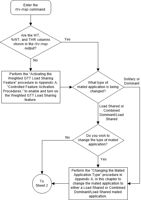
Figure 2-120 Change the Weight and In-Service Threshold Values of a Mated Application - Sheet 2 of 8
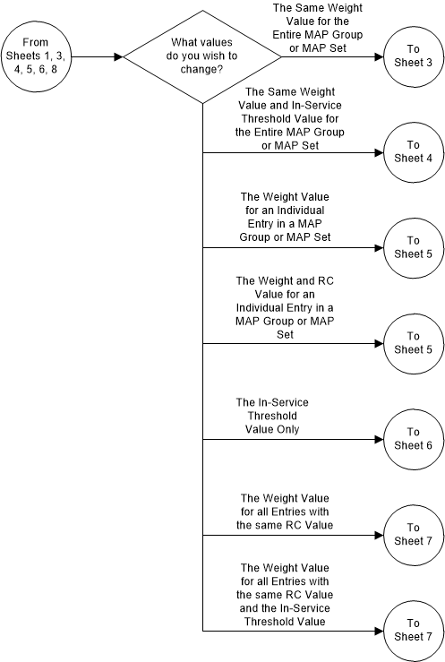
Figure 2-121 Change the Weight and In-Service Threshold Values of a Mated Application - Sheet 3 of 8
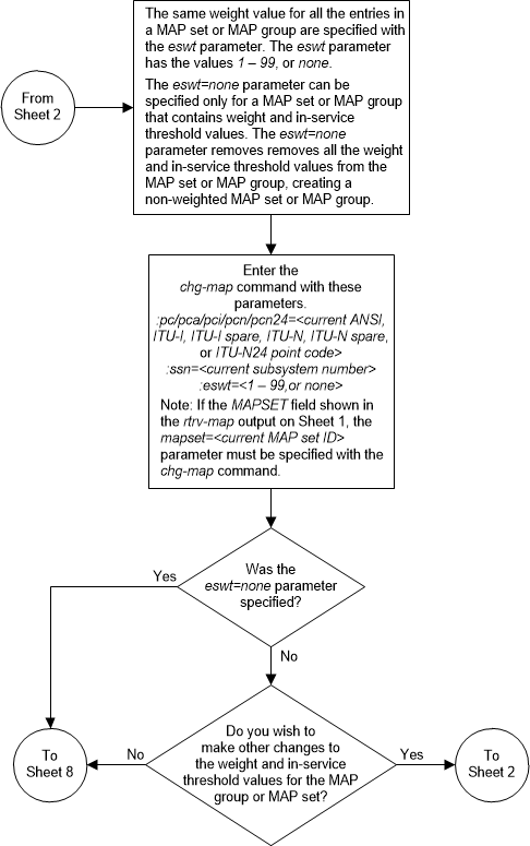
Figure 2-122 Change the Weight and In-Service Threshold Values of a Mated Application - Sheet 4 of 8
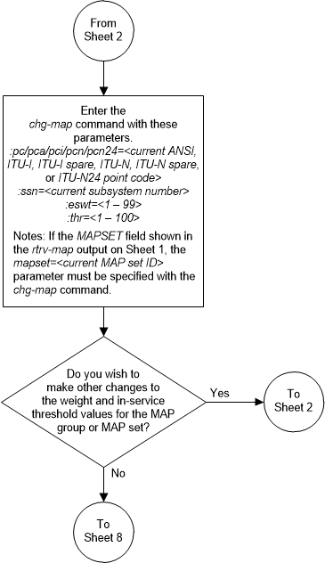
Figure 2-123 Change the Weight and In-Service Threshold Values of a Mated Application - Sheet 5 of 8
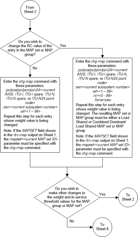
Figure 2-124 Change the Weight and In-Service Threshold Values of a Mated Application - Sheet 6 of 8
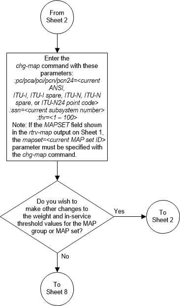
Figure 2-125 Change the Weight and In-Service Threshold Values of a Mated Application - Sheet 7 of 8
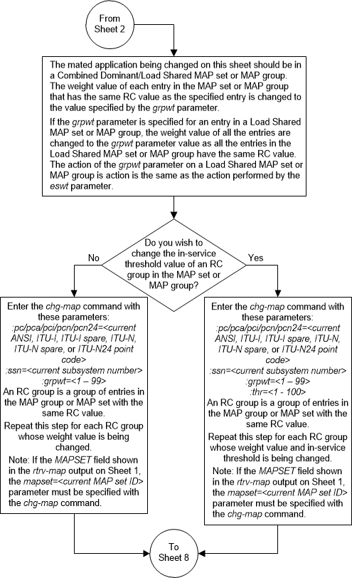
Figure 2-126 Change the Weight and In-Service Threshold Values of a Mated Application - Sheet 8 of 8
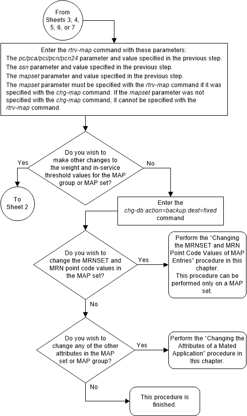
Changing the MRNSET and MRN Point Code Values of MAP Entries
This procedure is used to change the MRNSET and MRN
point code values in an existing mated application (MAP) set using the
mrnsetand
mrnpc/mrnpca/mrnpci/
mrnpcn/mrnpcn24 parameters of the
chg-map command.
chg-map command can also be used to
add point code/SSN entries to an existing MAP set. This action is not covered
in this procedure. If you wish to add point code/SSN entries to an existing MAP
set, perform one of these procedures.
- To change the mated application type of the mated application, perform the Changing the Mated Application Type procedure.
- To change the weights or in-service thresholds of the mated application, perform the Changing the Weight and In-Service Threshold Values of a Mated Application procedure.
- To change other attributes of the mated application, perform the Changing the Attributes of a Mated Application procedure.
These parameters are used with the
chg-map command in this procedure.
:mapset – The MAP set
ID that is being changed.
:pc/pca/pci/pcn/pcn24 –
The point code in the MAP set.
:ssn – The subsystem
number assigned to the point code in the MAP set.
:mrnset – The MRN set
ID that is being assigned to the mated application. This is the MRN set from
which alternate routing indicator searches are performed.
:mrnpc/mrnpca/mrnpci/mrnpcn/mrnpcn24 – The point code
assigned to the
mrnset that is being assigned to the
MAP set.
Note:
Refer to Chapter 2, Configuring Destination Tables in Database Administration - SS7 User's Guide for a definition of the point code types that are used on the EAGLE and for a definition of the different formats that can be used for ITU national point codes.The current values of the
mrnset and
:mrnpc/mrnpca/mrnpci/mrnpcn/mrnpcn24
parameters are shown in the
rtrv-map output only if the Flexible
GTT Load Sharing and the GTT Load Sharing with Alternate Routing Indicator
features are enabled.
The new values for the
mrnset and
mrnpc/mrnpca/mrnpci/mrnpcn/mrnpcn24
parameters must be shown in the
rtrv-mrn output.
The network type of the
pc/pca/pci/pcn/pcn24 and
mrnpc/mrnpca/mrnpci/mrnpcn/mrnpcn24
parameter values must be compatible, as shown in
Table 2-54.
Table 2-54 MAP and MRN Point Code Parameter Combinations
| MAP Point Code Parameter | MRN Point Code Parameter |
|---|---|
| pc/pca | mrnpc/mrnpca |
| pci or pcn (See Notes 1 and 2) | mrnpci or mrnpcn (See Notes 1 and 2) |
| pcn24 | mrnpcn24 |
|
Notes: 1. If the network type of the MAP point code parameter is
ITU-I ( 2. If the network type of the MAP point code parameter is
ITU-N ( |
|
Canceling the
RTRV-MAP Command
Because the
rtrv-map command used in this
procedure can output information for a long period of time, the
rtrv-map command can be canceled and
the output to the terminal stopped. There are three ways that the
rtrv-map command can be canceled.
- Press the
F9function key on the keyboard at the terminal where thertrv-mapcommand was entered. - Enter the
canc-cmdwithout thetrmparameter at the terminal where thertrv-mapcommand was entered. - Enter the
canc-cmd:trm=<xx>, where<xx>is the terminal where thertrv-mapcommand was entered, from another terminal other that the terminal where thertrv-mapcommand was entered. To enter thecanc-cmd:trm=<xx>command, the terminal must allow Security Administration commands to be entered from it and the user must be allowed to enter Security Administration commands. The terminal’s permissions can be verified with thertrv-secu-trmcommand. The user’s permissions can be verified with thertrv-userorrtrv-secu-usercommands.
For more information about the
canc-cmd command, refer to
Commands User's Guide.
Figure 2-127 Change the MRNSET and MRN Point Code Values of MAP Entries - Sheet 1 of 3
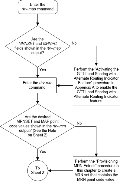
Figure 2-128 Change the MRNSET and MRN Point Code Values of MAP Entries - Sheet 2 of 3
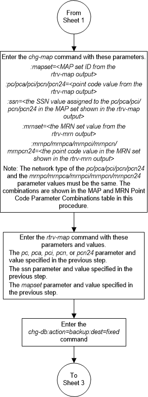
Figure 2-129 Change the MRNSET and MRN Point Code Values of MAP Entries - Sheet 3 of 3
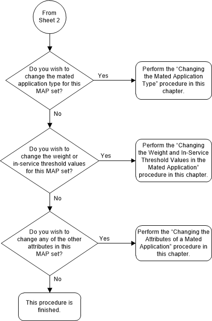
Provisioning MRN Entries
This procedure is used to provision an Mated Relay Node
(MRN) group or MRN set in the database or to add a point code to an existing
MRN group or MRN set for the Intermediate Global Title Load Sharing feature
using the
ent-mrn and
chg-mrn commands.
An MRN group or MRN set contains alternate point codes, up to 128, that are used for load sharing between multiple nodes when the EAGLE is performing intermediate global title translation. This load sharing is performed after intermediate global title translation is performed on the message. The point code in the message is changed to the selected point code in the MRN table. If the translated point code is not found in the MRN table, the translated point code in the message is not changed, the message is routed using route for the translated point code.
The
ent-mrn and
chg-mrn command uses these parameters.
:pc/pca/pci/pcn/pcn24 –
The point code in the message after intermediate global title translation has
been performed.
:rc – The relative cost
value of point code in the message
:pc1/pca1/pci1/pcn1/pcn241 – The first alternate point
code value
:rc1 – The relative
cost value of the first alternate point code
:pc2/pca2/pci2/pcn2pcn242 – The second alternate point
code value
:rc2 – The relative
cost value of the second alternate point code
:pc3/pca3/pci3/pcn3/pcn243 – The third alternate point
code value
:rc3 – The relative
cost value of the third alternate point code
:pc4/pca4/pci4/pcn4/pcn244 – The fourth alternate point
code value
:rc4 – The relative
cost value of the fourth alternate point code
Note:
Refer to Chapter 2, Configuring Destination Tables in Database Administration - SS7 User's Guide for a definition of the point code types that are used on the EAGLE and for a definition of the different formats that can be used for ITU national point codes.:mrnset – The MRN set
ID that the point codes are assigned to. This parameter can be specified only,
and must be specified, if the Flexible GTT Load Sharing feature is enabled. If
the Flexible GTT Load Sharing feature is enabled, the point code specified for
the global title translation must be assigned to the MRN set specified by this
parameter. The status of the Flexible GTT Load Sharing feature is shown in the
rtrv-ctrl-feat output. To enable the
Flexible GTT Load Sharing feature, perform
Activating the Flexible GTT Load Sharing Feature.
The MRN set ID has one of three values:
dflt– to assign the MRN to the default MRN set.new– to assign the MRN to a new MRN set. This value can be specified only with theent-mrncommand.- the specific number of an existing MRN set if you are
assigning the point codes to an existing MRN set.
Refer to Provisioning an MRN Set for information on provisioning MRN sets.
:dfltwt – The default
weight value. When this parameter is specified, the same weight value is
assigned to all entries specified in the
ent-mrn command. The value of this
parameter is from 1 - 99. This parameter can be specified only with the
ent-mrn command.
:wt – The weight value
assigned to the
pc/pca/pci/pcn/pcn24 parameter
value. The value of this parameter is from 1 - 99.
:wt1 – The weight value
assigned to the
pc1/pca1/pci1/pcn1/pcn241 parameter
value. The value of this parameter is from 1 - 99.
:wt2 – The weight value
assigned to the
pc2/pca2/pci2/pcn2/pcn242 parameter
value. The value of this parameter is from 1 - 99.
:wt3 – The weight value
assigned to the
pc3/pca3/pci3/pcn3/pcn243 parameter
value. The value of this parameter is from 1 - 99.
:wt4 – The weight value
assigned to the
pc4/pca4/pci4/pcn4/pcn244 parameter
value.
:thr – The in-service
threshold assigned to the MRN group or MRN set. The in-service threshold is the
minimum percentage (from 1 - 100) of weight that must be available for an RC
group (a group of entries in the MRN group or MRN set that have the same RC
value assigned) to be considered available to carry traffic. If the percentage
of the available weight is less than the in-service threshold, then the entire
RC group is considered unavailable for traffic. If the percentage of the
available weight is equal to or greater than the in-service threshold, then the
RC group is considered available, and traffic can be sent to any available
entity in the RC group. The value of the
thr parameter is assigned to all
entries in the MRN group or MRN set that have the same RC value that is
specified in the
ent-mrn command. The
thr parameter can be used in this
procedure only with the
ent-mrn command.
Refer to Provisioning Weights and In-Service Thresholds for MRNs for information on provisioning MRN groups or MRN sets with weight and in-service threshold values.
The following parameters of the
chg-mrn command cannot be used in this
procedure:
thr,
grpwt,
eswt, and
force=yes. These parameters can be
used with the
chg-mrn command only when changing the
attributes of specific entries in an existing MRN group or MRN set, and not
when adding entries to an existing MRN group or MRN set. If you wish to change
specific entries in an existing MRN group or MRN set, perform either
Changing MRN Entries with the ESWT Parameter
or
Changing the Weight and Threshold Values of MRN Entries.
:mapset – The MAP set
ID that is being assigned to the MRN. This is the MAP set from which alternate
routing indicator searches are performed.
:mappc/mappca/mappci/mappcn/mappcn24 – The point code
assigned to the
mapset that is being assigned to the
MRN set.
:mapssn – The subsystem
number assigned to the point code in the MAP set that is being assigned to the
MRN.
The current values of the
mapset,
mappc/mappca/mappci/mappcn/mappcn24,
and
mapssn parameters are shown in the
rtrv-mrn output only if the Flexible
GTT Load Sharing and the GTT Load Sharing with Alternate Routing Indicator
features are enabled.
The new values for the
mapset,
mappc/mappca/mappci/mappcn/mappcn24,
and
mapssn parameters must be shown in the
rtrv-map output. If no values are
specified for the
mapset,
mappc/mappca/mappci/mappcn/mappcn24,
and
mapssn parameters when the
ent-mrn command is entered, then no
values for these parameters are assigned to the MRN set. If no values are
specified for the
mapset,
mappc/mappca/mappci/mappcn/mappcn24,
and
mapssn parameters when the
chg-mrn command is entered, then the
values for these parameters in the MRN set are not changed.
To add a new MRN group, the group must be provisioned in
the database with the
ent-mrn command, specifying up to four
alternate point codes. If more point codes are to be added to the MRN group,
either the
ent-mrn or
chg-mrn command to add the additional
point codes to the MRN group. A maximum of 128 point codes can be assigned to
an MRN group. If the Flexible GTT Load Sharing feature is enabled, refer to
Provisioning
an MRN Set for information on provisioning MRN sets.
A point code and
rc value must be entered as a pair.
For example, the
pc3 and
rc3 parameters must be specified
together in the
ent-mrn or
chg-mrn commands if the alternate
point code value is being specified.
The point codes specified with the
ent-mrn or
chg-mrn commands can be in only one
MRN group. If the Flexible GTT Load Sharing feature is enabled, refer to
Provisioning
an MRN Set for information on provisioning point codes in MRN sets.
The relative cost parameters (rc/rc1/rc2/rc3/rc4) determine how the global title translation load is
to be shared among the alternate point codes. There are three types of load
sharing that can be performed: dominant, load shared, or combined dominant/load
shared.
All the point codes in a dominant MRN group or MRN set have different relative cost values. The translated point code in the message is the preferred point code that the message is routed on. The relative cost value assigned to the preferred point code does not have to be the lowest value in the MRN group or MRN set. All traffic is routed to the preferred point code, if it is available. If the preferred point code becomes unavailable, the traffic is routed to highest priority alternate point code that is available. When the preferred point code becomes available again, the traffic is then routed back to the preferred point code. For example, the MRN table contains the following entries.
PC RC
005-005-005 10
006-001-001 20
006-001-002 30
006-001-003 40
006-001-004 50
006-001-005 60
006-001-006 70
006-001-007 80If the preferred point code is 006-001-001 and it becomes unavailable, the traffic will be routed to point code 006-001-002.
All the point codes in a load shared MRN group or MRN set have the same relative cost value. Traffic is shared equally between the point codes in this MRN group or MRN set.
A combined dominant/load shared MRN group or MRN set is a combination of the dominant and load sharing MRN groups or MRN sets. A combined dominant/load shared MRN group or MRN set must contain a minimum of two entries with the same relative cost value and a minimum of one entry with a different relative cost value. Traffic is routed to the point code or point codes with the lowest relative cost value, where the relative cost value is considered the relative cost associated with the point code of the global title translation and not the actual lowest relative cost in the MRN set. If more than one point code has the lowest relative cost value, the traffic is shared between these point codes. If the point code or point codes with the lowest relative cost value become unavailable, traffic is routed to the point code or point codes with the next higher relative cost value. If more than one point code has this relative cost value, the traffic is shared between these point codes. For example, the MRN table contains the following entries.
PC RC
005-005-005 10
006-001-001 10
006-001-002 10
006-001-003 20
006-001-004 20
006-001-005 20
006-001-006 20
006-001-007 20If the preferred point code is 006-001-001, the traffic is shared equally between point codes 005-005-005, 006-001-001, and 006-001-002. If point codes 005-005-005, 006-001-001, and 006-001-002 become unavailable, the traffic will be shared equally between point codes, 006-001-003, 006-001-004, 006-001-005, 006-001-006, and 006-001-007.
The point codes in the MRN group or MRN set must be a
full point code with a route assigned to it. Cluster point codes, network
routing point codes, or the EAGLE’s true point code cannot be specified in an
MRN group or MRN set. The
rtrv-rte command can be used to verify
the point codes in the routing table. The point codes in the routing table are
shown in the
DPCA,
DPCI,
DPCN, or
DPCN24 fields of the
rtrv-rte command output. The EAGLE’s
true point code is shown in the
PCA,
PCI,
PCN, or
PCN24 fields of the
rtrv-sid command output.
The Intermediate GTT Load Sharing controlled feature
must be enabled and activated before an MRN group can be provisioned in the
database. This can be verified with the
rtrv-ctrl-feat command. If this
controlled feature is enabled and activated, the Intermediate GTT Load Sharing
feature is shown as either temporarily or permanently enabled in the
rtrv-ctrl-feat output, and the entry
on is shown in the
Status column for this feature. If
this controlled feature is off, perform
Activating the IGTTLS feature
to enable and turn on this feature.
For MRNs containing ANSI or 24-bit ITU-N point codes,
the format of the point codes specified in the
ent-mrn command must be the same. For
example, if the primary point code is a 24-bit ITU-N point code (pcn24), the alternate point code must be a 24-bit ITU-N
point code (mpcn24). The alternate point codes
of MRNs containing either ITU-I, ITU-I spare, 14-bit ITU-N, or 14-bit ITU-N
spare primary point codes do not have to be the same format as the primary
point code. The alternate point codes of these MRNs can be a mixture of ITU-I,
ITU-I spare, 14-bit ITU-N, or 14-bit ITU-N spare point codes.
If only the Intermediate GTT Load Sharing feature is
enabled and turned on, the MRN table can contain a maximum of 3000 entries. If
the Flexible GTT Load Sharing feature is enabled, the MRN table can contain a
maximum of 6000 entries. If entries are provisioned in the SCCP-SERV table,
shown by the
rtrv-sccp-serv command output, the
maximum number of entries that the MRN table can contain is reduced by the
number of entries shown in the
rtrv-sccp-serv command output.
If adding the new MRN entries will exceed the maximum
capacity of the MRN table, shown in the
rtrv-mrn command output, entries in
the MRN or SCCP-SERV tables must be removed so that the new MRN entries can be
added. Perform
Removing MRN Entries
to remove the required number of MRN entries to allow the addition of the new
MRN entries or enter the
dlt-sccp-serv command to remove the
required number of entries in the SCCP-SERV table to allow the addition of the
new MRN entries.
Provisioning an MRN Set
The Flexible GTT Load Sharing feature provides the ability to define multiple load sharing sets in the MRN table where the same point code can be assigned to different load sharing sets.
TheMRN table contains specific load sharing sets, designated by numbers, and a default MRN set.
The MRN table without the Flexible GTT Load Sharing feature enabled, is used by MPS based features and all global title translation features.
The Flexible GTT Load Sharing feature provides flexible load sharing for global title translations defined in the GTT table and not for the MPS based features. The MPS based features do not support the MRN set ID parameter. The MPS based features perform lookups for load sharing in the default MRN set and the GTT table. The entries in the GTT table can be linked to an MRN set ID, allowing lookups in a specific MRN set other than the default MRN set.
Any MRN entries that were provisioned in the database before the Flexible GTT Load Sharing feature is enabled are placed in the default MRN set when the Flexible GTT Load Sharing feature is enabled.
Any GTT entries that were provisioned in the database before the Flexible GTT Load Sharing feature is enabled are assigned to the default MRN set when the Flexible GTT Load Sharing feature is enabled.
If the Flexible GTT Load Sharing is enabled, the
mrnset parameter must be specified
with the
ent-mrn or
chg-mrn commands.
To provision entries in the default MRN set, the
mrnset=dflt parameter must be
specified with the
ent-mrn or
chg-mrn commands.
To provision entries in an existing MRN set other than
the default MRN set, the
mrnset=<MRN set ID> parameter
must be specified with the
ent-mrn or
chg-mrn commands. The
rc parameter value for this point
code should not be specified. If the
rc parameter is specified, an
attempt will be made to provision another MRN group in this MRN set. Multiple
MRN groups in one MRN set is supported only in the default MRN set. The new
entries to this MRN set must be specified with the alternate point code
parameters and their corresponding
rc parameters.
To provision entries in a new MRN set, the
mrnset=new parameter must be specified
with the
ent-mrn command. The
mrnset=new parameter can be specified
only with the
ent-mrn command. When the
ent-mrn command is executed with the
mrnset=new parameter, the new MRN set
ID is automatically generated and displayed in the output of the
ent-mrn command as follows.
New MRNSET Created : MRNSETID = <new MRN set ID>An MRN set, other than the default MRN set, is an MRN group provisioned with the MRN set ID and can contain a maximum of 128 point codes.
The default MRN set can contain multiple MRN groups. Each group in the default MRN set can contain a maximum of 128 point codes. The point code value can appear only once in the default MRN set, so the point code value can appear in only one MRN group in the default MRN set.
The point code provisioned in an MRN set can be provisioned in multiple MRN sets. All the point codes in an MRN set must be different.
Provisioning Weights and In-Service Thresholds for MRN Entries
Weighted GTT Load Sharing allows unequal traffic loads to be provisioned in load sharing groups. This feature also allows provisioning control over load sharing groups so that if insufficient capacity within the load sharing group is available, the load sharing group is not used.
To provision the weight values and in-service threshold
values for new MRN groups or MRN sets or new entries in existing MRN groups or
MRN sets, the
dfltwt,
wt,
wt1,
wt2,
wt3,
wt4, and
thr parameters are used.
The
dfltwt,
wt,
wt1,
wt2,
wt3,
wt4, and
thr parameters can be used only:
- If the MRN group or MRN set is either a load shared or combined dominant/load shared MRN group or MRN set.
- If the Weighted GTT Load Sharing feature is enabled and turned on.
The status of the Weighted GTT Load Sharing feature can
be verified by entering the
rtrv-ctrl-feat command. If the
Weighted GTT Load Sharing feature is not enabled or not turned on, perform
Activating the Weighted GTT Load Sharing Feature
to enable and turn on the Weighted GTT Load Sharing feature.
To assign the same weight value to all the entries
specified in the
ent-mrn command, use the
dfltwt parameter.
To assign an in-service threshold value to all the
entries specified in the
ent-mrn command, use the
thr parameter.
To assign different weight values to the entries
specified in either the
ent-mrn or
chg-mrn commands, use the
wt,
wt1,
wt2,
wt3, and
wt4 parameters with the corresponding
point code parameters.
The
dfltwt parameter and the individual
weight parameters (wt,
wt1,
wt2,
wt3,
wt4 parameters) cannot be specified
together in the
ent-mrn command.
The
thr parameter cannot be specified in
this procedure with the
chg-mrn command. Specifying the
thr parameter with the
chg-mrn command can be done when
specifying only the
pc/pca/pci/pcn/pcn24 parameter
and without the alternate point code parameters. To specify the
thr parameter with the
chg-mrn command, perform either
Changing MRN Entries with the ESWT Parameter
or
Changing the Weight and Threshold Values of MRN Entries.
The weight values assigned to the entries in the MRN
group or MRN set are shown in the
WT column in the
rtrv-mrn output.
The in-service threshold values assigned to the entries
in the MRN group or MRN set are shown in the
THR column in the
rtrv-mrn output.
The
%WT column in the
rtrv-mrn output shows the percentage
of the traffic the particular entry in the entity set will handle.
The
WT,
%WT, and
THR columns are shown in the
rtrv-mrn output only if the Weighted
GTT Load Sharing feature is enabled and turned on.
For more information on the Weighted GTT Load Sharing feature, refer to the Weighted GTT Load Sharing section.
Canceling the
RTRV-MRN Command
Because the
rtrv-mrn command used in this
procedure can output information for a long period of time, the
rtrv-mrn command can be canceled and
the output to the terminal stopped. There are three ways that the
rtrv-mrn command can be canceled.
- Press the
F9function key on the keyboard at the terminal where thertrv-mrncommand was entered. - Enter the
canc-cmdwithout thetrmparameter at the terminal where thertrv-mrncommand was entered. - Enter the
canc-cmd:trm=<xx>, where<xx>is the terminal where thertrv-mrncommand was entered, from another terminal other that the terminal where thertrv-mrncommand was entered. To enter thecanc-cmd:trm=<xx>command, the terminal must allow Security Administration commands to be entered from it and the user must be allowed to enter Security Administration commands. The terminal’s permissions can be verified with thertrv-secu-trmcommand. The user’s permissions can be verified with thertrv-userorrtrv-secu-usercommands.
For more information about the
canc-cmd command, refer to
Commands User's Guide.
Figure 2-130 Provision MRN Entries - Sheet 1 of 5
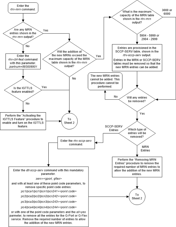
Figure 2-131 Provision MRN Entries - Sheet 2 of 5
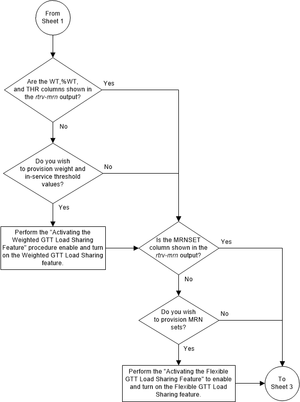
Figure 2-132 Provision MRN Entries - Sheet 3 of 5
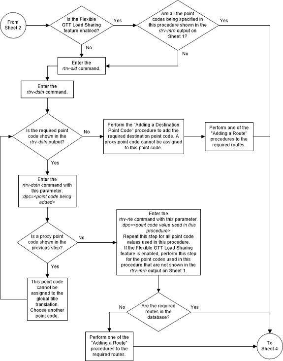
Figure 2-133 Provision MRN Entries - Sheet 4 of 5
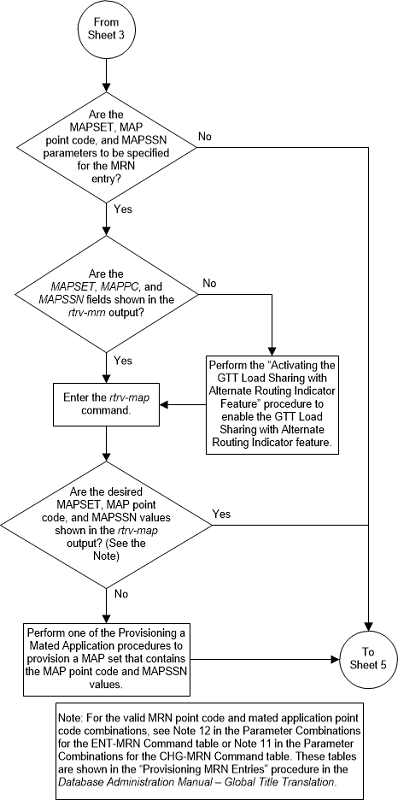
Figure 2-134 Provision MRN Entries - Sheet 5 of 5
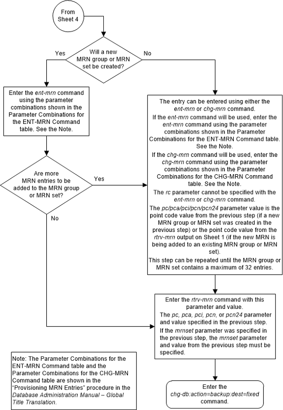
Removing MRN Entries
This procedure is used to remove an entry from an mated
relay node (MRN) group or an entire MRN group from the database using the
dlt-mrn command.
The
dlt-mrn command uses these parameters.
:pc/pca/pci/pcn/pcn24 –
The point code in the message after intermediate global title translation has
been performed.
:pc1/pca1/pci1/pcn1/pcn241 – The first alternate point
code value
:pc2/pca2/pci2/pcn2/pcn242 – The second alternate point
code value
:pc3/pca3/pci3/pcn3/pcn243 – The third alternate point
code value
:pc4/pca4/pci4/pcn4/pcn244 – The fourth alternate point
code value
Note:
Refer to Chapter 2, "Configuring Destination Tables," in Database Administration - SS7 User's Guide for a definition of the point code types that are used on the EAGLE and for a definition of the different formats that can be used for ITU national point codes.:all – Removes the entire
MRN group or MRN set containing the point code specified by the
pc/pca/pci/pcn/pcn24 parameter.
:mrnset – The MRN set ID
that the MRN is assigned to, shown in the
rtrv-mrn output. MRN set IDs are shown
only if the Flexible GTT Load Sharing feature is enabled. If the Flexible GTT
Load Sharing feature is enabled, the
mrnset parameter must be specified with
the
dlt-mrn command.
:mapset - The MAP set
ID assigned to the MRN set. This is the MAP set from which alternate routing
indicator searches are performed. The mapset parameter is shown in the
rtrv-mrn output only if the GTT Load
Sharing with Alternate Routing Indicator feature is enabled. An MRN set or a
point code in an MRN set cannot be removed if a MAP set is assigned to the MRN
set.
If an entire MRN set is being removed in this procedure
(with the
all=yes parameter), or if a point code
entry in an MRN set is being removed in this procedure, the reference to the
MRN set specified in this procedure must be removed from any GTT or GTA entries
before the point code can be removed from an MRN set, or before an entire MRN
set can be removed.
Perform one of these procedures to remove the reference
to the MRN set, depending on whether or not the EGTT feature is on. The status
of the EGTT feature is shown in the
rtrv-feat command output.
- If the EGTT feature is not on – Enter the
rtrv-gttcommand to verify the MRN set ID references. Perform the Changing a Global Title Translation procedure to remove the references to the MRN set. - If the EGTT feature is on – Enter the
rtrv-gtacommand to verify the MRN set ID references. Perform Changing Global Title Address Information to remove the references to the MRN set. The MRN set ID is not shown in thertrv-ppsoptoutput. - Any references to the MRN's point code and
non-default MRN set ID in the
rtrv-ppsoptsoutput are removed in 9 of this procedure. - Any references to the MRN's point code and
non-default MRN set ID in the
rtrv-gttactoutput are removed in 10 of this procedure.
Note:
If weight and in-service threshold values are assigned to a load shared or combined dominant/load shared MRN group or MRN set, and if by removing entries from this MRN group or MRN set, the MRN group or MRN set becomes a dominant MRN group or MRN set, all weight and threshold values are removed from the remaining entries in the MRN group or MRN set.The mated relay node group being removed, or the point code value being removed from a MRN group must be in the database.
When removing point codes from an MRN group, the MRN
group must contain the
pc parameter value and at least one
alternate point code value.
If the
mrnset=dflt and
all=yes parameters are specified with
the
dlt-mrn command, only the MRN group
containing the point code value specified in the
dlt-mrn command is removed from the
default MRN set.
Canceling the
RTRV-MRN Command
Because the
rtrv-mrn command used in this procedure
can output information for a long period of time, the
rtrv-mrn command can be canceled and
the output to the terminal stopped. There are three ways that the
rtrv-mrn command can be canceled.
- Press the
F9function key on the keyboard at the terminal where thertrv-mrncommand was entered. - Enter the
canc-cmdwithout thetrmparameter at the terminal where thertrv-mrncommand was entered. - Enter the
canc-cmd:trm=<xx>, where<xx>is the terminal where thertrv-mrncommand was entered, from another terminal other that the terminal where thertrv-mrncommand was entered. To enter thecanc-cmd:trm=<xx>command, the terminal must allow Security Administration commands to be entered from it and the user must be allowed to enter Security Administration commands. The terminal’s permissions can be verified with thertrv-secu-trmcommand. The user’s permissions can be verified with thertrv-userorrtrv-secu-usercommands.
For more information about the
canc-cmd command, refer to
Commands User's Guide.
Figure 2-135 Remove MRN Entries - Sheet 1 of 6
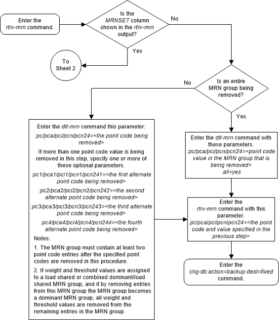
Figure 2-136 Remove MRN Entries - Sheet 2 of 6
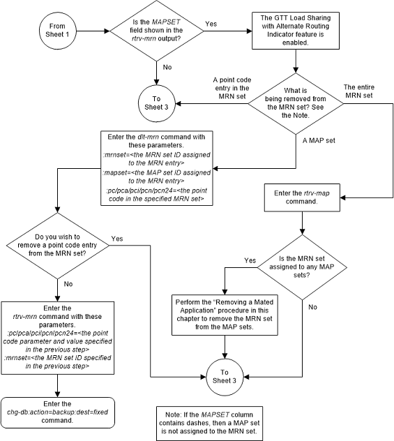
Figure 2-137 Remove MRN Entries - Sheet 3 of 6
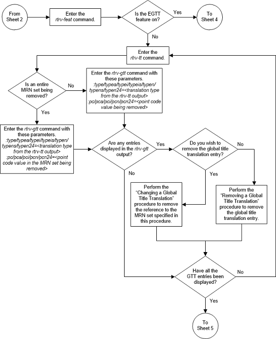
Figure 2-138 Remove MRN Entries - Sheet 4 of 6
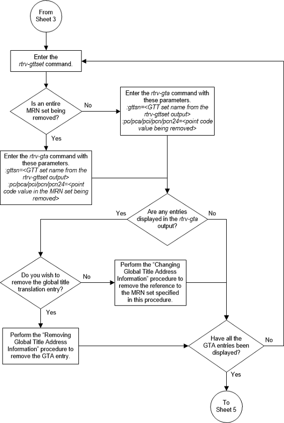
Figure 2-139 Remove MRN Entries - Sheet 5 of 6
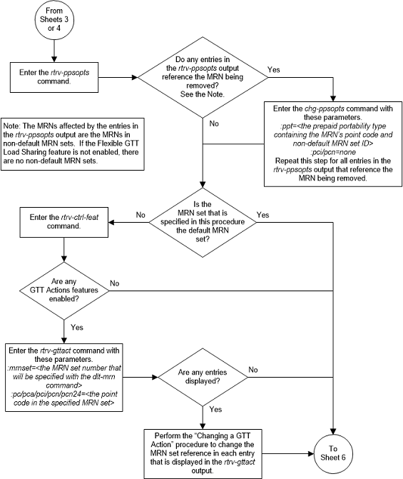
Figure 2-140 Remove MRN Entries - Sheet 6 of 6
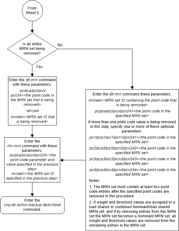
Changing the Relative Cost Values of MRN Entries
This procedure is used to change the relative cost
attributes of entries in an existing Mated Relay Node (MRN) group or MRN set
using
rc/rc1/rc2/rc3/
rc4 parameters of the
chg-mrn command.
The
chg-mrn command can also be used to add
point code entries to an existing MRN group or MRN set. This action is not
covered in this procedure. If you wish to add point code entries to an existing
MRN group or MRN set, perform
Provisioning MRN Entries
.
If you wish to assign the same weight and threshold value
to all the MRN entries in the MRN group or MRN set with the
eswt and
thr parameters, or to remove the weight
and threshold values from all the MRN entries in the MRN group or MRN set with
the
eswt=none parameter, perform
Changing MRN Entries with the ESWT Parameter.
The
eswt and
thr parameters cannot be used in this
procedure.
If you wish to change individual weight values for MRN
entries with the
wt/wt1/wt2/wt3/wt4 parameters, the
weight values for an RC group with the
grpwt parameter, the threshold values
for an MRN group or MRN set with the thr parameter, or the relative cost and
weight values for an MRN group or MRN set with the
force=yes parameter, perform
Changing the Weight and Threshold Values of MRN Entries.
The
wt/wt1/wt2/wt3/wt4,
grpwt,
thr, and
force=yes parameters cannot be used in
this procedure.
If you wish to change the MAP set, MAP point code, and
MAP SSN values assigned to an MRN set, using the
mapset,
mappc/mappca/mappci/mappcn/mappcn24,
and
mapssn parameters, perform
Changing the MAPSET, MAP Point Code, and MAP SSN Values of MRN Entries.
The
mapset,
mappc/mappca/mappci/mappcn/mappcn24,
and
mapssn parameters cannot be used in
this procedure.
An MRN group or MRN set contains alternate point codes, up to 32, that are used for load sharing between multiple nodes when the EAGLE is performing intermediate global title translation. This load sharing is performed after intermediate global title translation is performed on the message. The point code in the message is changed to the selected point code in the MRN table. If the translated point code is not found in the MRN table, the translated point code in the message is not changed, the message is routed using route for the translated point code.
These parameters are used with the
chg-mrn command in this procedure.
:pc/pca/pci/pcn/pcn24 –
The point code in the message after intermediate global title translation has
been performed.
:rc – The relative cost
value of point code in the message
:pc1/pca1/pci1/pcn1/pcn241 – The first alternate point
code value
:rc1 – The relative cost
value of the first alternate point code
:pc2/pca2/pci2/pcn2/pcn242 – The second alternate point
code value
:rc2 – The relative cost
value of the second alternate point code
:pc3/pca3/pci3/pcn3/pcn243 – The third alternate point
code value
:rc3 – The relative cost
value of the third alternate point code
:pc4/pca4/pci4/pcn4/pcn244 – The fourth alternate point
code value
:rc4 – The relative cost
value of the fourth alternate point code
Note:
Refer to Chapter 2, Configuring Destination Tables in Database Administration - SS7 User's Guide for a definition of the point code types that are used on the EAGLE and for a definition of the different formats that can be used for ITU national point codes.:mrnset – The MRN set ID
that the MRN is assigned to, shown in the
rtrv-mrn output. MRN set IDs are shown
only if the Flexible GTT Load Sharing feature is enabled. The
mrnset parameter value cannot be
changed in this procedure. For more information on the Flexible GTT Load
Sharing feature, refer to
Flexible GTT Load Sharing.
The relative cost parameter values (rc/rc1/rc2/rc3/rc4) determine how the global title translation load is
to be shared among the alternate point codes. There are three types of load
sharing that can be performed: dominant, load shared, or combined dominant/load
shared.
All the point codes in a dominant MRN group or MRN set have different relative cost values. The translated point code in the message is the preferred point code that the message is routed on. The relative cost value assigned to the preferred point code does not have to be the lowest value in the MRN group or MRN set. All traffic is routed to the preferred point code, if it is available. If the preferred point code becomes unavailable, the traffic is routed to highest priority alternate point code that is available. When the preferred point code becomes available again, the traffic is then routed back to the preferred point code. For example, the MRN table contains the following entries.
PC RC
005-005-005 10
006-001-001 20
006-001-002 30
006-001-003 40
006-001-004 50
006-001-005 60
006-001-006 70
006-001-007 80If the preferred point code is 006-001-001 and it becomes unavailable, the traffic will be routed to point code 006-001-002.
All the point codes in a load shared MRN group have the same relative cost value. Traffic is shared equally between the point codes in this MRN group.
A combined dominant/load shared MRN group or MRN set is a combination of the dominant and load sharing MRN groups or MRN sets. A combined dominant/load shared MRN group or MRN set must contain a minimum of two entries with the same relative cost value and a minimum of one entry with a different relative cost value. Traffic is routed to the point code or point codes with the lowest relative cost value. If more than one point code has the lowest relative cost value, the traffic is shared between these point codes. If the point code or point codes with the lowest relative cost value become unavailable, traffic is routed to the point code or point codes with the next higher relative cost value. If more than one point code has this relative cost value, the traffic is shared between these point codes. For example, the MRN table contains the following entries.
PC RC
005-005-005 10
006-001-001 10
006-001-002 10
006-001-003 20
006-001-004 20
006-001-005 20
006-001-006 20
006-001-007 20If the preferred point code is 006-001-001, the traffic is shared equally between point codes 005-005-005, 006-001-001, and 006-001-002. If point codes 005-005-005, 006-001-001, and 006-001-002 become unavailable, the traffic will be shared equally between point codes, 006-001-003, 006-001-004, 006-001-005, 006-001-006, and 006-001-007.
Canceling the
RTRV-MRN Command
Because the
rtrv-mrn command used in this procedure
can output information for a long period of time, the
rtrv-mrn command can be canceled and
the output to the terminal stopped. There are three ways that the
rtrv-mrn command can be canceled.
-
Press the
F9function key on the keyboard at the terminal where thertrv-mrncommand was entered. -
Enter the
canc-cmdwithout thetrmparameter at the terminal where thertrv-mrncommand was entered. -
Enter the
canc-cmd:trm=<xx>, where<xx>is the terminal where thertrv-mrncommand was entered, from another terminal other that the terminal where thertrv-mrncommand was entered. To enter thecanc-cmd:trm=<xx>command, the terminal must allow Security Administration commands to be entered from it and the user must be allowed to enter Security Administration commands. The terminal’s permissions can be verified with thertrv-secu-trmcommand. The user’s permissions can be verified with thertrv-userorrtrv-secu-usercommands.
For more information about the
canc-cmd command, refer to
Commands User's Guide.
Figure 2-141 Change the Relative Cost Values of MRN Entries
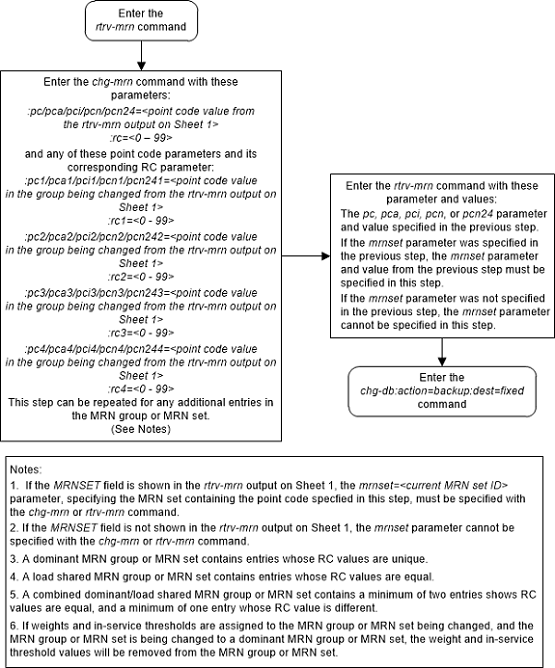
Changing MRN Entries with the ESWT Parameter
This procedure is used to change the weight values of all
the entries in an existing Mated Relay Node (MRN) group or MRN set using the
eswt parameter of the
chg-mrn command.
The
chg-mrn command can also be used to add
point code entries to an existing MRN group or MRN set. This action is not
covered in this procedure. If you wish to add point code entries to an existing
MRN group or MRN set, perform
Provisioning MRN Entries
.
If the MRN entries being changed do not have weight and threshold values assigned to them, perform Changing the Relative Cost Values of MRN Entries.
If you wish to change individual weight values for MRN
entries with the
wt/wt1/wt2/wt3/wt4 parameters, the
weight values for an RC group with the
grpwt parameter, the threshold values
for an MRN group or MRN set with the thr parameter, or the relative cost and
weight values for an MRN group or MRN set with the
force=yes parameter, perform
Changing the Weight and Threshold Values of MRN Entries.
The
wt/wt1/wt2/wt3/wt4,
grpwt,
thr, and
force=yes parameters cannot be used in
this procedure.
If you wish to change the MAP set, MAP point code, and
MAP SSN values assigned to an MRN set, using the
mapset,
mappc/mappca/mappci/mappcn/mappcn24,
and
mapssn parameters, perform
Changing the MAPSET, MAP Point Code, and MAP SSN Values of MRN Entries.
The
mapset,
mappc/mappca/mappci/mappcn/mappcn24,
and
mapssn parameters cannot be used in
this procedure.
An MRN group or MRN set contains alternate point codes, up to 32, that are used for load sharing between multiple nodes when the EAGLE is performing intermediate global title translation. This load sharing is performed after intermediate global title translation is performed on the message. The point code in the message is changed to the selected point code in the MRN table. If the translated point code is not found in the MRN table, the translated point code in the message is not changed, the message is routed using route for the translated point code.
These parameters are used with the
chg-mrn command in this procedure.
:pc/pca/pci/pcn/pcn24 –
The point code in the message after intermediate global title translation has
been performed.
:rc – The relative cost
value of point code in the message
:pc1/pca1/pci1/pcn1/pcn241 – The first alternate point
code value
:rc1 – The relative cost
value of the first alternate point code
:pc2/pca2/pci2/pcn2/pcn242 – The second alternate point
code value
:rc2 – The relative cost
value of the second alternate point code
:pc3/pca3/pci3/pcn3/pcn243 – The third alternate point
code value
:rc3 – The relative cost
value of the third alternate point code
:pc4/pca4/pci4/pcn4/pcn244 – The fourth alternate point
code value
:rc4 – The relative cost
value of the fourth alternate point code
Note:
Refer to Chapter 2, Configuring Destination Tables in Database Administration - SS7 User's Guide for a definition of the point code types that are used on the EAGLE and for a definition of the different formats that can be used for ITU national point codes.:mrnset – The MRN set ID
that the MRN is assigned to, shown in the
rtrv-mrn output. MRN set IDs are shown
only if the Flexible GTT Load Sharing feature is enabled. The
mrnset parameter value cannot be
changed in this procedure. For more information on the Flexible GTT Load
Sharing feature, refer to
Flexible GTT Load Sharing.
:eswt – The entity set
weight value. When this parameter is specified, the same weight value is
assigned to all entries in the MRN group or MRN set that contain the point code
value specified in the
chg-mrn command. A MRN group or MRN set
can also be referred to as an entity set. The value of this parameter is from 1
- 99.
:thr – The in-service
threshold assigned to the MRN group or MRN set. The in-service threshold is the
minimum percentage (from 1 - 100) of weight that must be available for an RC
group (a group of entries in the MRN group or MRN set that have the same RC
value assigned) to be considered available to carry traffic. If the percentage
of the available weight is less than the in-service threshold, then the entire
RC group is considered unavailable for traffic. If the percentage of the
available weight is equal to or greater than the in-service threshold, then the
RC group is considered available, and traffic can be sent to any available
entity in the RC group. When the
thr parameter is specified with the
eswt parameter in this procedure, the
in-service threshold value is assigned to all the entries of the MRN group or
MRN set.
The relative cost parameter values (rc/rc1/rc2/rc3/rc4) determine how the global title translation load is
to be shared among the alternate point codes. There are three types of load
sharing that can be performed: dominant, load shared, or combined dominant/load
shared.
All the point codes in a dominant MRN group or MRN set have different relative cost values. The translated point code in the message is the preferred point code that the message is routed on. The relative cost value assigned to the preferred point code does not have to be the lowest value in the MRN group or MRN set. All traffic is routed to the preferred point code, if it is available. If the preferred point code becomes unavailable, the traffic is routed to highest priority alternate point code that is available. When the preferred point code becomes available again, the traffic is then routed back to the preferred point code. For example, the MRN table contains the following entries.
PC RC
005-005-005 10
006-001-001 20
006-001-002 30
006-001-003 40
006-001-004 50
006-001-005 60
006-001-006 70
006-001-007 80If the preferred point code is 006-001-001 and it becomes unavailable, the traffic will be routed to point code 006-001-002.
All the point codes in a load shared MRN group have the same relative cost value. Traffic is shared equally between the point codes in this MRN group.
A combined dominant/load shared MRN group or MRN set is a combination of the dominant and load sharing MRN groups or MRN sets. A combined dominant/load shared MRN group or MRN set must contain a minimum of two entries with the same relative cost value and a minimum of one entry with a different relative cost value. Traffic is routed to the point code or point codes with the lowest relative cost value. If more than one point code has the lowest relative cost value, the traffic is shared between these point codes. If the point code or point codes with the lowest relative cost value become unavailable, traffic is routed to the the point code or point codes with the next higher relative cost value. If more than one point code has this relative cost value, the traffic is shared between these point codes. For example, the MRN table contains the following entries.
PC RC
005-005-005 10
006-001-001 10
006-001-002 10
006-001-003 20
006-001-004 20
006-001-005 20
006-001-006 20
006-001-007 20If the preferred point code is 006-001-001, the traffic is shared equally between point codes 005-005-005, 006-001-001, and 006-001-002. If point codes 005-005-005, 006-001-001, and 006-001-002 become unavailable, the traffic will be shared equally between point codes, 006-001-003, 006-001-004, 006-001-005, 006-001-006, and 006-001-007.
The
eswt and
thr parameters can be used only:
- If the MRN group or MRN set is either a load shared or combined dominant/load shared MRN group or MRN set.
- If the Weighted GTT Load Sharing feature is enabled and turned on.
The status of the Weighted GTT Load Sharing feature can
be verified by entering the
rtrv-ctrl-feat command. If the Weighted
GTT Load Sharing feature is not enabled or not turned on, perform
Activating the Weighted GTT Load Sharing Feature
to enable and turn on the Weighted GTT Load Sharing feature.
The
eswt parameter assigns same weight
value to all the entries in the MRN group or MRN set that contains the point
code value specified in the
chg-mrn command.
The
eswt and
thr parameters can be specified with
the
chg-mrn command only with the
pc/pca/pci/pcn/pcn24 parameter and
without the alternate point code, relative cost (rc,
rc1,
rc2,
rc3,
rc4), group weight (grpwt), and individual weight (wt,
wt1,
wt2,
wt3,
wt4) parameters.
The weight values assigned to the entires in the MRN
group or MRN set are shown in the
WT column in the
rtrv-mrn output.
The in-service threshold values assigned to the entires
in the MRN group or MRN set are shown in the
THR column in the
rtrv-mrn output.
The
%WT column in the
rtrv-mrn output shows the percentage of
the traffic the particular entry in the entity set will handle.
The
WT,
%WT, and
THR columns are shown in the
rtrv-mrn output only if the Weighted
GTT Load Sharing feature is enabled and turned on.
For more information on the Weighted GTT Load Sharing feature, refer to Weighted GTT Load Sharing.
Canceling the
RTRV-MRN Command
Because the
rtrv-mrn command used in this procedure
can output information for a long period of time, the
rtrv-mrn command can be canceled and
the output to the terminal stopped. There are three ways that the
rtrv-mrn command can be canceled.
- Press the
F9function key on the keyboard at the terminal where thertrv-mrncommand was entered. - Enter the
canc-cmdwithout thetrmparameter at the terminal where thertrv-mrncommand was entered. - Enter the
canc-cmd:trm=<xx>, where<xx>is the terminal where thertrv-mrncommand was entered, from another terminal other that the terminal where thertrv-mrncommand was entered. To enter thecanc-cmd:trm=<xx>command, the terminal must allow Security Administration commands to be entered from it and the user must be allowed to enter Security Administration commands. The terminal’s permissions can be verified with thertrv-secu-trmcommand. The user’s permissions can be verified with thertrv-userorrtrv-secu-usercommands.
For more information about the
canc-cmd command, refer to
Commands User's Guide.
Figure 2-142 Change MRN Entries with the ESWT Parameter - Sheet 1 of 4
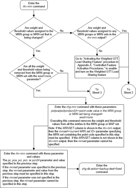
Figure 2-143 Change MRN Entries with the ESWT Parameter - Sheet 2 of 4
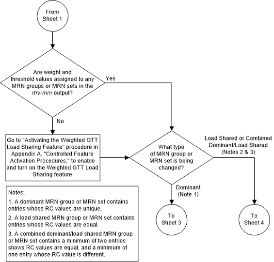
Figure 2-144 Change MRN Entries with the ESWT Parameter - Sheet 3 of 4
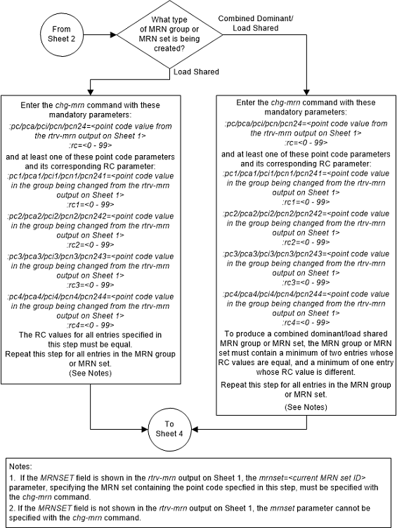
Figure 2-145 Change MRN Entries with the ESWT Parameter - Sheet 4 of 4
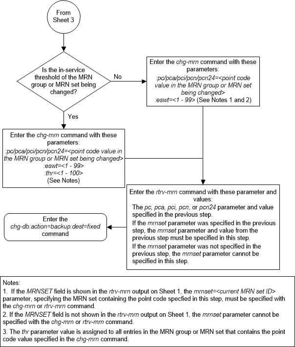
Changing the Weight and Threshold Values of MRN Entries
This procedure is used to change the weight and threshold
values of entries in an existing Mated Relay Node (MRN) group or MRN set to new
weight and threshold values. The weight and threshold values are changed using
the
chg-mrn command. This procedure can be
performed only on MRN entries that have weight and thresholds assigned.
The following changes can be made in this procedure:
-
The individual weight values of the entries in the MRN group or MRN set with the
wt/wt1/wt2/wt3/wt4parameters. -
The individual weight and relative cost values of the entries in the MRN group or MRN set with the
wt/wt1/wt2/wt3/wt4,rc/rc1/rc2/rc3/rc4, andforce=yesparameters. -
The threshold values of the entities in the MRN group or MRN set that have the same relative cost value with the
thrparameter. The new threshold value is assigned to the entities in the MRN group or MRN set that have the same relative cost value. -
The weight values of the entities in the MRN group or MRN set that have the same relative cost value with the
grpwtparameter. The new weight value is assigned to the entities in the MRN group or MRN set that have the same relative cost value. -
The threshold and weight values of the entities in the MRN group or MRN set that have the same relative cost value with the
thrandgrpwtparameters. The new threshold and weight value is assigned to the entities in the MRN group or MRN set that have the same relative cost value.
The
chg-mrn command can also be used to add
point code entries to an existing MRN group or MRN set. This action is not
covered in this procedure. If you wish to add point code entries to an existing
MRN group or MRN set, perform
Provisioning MRN Entries
.
If the MRN entries being changed do not have weight and threshold values assigned to them, perform Changing the Relative Cost Values of MRN Entries.
If you wish to assign the same weight and threshold value
to all the MRN entries in the MRN group or MRN set with the
eswt and
thr parameters, or to remove the weight
and threshold values from all the MRN entries in the MRN group or MRN set with
the
eswt=none parameter, perform
Changing MRN Entries with the ESWT Parameter.
The
eswt parameter cannot be used in this
procedure.
If you wish to change the MAP set, MAP point code, and
MAP SSN values assigned to an MRN set, using the
mapset,
mappc/mappca/mappci/mappcn/mappcn24,
and
mapssn parameters, perform
Changing the MAPSET, MAP Point Code, and MAP SSN Values of MRN Entries.
The
mapset,
mappc/mappca/mappci/mappcn/mappcn24,
and
mapssn parameters cannot be used in
this procedure.
An MRN group or MRN set contains alternate point codes, up to 32, that are used for load sharing between multiple nodes when the EAGLE is performing intermediate global title translation. This load sharing is performed after intermediate global title translation is performed on the message. The point code in the message is changed to the selected point code in the MRN table. If the translated point code is not found in the MRN table, the translated point code in the message is not changed, the message is routed using route for the translated point code.
The
chg-mrn command uses these parameters.
:pc/pca/pci/pcn/pcn24 –
The point code in the message after intermediate global title translation has
been performed.
:rc – The relative cost
value of point code in the message
:pc1/pca1/pci1/pcn1/pcn241 – The first alternate point
code value
:rc1 – The relative cost
value of the first alternate point code
:pc2/pca2/pci2/pcn2/pcn242 – The second alternate point
code value
:rc2 – The relative cost
value of the second alternate point code
:pc3/pca3/pci3/pcn3/pcn243 – The third alternate point
code value
:rc3 – The relative cost
value of the third alternate point code
:pc4/pca4/pci4/pcn4/pcn244 – The fourth alternate point
code value
:rc4 – The relative cost
value of the fourth alternate point code
Note:
Refer to Chapter 2, Configuring Destination Tables in Database Administration - SS7 User's Guide for a definition of the point code types that are used on the EAGLE and for a definition of the different formats that can be used for ITU national point codes.:mrnset – The MRN set ID
that the MRN is assigned to, shown in the
rtrv-mrn output. MRN set IDs are shown
only if the Flexible GTT Load Sharing feature is enabled. The
mrnset parameter value cannot be
changed in this procedure. For more information on the Flexible GTT Load
Sharing feature, refer to
Flexible GTT Load Sharing.
:grpwt – The group weight
value. When this parameter is specified, the same weight value is assigned to
all entries that have the same RC (relative cost) value in the MRN group or MRN
set that contain the point code specified in the
chg-mrn command. The value of this
parameter is from 1 - 99.
:wt – The weight value
assigned to the
pc/pca/pci/pcn/pcn24 parameter
value. The value of this parameter is from 1 - 99.
:wt1 – The weight value
assigned to the
pc1/pca1/pci1/pcn1/pcn241 parameter
value. The value of this parameter is from 1 - 99.
:wt2 – The weight value
assigned to the
pc2/pca2/pci2/pcn2/pcn242 parameter
value. The value of this parameter is from 1 - 99.
:wt3 – The weight value
assigned to the
pc3/pca3/pci3/pcn3/pcn243 parameter
value. The value of this parameter is from 1 - 99.
:wt4 – The weight value
assigned to the
pc4/pca4/pci4/pcn4/pcn244 parameter
value.
:thr – The in-service
threshold assigned to the MRN group or MRN set. The in-service threshold is the
minimum percentage (from 1 - 100) of weight that must be available for an RC
group (a group of entries in the MRN group or MRN set that have the same RC
value assigned) to be considered available to carry traffic. If the percentage
of the available weight is less than the in-service threshold, then the entire
RC group is considered unavailable for traffic. If the percentage of the
available weight is equal to or greater than the in-service threshold, then the
RC group is considered available, and traffic can be sent to any available
entity in the RC group. The value of the
thr parameter is assigned to all
entries that have the same RC (relative cost) value in the MRN group or MRN set
that contain the point code specified in the
chg-mrn command.
:force=yes – This
parameter must be specified if the
rc/rc1/rc2/rc3/rc4 parameter is specified with the
wt/wt1/wt2/wt3/wt4 parameter.
The relative cost parameter values (rc/rc1/rc2/rc3/rc4) determine how the global title translation load is
to be shared among the alternate point codes. There are three types of load
sharing that can be performed: dominant, load shared, or combined dominant/load
shared.
All the point codes in a dominant MRN group or MRN set have different relative cost values. The translated point code in the message is the preferred point code that the message is routed on. The relative cost value assigned to the preferred point code does not have to be the lowest value in the MRN group or MRN set. All traffic is routed to the preferred point code, if it is available. If the preferred point code becomes unavailable, the traffic is routed to highest priority alternate point code that is available. When the preferred point code becomes available again, the traffic is then routed back to the preferred point code. For example, the MRN table contains the following entries.
PC RC
005-005-005 10
006-001-001 20
006-001-002 30
006-001-003 40
006-001-004 50
006-001-005 60
006-001-006 70
006-001-007 80If the preferred point code is 006-001-001 and it becomes unavailable, the traffic will be routed to point code 006-001-002.
All the point codes in a load shared MRN group have the same relative cost value. Traffic is shared equally between the point codes in this MRN group.
A combined dominant/load shared MRN group or MRN set is a combination of the dominant and load sharing MRN groups or MRN sets. A combined dominant/load shared MRN group or MRN set must contain a minimum of two entries with the same relative cost value and a minimum of one entry with a different relative cost value. Traffic is routed to the point code or point codes with the lowest relative cost value. If more than one point code has the lowest relative cost value, the traffic is shared between these point codes. If the point code or point codes with the lowest relative cost value become unavailable, traffic is routed to the the point code or point codes with the next higher relative cost value. If more than one point code has this relative cost value, the traffic is shared between these point codes. For example, the MRN table contains the following entries.
PC RC
005-005-005 10
006-001-001 10
006-001-002 10
006-001-003 20
006-001-004 20
006-001-005 20
006-001-006 20
006-001-007 20If the preferred point code is 006-001-001, the traffic is shared equally between point codes 005-005-005, 006-001-001, and 006-001-002. If point codes 005-005-005, 006-001-001, and 006-001-002 become unavailable, the traffic will be shared equally between point codes, 006-001-003, 006-001-004, 006-001-005, 006-001-006, and 006-001-007.
Specifying the
grpwt or
thr parameter with the
chg-mrn command can be done when
specifying only the
pc/pca/pci/pcn/pcn24 parameter and
without the alternate point code, relative cost (rc,
rc1,
rc2,
rc3,
rc4), and individual weight (wt,
wt1,
wt2,
wt3,
wt4) parameters.
The weight values assigned to the entires in the MRN
group or MRN set are shown in the
WT column in the
rtrv-mrn output.
The in-service threshold values assigned to the entires
in the MRN group or MRN set are shown in the
THR column in the
rtrv-mrn output.
The
%WT column in the
rtrv-mrn output shows the percentage of
the traffic the particular entry in the entity set will handle.
The
WT,
%WT, and
THR columns are shown in the
rtrv-mrn output only if the Weighted
GTT Load Sharing feature is enabled and turned on.
For more information on the Weighted GTT Load Sharing feature, refer to Weighted GTT Load Sharing.
Canceling the
RTRV-MRN Command
Because the
rtrv-mrn command used in this procedure
can output information for a long period of time, the
rtrv-mrn command can be canceled and
the output to the terminal stopped. There are three ways that the
rtrv-mrn command can be canceled.
- Press the
F9function key on the keyboard at the terminal where thertrv-mrncommand was entered. - Enter the
canc-cmdwithout thetrmparameter at the terminal where thertrv-mrncommand was entered. - Enter the
canc-cmd:trm=<xx>, where<xx>is the terminal where thertrv-mrncommand was entered, from another terminal other that the terminal where thertrv-mrncommand was entered. To enter thecanc-cmd:trm=<xx>command, the terminal must allow Security Administration commands to be entered from it and the user must be allowed to enter Security Administration commands. The terminal’s permissions can be verified with thertrv-secu-trmcommand. The user’s permissions can be verified with thertrv-userorrtrv-secu-usercommands.
For more information about the
canc-cmd command, refer to
Commands User's Guide.
Figure 2-146 Change the Weight and Threshold Values of MRN Entries - Sheet 1 of 4
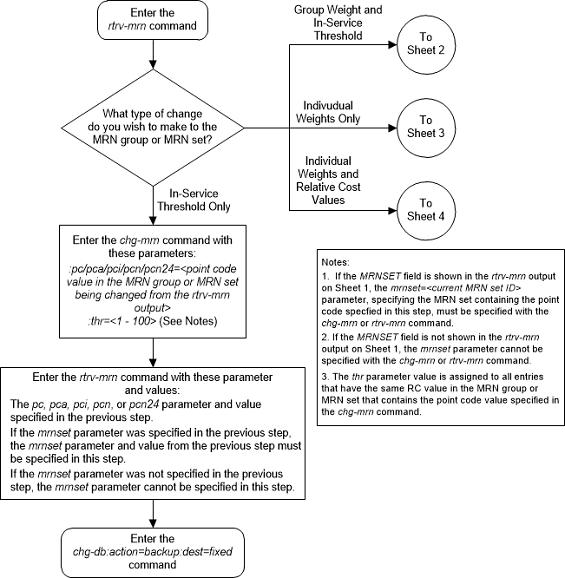
Figure 2-147 Change the Weight and Threshold Values of MRN Entries - Sheet 2 of 4
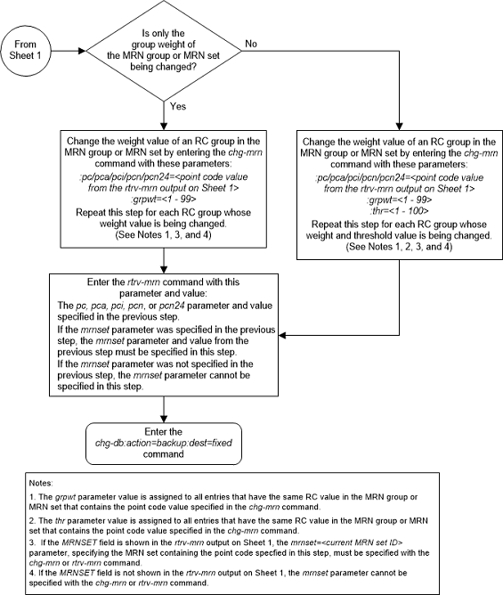
Figure 2-148 Change the Weight and Threshold Values of MRN Entries - Sheet 3 of 4
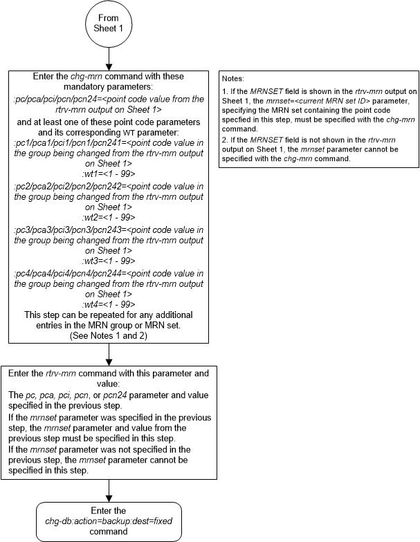
Figure 2-149 Change the Weight and Threshold Values of MRN Entries - Sheet 4 of 4
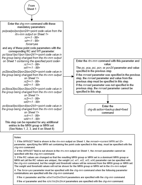
Changing the MAPSET, MAP Point Code, and MAP SSN Values of MRN Entries
This procedure is used to change the MAPSET, MAP point
code, and MAP SSN values in an existing Mated Relay Node (MRN) set using the
mapset,
mappc/mappca/mappci/
mappcn/mappcn24, and
mapssn parameters of the
chg-mrn command.
The
chg-mrn command can also be used to
add point code entries to an existing MRN set. This action is not covered in
this procedure. If you wish to add point code entries to an existing MRN set,
perform
Provisioning MRN Entries.
If you wish to assign the same weight and threshold
value to all the entries in the MRN set with the
eswt and
thr parameters, or to remove the
weight and threshold values from all the entries in the MRN set with the
eswt=none parameter, perform
Changing MRN Entries with the ESWT Parameter.
The
eswt and
thr parameters cannot be used in this
procedure.
If you wish to change individual weight values for
entries with the
wt/wt1/wt2/wt3/wt4 parameters,
the weight values for an RC group with the
grpwt parameter, the threshold values
for an MRN set with the thr parameter, or the relative cost and weight values
for an MRN set with the
force=yes parameter, perform
Changing the Weight and Threshold Values of MRN Entries.
The
wt/wt1/wt2/wt3/wt4,
grpwt,
thr, and
force=yes parameters cannot be used in
this procedure.
These parameters are used with the
chg-mrn command in this procedure.
:pc/pca/pci/pcn/pcn24 –
The point code in the message after intermediate global title translation has
been performed.
:mrnset – The MRN set
ID that is being changed.
:mapset – The MAP set
ID that is being assigned to the MRN. This is the MAP set from which alternate
routing indicator searches are performed.
:mappc/mappca/mappci/mappcn/mappcn24 – The point code
assigned to the
mapset that is being assigned to the
MRN set.
:mapssn – The subsystem
number assigned to the point code in the MAP set that is being assigned to the
MRN.
Note:
Refer to Chapter 2, Configuring Destination Tables in Database Administration - SS7 User's Guide for a definition of the point code types that are used on the EAGLE and for a definition of the different formats that can be used for ITU national point codes.The current values of the
mapset,
:mappc/mappca/mappci/mappcn/mappcn24,
and
mapssn parameters are shown in the
rtrv-mrn output only if the Flexible
GTT Load Sharing and the GTT Load Sharing with Alternate Routing Indicator
features are enabled.
The new values for the
mapset,
mappc/mappca/mappci/mappcn/mappcn24,
and
mapssn parameters must be shown in the
rtrv-map output.
The network type of the
pc/pca/pci/pcn/pcn24 and
mappc/mappca/mappci/mappcn/mappcn24
parameter values must be compatible, as shown in
Table 2-57.
Table 2-57 MRN and MAP Point Code Parameter Combinations
| MRN Point Code Parameter | MAP Point Code Parameter |
|---|---|
| pc/pca | mappc/mappca |
| pci or pcn (See Notes 1 and 2) | mappci or mappcn (See Notes 1 and 2) |
| pcn24 | mappcn24 |
|
Notes: 1. If the network type of the MRN point code parameter is
ITU-I ( 2. If the network type of the MRN point code parameter is
ITU-N ( |
|
Canceling the
RTRV-MRN Command
Because the
rtrv-mrn command used in this
procedure can output information for a long period of time, the
rtrv-mrn command can be canceled and
the output to the terminal stopped. There are three ways that the
rtrv-mrn command can be canceled.
- Press the
F9function key on the keyboard at the terminal where thertrv-mrncommand was entered. - Enter the
canc-cmdwithout thetrmparameter at the terminal where thertrv-mrncommand was entered. - Enter the
canc-cmd:trm=<xx>, where<xx>is the terminal where thertrv-mrncommand was entered, from another terminal other that the terminal where thertrv-mrncommand was entered. To enter thecanc-cmd:trm=<xx>command, the terminal must allow Security Administration commands to be entered from it and the user must be allowed to enter Security Administration commands. The terminal’s permissions can be verified with thertrv-secu-trmcommand. The user’s permissions can be verified with thertrv-userorrtrv-secu-usercommands.
For more information about the
canc-cmd command, refer to
Commands User's Guide.
Figure 2-150 Change the MAPSET, MAP Point Code, and MAP SSN Values of MRN Entries - Sheet 1 of 2
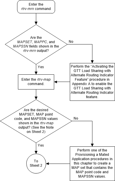
Figure 2-151 Change the MAPSET, MAP Point Code, and MAP SSN Values of MRN Entries - Sheet 2 of 2
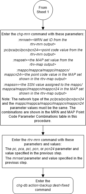
Adding a GT Conversion Table Entry
This procedure is used to provision an entry in the GT
Conversion table for the ANSI/ITU SCCP Conversion feature using the
ent-gtcnv command.
The
ent-gtcnv command uses these
parameters.
:dir – The direction that
the conversion takes place
atoa – The conversion
takes place in the ANSI to ITU direction
itoa – The conversion
takes place in the ITU to ANSI direction
both – The conversion
takes place in the ANSI to ITU and ITU to ANSI directions
:gtixlat – The global
title indicator types being converted.
22 – ANSI GTI type 2 to
ITU GTI type 2
24 – ANSI GTI type 2 to
ITU GTI type 4
:tta – The ANSI
translation type
:tti – The ITU
translation type
:np – The numbering plan
:nai – The nature of
address indicator
:npdd – The number of
digits to be deleted or substituted from the beginning of the Global Title
Address digits (the prefix digits)
:npds – The digits that
are being substituted for the prefix digits
:nsdd – The number of
digits to be deleted or substituted from the end of the Global Title Address
digits (the suffix digits)
:nsds – The digits that
are being substituted for the suffix digits
To perform this procedure, the ANSI/ITU SCCP Conversion
feature must be enabled. Enter the
rtrv-ctrl-feat command to verify
whether or not the ANSI/ITU SCCP Conversion is enabled. If the ANSI/ITU SCCP
Conversion feature is not enabled, perform the
Activating the ANSI/ITU SCCP Conversion Feature
procedure to enabled the ANSI/ITU SCCP Conversion feature.
Note:
The ANSI/ITU SCCP Conversion feature can only be permanently enabled.The
gtixlat parameter determines how the
tta,
tti,
np, and
nai parameters are used with the
ent-gtcnv command.
If the
gtixlat parameter value is
22, only the
tta,
tti,
npdd,
npds,
nsdd, and
nsds parameters can be specified. The
tta and
tti parameters must be specified along
with the
dir and
gtixlat=22 parameters.
If the
gtixlat parameter value is
24, the
tta,
tti,
np,
nai,
npdd,
npds,
nsdd, and
nsds parameters can be specified. The
tta,
tti,
np, and
nai parameters must be specified along
with the
dir and
gtixlat=24 parameters.
Asterisks (*) can be specified for the
tta,
tti,
np, and
nai parameters indicating all possible
values for that parameter. The
dir and
gtixlat parameters determine when the
asterisk can be used.
If the
dir parameter is
atoi, the asterisk can be specified
only for the
tta parameter.
If the
dir parameter is
itoa and the
gtixlat parameter is
24, the asterisk can be specified for
the
tti,
np, and
nai parameters. If the asterisk is
specified for either the
tti,
np, or
nai parameters, the asterisk must be
specified for the
tti,
np, and
nai parameters.
The asterisk cannot be specified for any parameter when
the
dir parameter value is
both.
The optional prefix (npdd,
npds) and suffix parameters (nsdd,
nsds) can be specified, but both sets
of parameters, or a mixture of the prefix and suffix parameters cannot be
specified. For example, if the either the
npdd or
npds parameters are specified, the
nsdd and
nsds cannot be specified. If either the
nsdd or
nsds parameters are specified, the
npdd and
npds parameters cannot be specified.
Figure 2-152 Add a GT Conversion Table Entry - Sheet 1 of 4
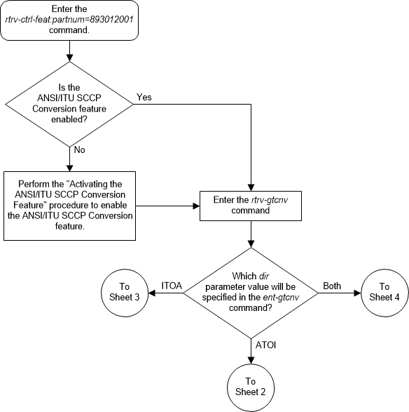
Figure 2-153 Add a GT Conversion Table Entry - Sheet 2 of 4
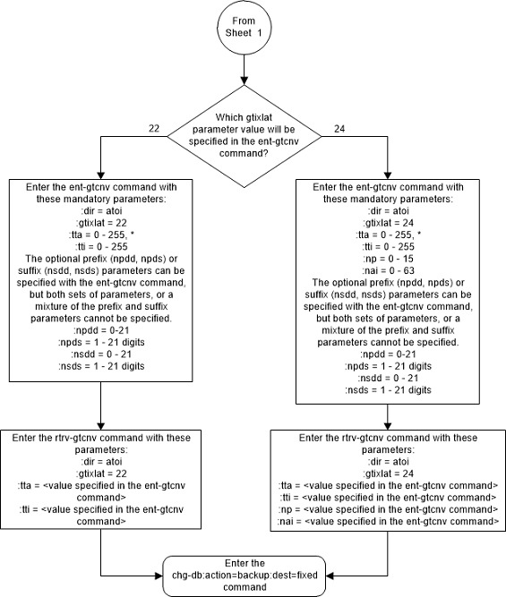
Figure 2-154 Add a GT Conversion Table Entry - Sheet 3 of 4
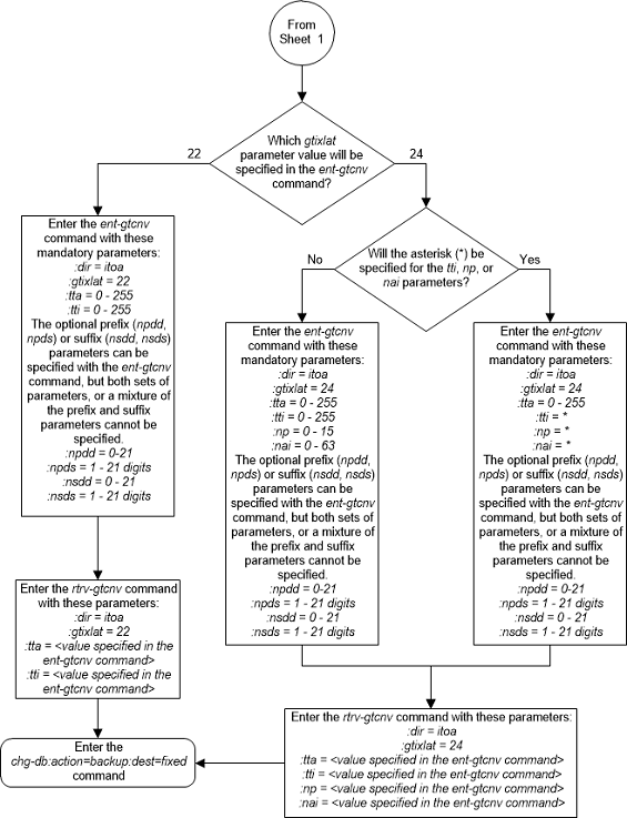
Figure 2-155 Add a GT Conversion Table Entry - Sheet 4 of 4
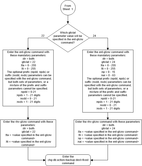
Removing a GT Conversion Table Entry
This procedure is used to remove an entry from the GT
Conversion table using the
dlt-gtcnv command.
The
dlt-gtcnv command uses these
parameters.
:dir – The direction that
the conversion takes place
atoa – The conversion
takes place in the ANSI to ITU direction
itoa – The conversion
takes place in the ITU to ANSI direction
both – The conversion
takes place in the ANSI to ITU and ITU to ANSI directions
:tta – The ANSI
translation type
:tti – The ITU
translation type
:np – The numbering plan
:nai – The nature of
address indicator
To perform this procedure, the ANSI/ITU SCCP Conversion
feature must be enabled. Enter the
rtrv-ctrl-feat command to verify
whether or not the ANSI/ITU SCCP Conversion is enabled.
Note:
The ANSI/ITU SCCP Conversion feature can only be permanently enabled.The
gtixlat and
dir parameter values in the GT
Conversion Table entry determines how the
tta,
tti,
np, and
nai parameters are used with the
dlt-gtcnv command.
- If the
dirparameter isatoi, only thedir=atoiandttaparameters can be and must be specified with thedlt-gtcnvcommand. - If the
dirparameter isitoaand thegtixlatparameter is22, only thedir=itoaandttiparameter can be and must be specified with thedlt-gtcnvcommand. - If the
dirparameter isitoaand thegtixlatparameter is24, only thedir=itoa,tti,np, andnaiparameters can be and must be specified for thedlt-gtcnvcommand. - If the
dirparameter isbothand thegtixlatparameter is22, only thedir=both,tta, andttiparameters can be and must be specified with thedlt-gtcnvcommand. - If the
dirparameter isbothand thegtixlatparameter is24, thedir=both,tta,tti,np, andnaiparameters can be and must be specified for thedlt-gtcnvcommand.
The values for the parameters of the GT Conversion Table
entry being removed must be entered as shown in the
rtrv-gtcnv output.
The GT Conversion Table entry specified in the
dlt-gtcnv command must be shown in the
rtrv-gtcnv output.
Figure 2-156 Remove a GT Conversion Table Entry - Sheet 1 of 4
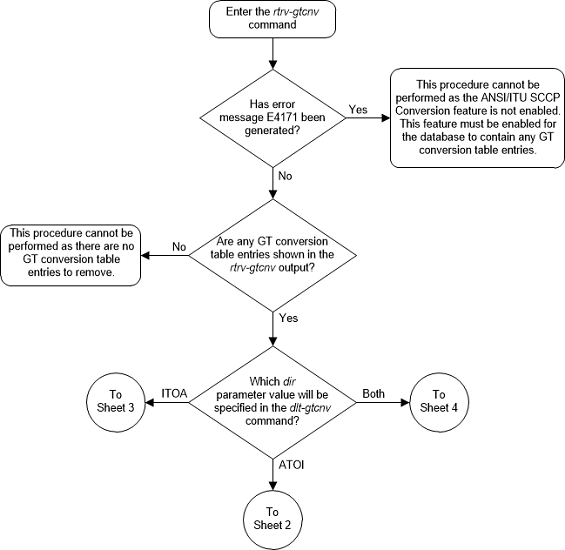
Figure 2-157 Remove a GT Conversion Table Entry - Sheet 2 of 4
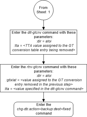
Figure 2-158 Remove a GT Conversion Table Entry - Sheet 3 of 4
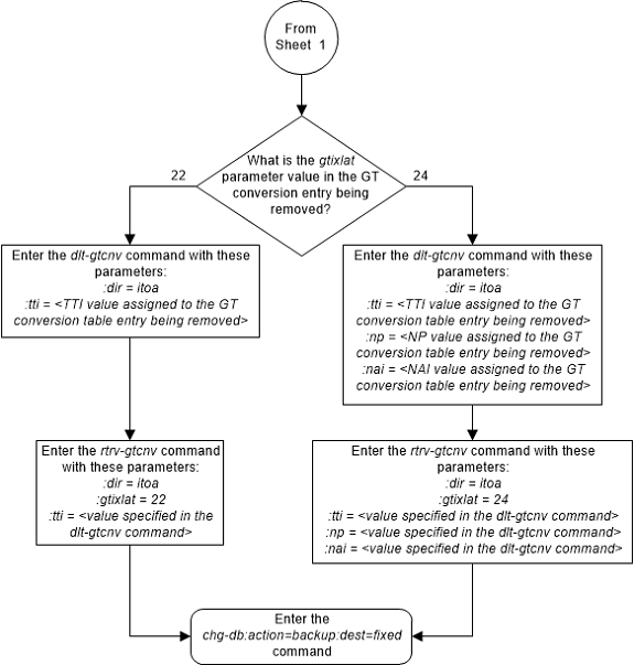
Figure 2-159 Remove a GT Conversion Table Entry - Sheet 4 of 4
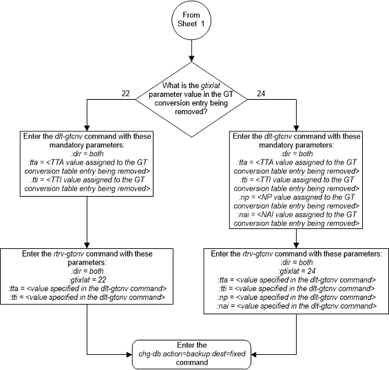
Changing a GT Conversion Table Entry
This procedure is used to provision an entry in the GT
Conversion table for the ANSI/ITU SCCP Conversion feature using the
chg-gtcnv command.
The
chg-gtcnv command uses these
parameters.
:dir – The direction that
the conversion takes place
atoa – The conversion
takes place in the ANSI to ITU direction
itoa – The conversion
takes place in the ITU to ANSI direction
both – The conversion
takes place in the ANSI to ITU and ITU to ANSI directions
:tta – The ANSI
translation type
:tti – The ITU
translation type
:np – The numbering plan
:nai – The nature of
address indicator
:npdd – The number of
digits to be deleted or substituted from the beginning of the Global Title
Address digits (the prefix digits)
:npds – The digits that
are being substituted for the prefix digits
:nsdd – The number of
digits to be deleted or substituted from the end of the Global Title Address
digits (the suffix digits)
:nsds – The digits that
are being substituted for the suffix digits
:rdmod – This parameter
specifies whether or not the existing
npdd,
npds,
nsdd,
nsds parameter values are removed from
the GT Conversion Table entry. If the value of this parameter is
yes, the existing
npdd,
npds,
nsdd,
nsds parameter values are removed from
the GT Conversion Table entry. If the value of this parameter is
no, the default value, the existing
npdd,
npds,
nsdd,
nsds parameter values are not removed
from the GT Conversion Table entry.
To perform this procedure, the ANSI/ITU SCCP Conversion
feature must be enabled. Enter the
rtrv-ctrl-feat command to verify
whether or not the ANSI/ITU SCCP Conversion is enabled.
Note:
The ANSI/ITU SCCP Conversion feature can only be permanently enabled.The
gtixlat and
dir parameter values in the GT
Conversion Table entry determines how the
tta,
tti,
np,
nai,
npdd,
npds,
nsdd,
nsds, and
rdmod parameters are used with the
chg-gtcnv command.
- If the
dirparameter isatoi, thedir=atoiandttaparameters must be specified with thechg-gtcnvcommand. If thegtixlatparameter is22, the optional parameterstti,npdd,npds,nsdd,nsds, andrdmodcan be specified with thechg-gtcnvcommand. If thegtixlatparameter is24, the optional parameterstti,np,nai,npdd,npds,nsdd,nsds, andrdmodcan be specified with thechg-gtcnvcommand. - If the
dirparameter isitoaand thegtixlatparameter is22, thedir=itoaandttiparameters must be specified with thechg-gtcnvcommand. The optional parameterstta,npdd,npds,nsdd,nsds, andrdmodcan be specified with thechg-gtcnvcommand. - If the
dirparameter isitoaand thegtixlatparameter is24, thedir=itoaandtti,np, andnaiparameters must be specified with thechg-gtcnvcommand. The optional parameterstta,npdd,npds,nsdd,nsds, andrdmodcan be specified with thechg-gtcnvcommand. - If the
dirparameter isbothand thegtixlatparameter is22, thedir=both,tta, andttiparameters must be specified with thechg-gtcnvcommand. The optional parametersnpdd,npds,nsdd,nsds, andrdmodcan be specified with thechg-gtcnvcommand. - If the
dirparameter isbothand thegtixlatparameter is24, thedir=both,tta,tti,np, andnaiparameters must be specified with thechg-gtcnvcommand. The optional parametersnpdd,npds,nsdd,nsds, andrdmodcan be specified with thechg-gtcnvcommand.
If the
rdmod=yes parameter is specified with
the
chg-gtcnv command, the
npdd,
npds,
nsdd, and
nsds parameters cannot be specified.
If the
npdd,
npds,
nsdd, or
nsds parameters are specified with the
chg-gtcnv command, the
rdmod=yes parameter cannot be
specified.
The optional prefix (npdd,
npds) and suffix parameters (nsdd,
nsds) can be specified, but both sets
of parameters, or a mixture of the prefix and suffix parameters cannot be
specified. For example, if the either the
npdd or
npds parameters are specified, the
nsdd and
nsds cannot be specified. If either the
nsdd or
nsds parameters are specified, the
npdd and
npds parameters cannot be specified.
The prefix or suffix parameter values assigned to a GT
Conversion Table entry can be changed from one type to another type, (prefix
parameter values to suffix parameter values or suffix parameter values to
prefix parameter values). To change the prefix values to suffix values or
suffix values to prefix values, the existing prefix or suffix values must be
removed from the GT Conversion Table entry by specifying the
rdmod=yes with the
chg-gtcnv command. After the existing
prefix or suffix values have been removed, the new prefix or suffix values can
be assigned to the GT Conversion Table entry with the
npdd and
npds, or
nsdd and
nsds parameters.
The values for the mandatory parameters of the GT
Conversion Table entry being changed must be entered as shown in the
rtrv-gtcnv output.
The GT Conversion Table entry specified in the
chg-gtcnv command must be shown in the
rtrv-gtcnv output.
Figure 2-160 Change a GT Conversion Table Entry - Sheet 1 of 7
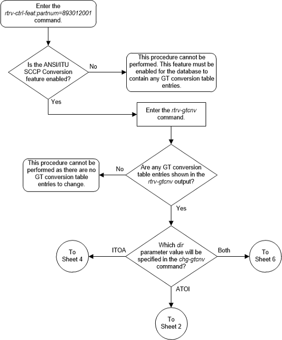
Figure 2-161 Change a GT Conversion Table Entry - Sheet 2 of 7
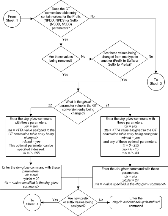
Figure 2-162 Change a GT Conversion Table Entry - Sheet 3 of 7
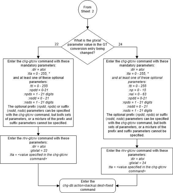
Figure 2-163 Change a GT Conversion Table Entry - Sheet 4 of 7
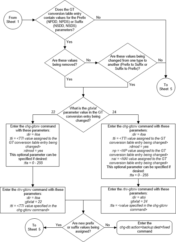
Figure 2-164 Change a GT Conversion Table Entry - Sheet 5 of 7
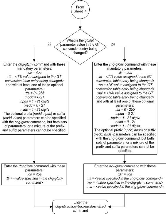
Figure 2-165 Change a GT Conversion Table Entry - Sheet 6 of 7
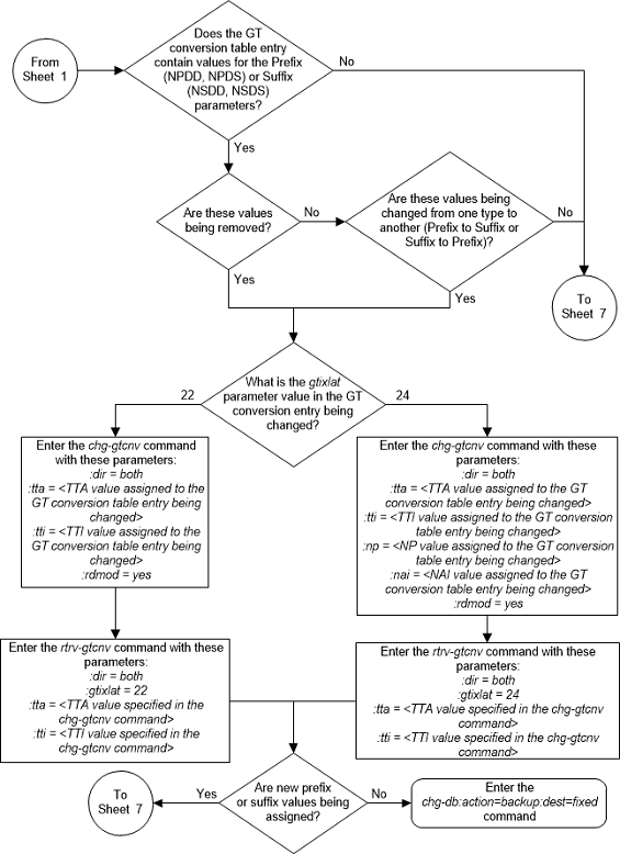
Figure 2-166 Change a GT Conversion Table Entry - Sheet 7 of 7
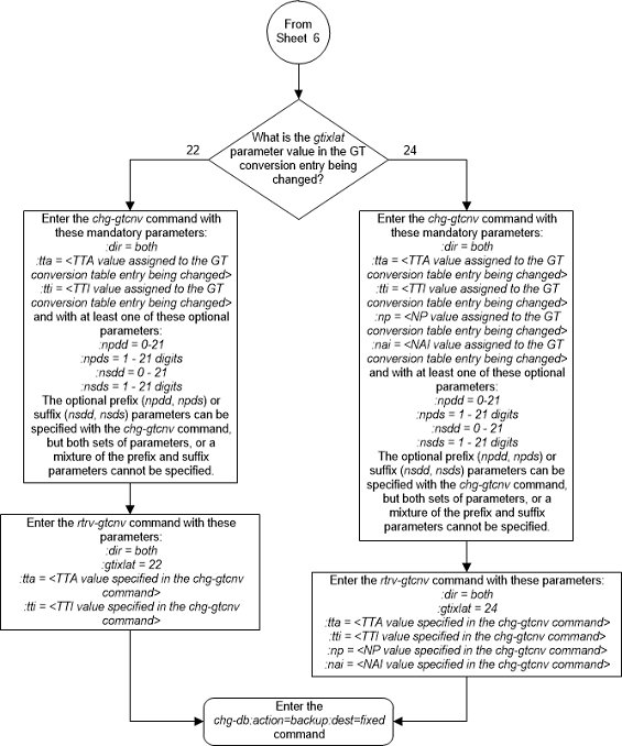
Changing the ANSI/ITU SCCP Conversion Options
This procedure is used to change the options used for the
ANSI/ITU SCCP Conversion feature using the
chg-stpopts command. The options are:
:cnvcgda – The CGPA point
code in ANSI SCCP messages are discarded if the point code or alias point code
of the destination network type is not defined.
:cnvcgdi – The CGPA point
code in ITU-I SCCP messages are discarded if the point code or alias point code
of the destination network type is not defined.
:cnvcgdn – The CGPA point
code in ITU-N SCCP messages are discarded if the point code or alias point code
of the destination network type is not defined.
:cnvcgdn24 – The CGPA
point code in ITU-N24 SCCP messages are discarded if the point code or alias
point code of the destination network type is not defined.
:cnvclgitu – Enables or disables ITU-X
to ITU-Y SCCP CGPA Conversion.
:gtcnvdflt – SCCP
messages are routed using system defaults when an appropriate entry is not
found in the Default GT Conversion Table.
The values for each of these parameters, shown in the
rtrv-stpopts output, is either
yes or
no. The system default values for these
parameters is
no.
These parameters of the
chg-stpopts command are optional. For
any parameters not specified with the
chg-stpopts command, the values for
these parameters are not changed.
The current values for these parameters are shown in the
CNVCGDA,
CNVCGDI,
CNVCGDN,
CNVCGDN24, and
GTCNVDFLT fields in the output of the
rtrv-stpopts command.
The ANSI/ITU SCCP Conversion Feature must be enabled to
change these parameter values with the
chg-stpopts command. The
CNVCGDA,
CNVCGDI,
CNVCGDN,
CNVCGDN24, and
GTCNVDFLT fields in the output of the
rtrv-stpopts command are shown when the
ANSI/ITU SCCP Conversion feature is enabled. If the
CNVCGDA,
CNVCGDI,
CNVCGDN,
CNVCGDN24, and
GTCNVDFLT fields are not shown in the
output of the
rtrv-stpopts command, perform the
Activating the ANSI/ITU SCCP Conversion Feature
procedure to enabled the ANSI/ITU SCCP Conversion feature.
Note:
The ANSI/ITU SCCP Conversion feature can only be permanently enabled.Note:
If the value of theCNVCGDA,
CNVCGDI, or
CNVCGDN value in the
rtrv-stpopts output is
no when this procedure is completed,
and the calling party address of the MSU cannot be converted when the MSU is
processed, then the MSU is discarded.
Figure 2-167 Change the ANSI/ITU SCCP Conversion Options
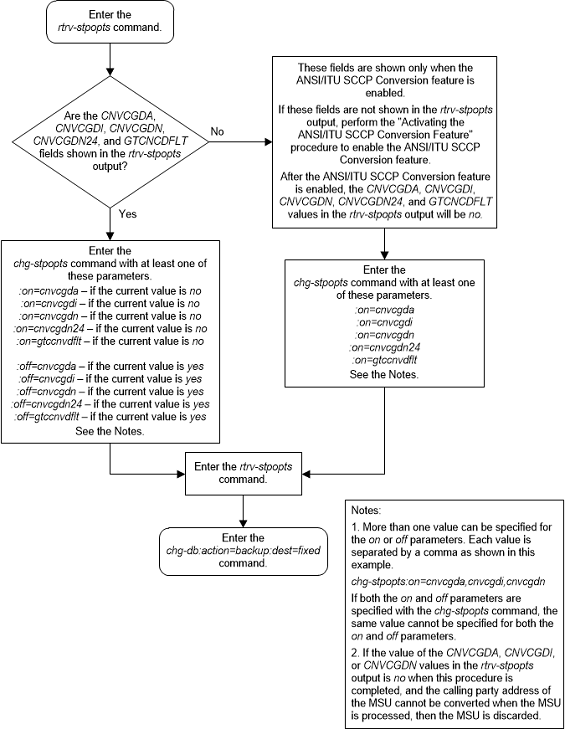
Changing SCCP Class 1 Sequencing Option
This procedure is used to change the option for
sequencing UDT/XUDT Class 1 messages using the
chg-sccpopts command and the
class1seq parameter. The
class1seq parameter has two values
on and
off.
When the
class1seq parameter value is
on, UDT/XUDT Class 1 messages are
delivered to the remote node in the order in which they were received (in
sequence). Load sharing of these messages is performed in the dominant mode,
overriding the load sharing configuration in the MAP and MRN tables.
Delivering the UDT/XUDT Class 1 ITU messages in sequence
is guaranteed only if the
randsls parameter value of the
chg-stpopts command is either
off or
class0. If you wish to guarantee
delivering these messages in sequence, the
class1seq=on and the
randsls=all parameters should not be
used together in the EAGLE. The value of the
randsls parameter is shown in the
rtrv-stpopts command.
When the
class1seq parameter value is
off, load sharing of the UDT/XUDT Class
1 messages is performed using the load sharing configuration in the MAP and MRN
tables. The delivery of the UDT/XUDT Class 1 messages in sequence is not
guaranteed.
Figure 2-168 Change SCCP Class 1 Sequencing Option - Sheet 1 of 2
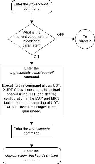
Figure 2-169 Change SCCP Class 1 Sequencing Option - Sheet 2 of 2
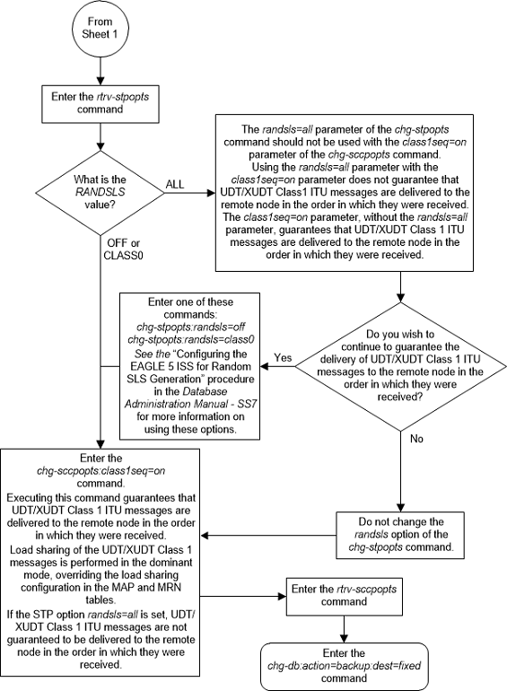
Changing the SCCP Alarm Thresholds
This procedure is used to change the SCCP alarm
thresholds using the
chg-th-alm command and these
parameters.
:sccptpscap – The
percentage for the SCCP load capacity (TPS) threshold alarm, from 0 to 100 and
is shown in the
SCCP TPS Threshold field of the
rtrv-th-alm output and in the
System TPS Alarm Threshold field in the
rept-stat-sccp output. The system
default value is 80. When this threshold is exceeded, UAM 330 is generated.
:sccpcalcmthd – The
calculation method used for determining if the SCCP load capacity (TPS)
threshold alarm level has been exceeded. This parameter contains these values:
-
N– All in-service normal cards are used in the SCCP load capacity (TPS) threshold alarm level calculation. -
NPLUS1– All in-service normal cards minus one of the in-service normal card with the highest TPS capacity are used in the SCCP load capacity (TPS) threshold alarm level calculation.
The system default value is
N.
The value of this parameter is shown in the
SCCP Calculation Method field of the
rtrv-th-alm output and in the
System SCCP Capacity Calc. Method field
in the
rept-stat-sccp output.
The service modules that can be used are SMs and
E5-SM4Gs. Each type of service module supports a certain number of transactions
per second (TPS), SMs - 1700, and E5-SM4G - 1700 or 5000 if the E5-SM4G
Throughput Capacity feature is enabled. If the
sccpcalcmthd=n parameter is specified,
the value in the
System SCCP Capacity Calc. Method field
in the
rept-stat-sccp output is the sum of the
TPS ratings of all the in-service normal service modules, shown with the entry
IS-NR in the
PST column in the
rept-stat-sccp output.
If the
sccpcalcmthd=nplus1 parameter is
specified, the value in the
System SCCP Capacity Calc. Method field
in the
rept-stat-sccp output is the sum of the
TPS ratings of all the in-service normal service modules, shown with the entry
IS-NR in the
PST column in the
rept-stat-sccp output, minus the TPS
rating of the highest rated in-service normal card. If the EAGLE contains only
SMs, or only E5-SM4Gs as service modules, then the TPS rating of one of the SM
or SLIC cards, as applicable, is subtracted from the sum of the TPS ratings of
all the in-service normal service modules. If the EAGLE contains SMs or SLIC,
then the TPS rating of one of the cards is subtracted from the sum of the TPS
ratings of all the in-service normal service modules.
:gttservl1 – The
percentage of the SCCP GTT service errors, shown in the
FAIL RATIO column for the
GTT row of the
TOTAL SERVICE STATISTICS: section of
the
rept-stat-sccp output, from 1 to 100,
that when exceeded, generates major alarm UAM 0452. The system default value is
10.
:gttservl2 – The
percentage of the SCCP GTT service errors, shown in the
FAIL RATIO column for the
GTT row of the
TOTAL SERVICE STATISTICS: section of
the
rept-stat-sccp output, from 1 to 100,
that when exceeded, generates critical alarm UAM 0453. The system default value
is 20.
Note:
After thechg-th-alm command is performed, the
gttservl2 parameter value must be
greater than the
gttservl1 parameter value.
:nongttservl1 – The
percentage of the SCCP non-GTT service errors (for example, GPORT, GFLEX, EIR,
etc.), shown in the
FAIL RATIO column for the rows other
than
GTT in the
TOTAL SERVICE STATISTICS: section of
the
rept-stat-sccp output, from 1 to 100,
that when exceeded, generates major alarm UAM 0452. The system default value is
10.
:nongttservl2 – The
percentage of the SCCP non-GTT service errors (for example, GPORT, GFLEX, EIR,
etc.), shown in the
FAIL RATIO column for the rows other
than
GTT in the
TOTAL SERVICE STATISTICS: section of
the
rept-stat-sccp output, from 1 to 100,
that when exceeded, generates critical alarm UAM 0453. The system default value
is 20.
Note:
After thechg-th-alm command is performed, the
nongttservl2 parameter value must be
greater than the
nongttservl1 parameter value.
:sccpthlv1intvl - The
number of minutes, from 0 to 1440, during which the SCCP threshold level 1
alarm (UAM 0452) cannot be raised more than once. The system default value is
0.
:sccpthlv2intvl - The
number of minutes, from 0 to 1440, during which the SCCP threshold level 2
alarm (UAM 0453) cannot be raised more than once. The system default value is
0.
Note:
After thechg-th-alm command is performed, the
sccpthlv2intvl parameter value must be
greater than the
sccpthlv1intvl parameter value.
For more information on these alarms, refer to Unsolicited Alarm and Information Messages Reference.
The
chg-th-alm command contains other
optional parameters. These parameters are not shown here because they are not
necessary to provision the SCCP alarm thresholds. These parameters are
explained in more detail in
Commands User's Guide.
Figure 2-170 Change the SCCP Alarm Thresholds
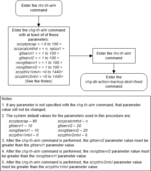
Changing the Transaction-Based GTT Load Sharing Options
This procedure is used to change the options for
performing Transaction-Based GTT Load Sharing using the
chg-sccpopts command and with these
parameters:
:tgtt0 – enable or
disable Transaction-Based GTT Load Sharing for SCCP Class 0 UDT, UDTS, XUDT, or
XUDTS messages. The values for this parameter are:
udt– Transaction-Based GTT Load Sharing is performed for Class 0 UDT or UDTS messages.xudt– Transaction-Based GTT Load Sharing is performed for Class 0 XUDT or XUDTS messages.both– Transaction-Based GTT Load Sharing is performed for Class 0 UDT, UDTS. XUDT and XUDTS messages.none– Transaction-Based GTT Load Sharing is not performed for SCCP Class 0 messages.
:tgtt1 – enable or
disable Transaction-Based GTT Load Sharing for SCCP Class 1 UDT, UDTS, XUDT, or
XUDTS messages. The values for this parameter are:
udt– Transaction-Based GTT Load Sharing is performed for Class 1 UDT or UDTS messages.xudt– Transaction-Based GTT Load Sharing is performed for Class 1 XUDT or XUDTS messages.both– Transaction-Based GTT Load Sharing is performed for Class 1 UDT, UDTS, XUDT and XUDTS messages.none– Transaction-Based GTT Load Sharing is not performed for SCCP Class 1 messages.
:tgttudtkey – the
Transaction Parameter for the incoming UDT or UDTS messages. The values for
this parameter are:
mtp– Transaction-Based GTT Load Sharing is performed on the MTP parameter for UDT and UDTS messages.sccp– Transaction-Based GTT Load Sharing is performed on the SCCP parameter for UDT and UDTS messages.tcap– Transaction-Based GTT Load Sharing is performed on the TCAP parameter for UDT and UDTS messages.enhmtp– Transaction-Based GTT Load Sharing is performed using the enhanced MTP algorithm for UDT and UDTS messages.
:tgttxudtkey – the
Transaction Parameter for the incoming XUDT or XUDTS messages. The values for
this parameter are:
mtp– Transaction-Based GTT Load Sharing is performed on the MTP parameter for XUDT and XUDTS messages.sccp– Transaction-Based GTT Load Sharing is performed on the SCCP parameter for XUDT and XUDTS messages.enhmtp– Transaction-Based GTT Load Sharing is performed using the enhanced MTP algorithm for XUDT and XUDTS messages.
The Transaction-Based GTT Load Sharing feature must be
enabled to change these parameter values with the
chg-sccpopts command. The
tggt0,
tggt1,
tgttudtkey, and
tgttxudtkey fields in the output of the
rtrv-sccpopts command are shown when
the Transaction-Based GTT Load Sharing feature is enabled. If the
tggt0,
tggt1,
tgttudtkey, and
tgttxudtkey fields are not shown in the
output of the
rtrv-sccpopts command, perform the
Activating the Transaction-Based GTT Load Sharing Feature
procedure to enable the Transaction-Based GTT Load Sharing feature.
When the Transaction-Based GTT Load Sharing feature is
enabled, these values for the
tggt0,
tggt1,
tgttudtkey, and
tgttxudtkey fields are shown in the
rtrv-sccpopts output:
tggt0– nonetggt1– nonetgttudtkey– mtptgttxudtkey– mtp.
If any parameter is not specified with the
chg-sccpopts command, that parameter
value will not be changed.
If the value
both is specified for the
tggt0 or
tggt1 parameters, the entry
UDT,XUDT is shown in the
tggt0 or
tggt1 fields of the
rtrv-sccpopts output.
For more information on the Transaction-Based GTT Load Sharing feature, refer to the Transaction-Based GTT Load Sharing section.
Figure 2-171 Change the Transaction-Based GTT Load Sharing Options
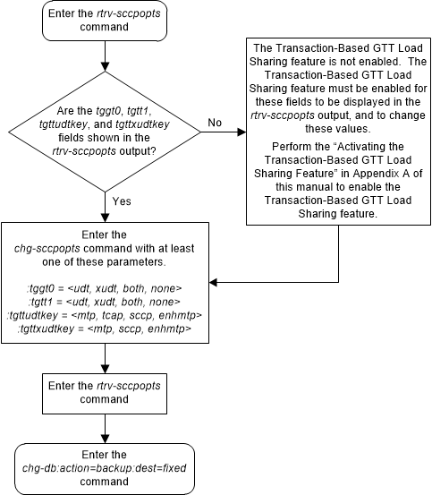
Adding a Loopset
This procedure is used to add a loopset to the database
using the
ent-loopset command.
The
ent-loopset command uses these
parameters.
:name - The name of the
loopset. The loopset name can contain up to 8 characters, with the first
character being a letter.
:pc1/pc1a/pc1i/pc1n/pc1n24 - The point codes assigned
to the specified loopset, either an ANSI point (pc1/pc1a), ITU-1 or ITU-1 spare point (pc1i), a 14-bit ITU-N or 14-bit ITU-N spare point code
(pc1n), or a 24-bit ITU-N (pc1n24) point code.
Note:
See Chapter 2, Configuring Destination Tables in Database Administration - SS7 User's Guide for a definition of the point code types that are used on the EAGLE and for the definition of the different formats that can be used for ITU national point codes.:mode - Mode of
operation. Can be notify or discard. This is an optional parameter that
specifies whether the message is discarded when an SCCP loop is detected. The
"Notify only" mode of operation generates UIMs but not actually discard the
message, which allows a user to capture and verify messages. However, the
"Discard" mode of operation generates the UIMs and also discard the MSUs.
To add a loopset to the database, the SCCP Loop
Detection feature must be enabled. The
rtrv-ctrl-feat command output shows
whether or not the SCCP Loop Detection feature is enabled. If the SCCP Loop
Detection feature is not enabled, perform the
Activating the SCCP Loop Detection Feature
procedure to enable this feature.
All the point codes specified with the
pc1/pc1a/pc1i/pc1n/pc1n24 parameter
must be the same type of point code. The point code values are separated by
commas with no spaces between the commas and the point code values as shown in
the example
pc1=002-002-002,003-003-003,004-004-004. This example
specified three ANSI point codes for the loopset.
A maximum of twelve point codes can be assigned to a single loopset. However, this procedure can be used to assign a maximum of six point codes to a single loopset. If you wish to add more point codes to the loopset entries, perform the Changing the Attributes of a Loopset procedure.
A maximum of 1000 loopsets can be assigned to a loopset
database. If adding the new loopset entries exceed the maximum capacity of the
loopset table displayed in the
rtrv-loopset command output, entries
in the loopset table must be removed to ensure that the new loopset entries can
be added. Perform the
Removing a Loopset
procedure to remove the required number of loopset entries
Figure 2-172 Add a Loopset to the Database - Sheet 1 of 2
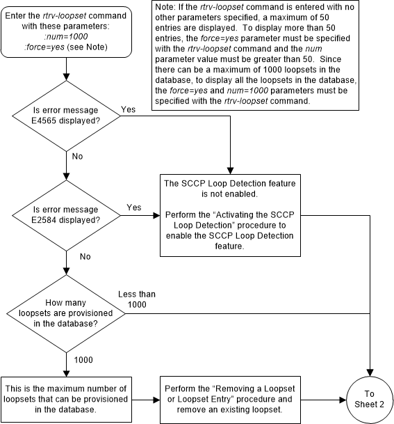
Figure 2-173 Add a Loopset to the Database - Sheet 2 of 2
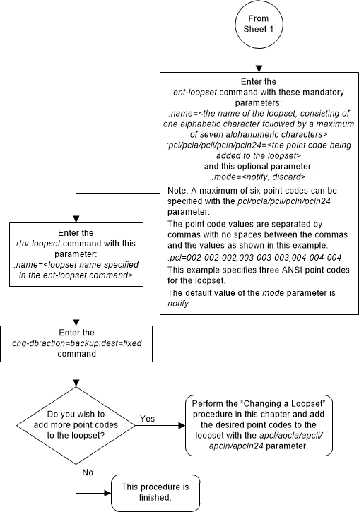
Removing a Loopset
This procedure is used to remove an entire loopset from
the database or a specific point code in a loopset using the
dlt-loopset command.
The
dlt-loopset command uses these
parameter.
:name - The name of the
loopset being removed, shown in the
rtrv-loopset output.
:force – This parameter
has two values, yes or no. The value yes allows the point code in the loopset
to be removed if the loopset is assigned to entries in either the
rtrv-gtt or
rtrv-gta outputs. The value no
requires that any references to the loopset must be removed from the GTT or GTA
entries before the loopset or the point code in the loopset can be removed.
Perform one of these procedures to remove the reference to the loopset,
depending on whether or not the EGTT feature is on. The status of the EGTT
feature is shown in the
rtrv-feat command output.
- If the EGTT feature is not on – Enter the
rtrv-gttcommand to verify the loopset references. Perform the Changing a Global Title Translation procedure and change the loopset reference toNONEor to another loopset name, or remove the global title translation by performing the Removing a Global Title Translation procedure. - If the EGTT feature is on – Enter the
rtrv-gtacommand to verify the loopset references. Perform Changing Global Title Address Information and change the loopset reference toNONEor to another loopset name, or remove the entry by performing the Removing Global Title Address Information procedure.
:pcl/pcla/pcli/pcln/pcln24 – The point code, either an
ANSI point code (pcl/pcla), ITU-I or ITU-I
spare point code (pcli), a 14-bit ITU-N or
14-bit ITU-N spare point code (pcln), or a
24-bit ITU-N (pcln24) point code, that is
assigned to the loopset and shown in the
rtrv-loopset output.
If the
dlt-loopset command is specified with
the
name and
pcl/pcla/pcli/ pcln/pcln24 parameter,
the specified point code is removed from the loopset.
If the
dlt-loopset command is specified with
the
name parameter and without the
pcl/pcla/pcli/pcln/pcln24 parameter,
the entire loopset is removed from the database.
Figure 2-174 Remove a Loopset - Sheet 1 of 3
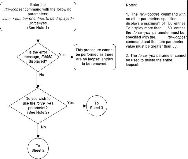
Figure 2-175 Remove a Loopset - Sheet 2 of 3
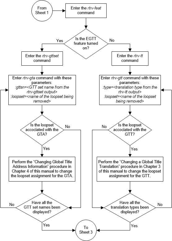
Figure 2-176 Remove a Loopset - Sheet 3 of 3
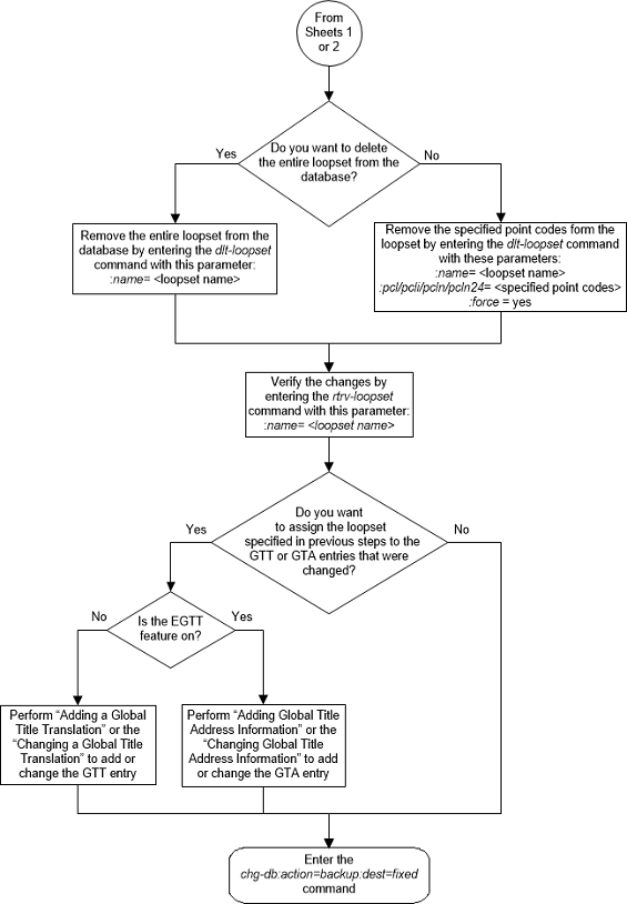
Changing the Attributes of a Loopset
This procedure is used to modify a loopset in the
following ways using the
chg-loopset command.
- Change the mode of operation
- Replace all the point codes
- Replace a specific point code
- Replace two specific point codes
- Append additional point codes
The
chg-loopset command uses these
parameters.
:name – The name of the
loopset to be modified, shown in the rtrv-loopset output.
:force – This parameter
has two values, yes or no. The value yes allows the attributes of a loopset to
be changed if the loopset is assigned to entries in either the
rtrv-gtt or
rtrv-gta outputs. The value no
requires that references to the loopset must be removed from the GTT or GTA
entries before the attributes of the loopset are changed. Perform one of these
procedures to remove a reference to the loopset, depending on whether or not
the EGTT feature is on. The status of the EGTT feature is shown in the
rtrv-feat command output.
- If the EGTT feature is not on – Enter the
rtrv-gttcommand to verify the loopset references. Perform the Changing a Global Title Translation procedure and change the loopset reference toNONEor to another loopset name, or remove the global title translation by performing the Removing a Global Title Translation procedure. - If the EGTT feature is on – Enter the
rtrv-gtacommand to verify the loopset references. Perform Changing Global Title Address Information and change the loopset reference toNONEor to another loopset name, or remove the entry by performing the Removing Global Title Address Information procedure.
:pcl/pcla/pcli/pcln/pcln24 – The point code, either an ANSI point
code (pcl/pcla), ITU-I or ITU-I spare point
code (pcli), a 14-bit ITU-N or 14-bit ITU-N
spare point code (pcln), or a 24-bit ITU-N
(pcln24) point code, assigned to the loopset
shown in the
rtrv-loopset output that is to be
replaced by a new point code. This point code is the first or the only point
code that can be replaced when the
chg-loopset command is used to replace
two specific point codes or a single point code.
:pc2/pc2a/pc2i/pc2n/pc2n24 – The point code, either an
ANSI point code (pc2/pc2a), ITU-I or ITU-I
spare point code (pc2i), a 14-bit ITU-N or
14-bit ITU-N spare point code (pc2n), or a
24-bit ITU-N (pc2n24) point code, assigned to
the loopset shown in the
rtrv-loopset output that is to be
replaced by a new point code. This point code is the second point code that can
be replaced when the
chg-loopset command is used to replace
two specific point codes.
:rpcl/rpcla/rpcli/rpcln/rpcln24 – The point code,
either an ANSI point code (rpcl/rpcla), ITU-I
or ITU-I spare point code (rpcli), a 14-bit
ITU-N or 14-bit ITU-N spare point code (rpcln), or a 24-bit ITU-N (rpcln24) point code, that is used to simultaneously
replace all the point code(s) assigned to the loopset shown in the
rtrv-loopset output.
:npcl/npcla/npcli/npcln/npcln24 – The point code, either an ANSI
point code (npcl/npcla), ITU-I or ITU-I spare
point code (npcli), a 14-bit ITU-N or 14-bit
ITU-N spare point code (npcln), or a 24-bit
ITU-N (npcln24) point code that replaces the
first or the only specified point code when the
chg-loopset command is used to replace
two specific point codes or a single point code.
:npc2/npc2a/npc2i/npc2n/npc2n24 – The point code, either an ANSI
point code (npc2/npc2a), ITU-I or ITU-I spare
point code (npc2i), a 14-bit ITU-N or 14-bit
ITU-N spare point code (npc2n), or a 24-bit
ITU-N (npc2n24) point code that replaces the
second specified point code when the
chg-loopset command is used to replace
two specific point codes.
:apcl/apcla/apcli/apcln/apcln24 – The point code,
either an ANSI point code (npcl/npcla), ITU-I
or ITU-I spare point code (npcli), a 14-bit
ITU-N or 14-bit ITU-N spare point code (npcln), or a 24-bit ITU-N (npcln24) point code that can be appended to the set of
point codes assigned to the loopset shown in the
rtrv-loopset output.
:mode – The mode of
operation of the SCCP Loop Detection feature. This parameter can have either of
the two values Notify and Discard.
Figure 2-177 Change the Attributes of a Loopset - Sheet 1 of 3
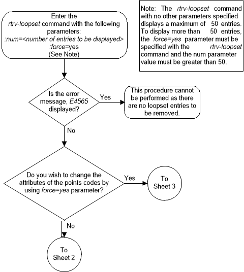
Figure 2-178 Change the Attributes of a Loopset - Sheet 2 of 3
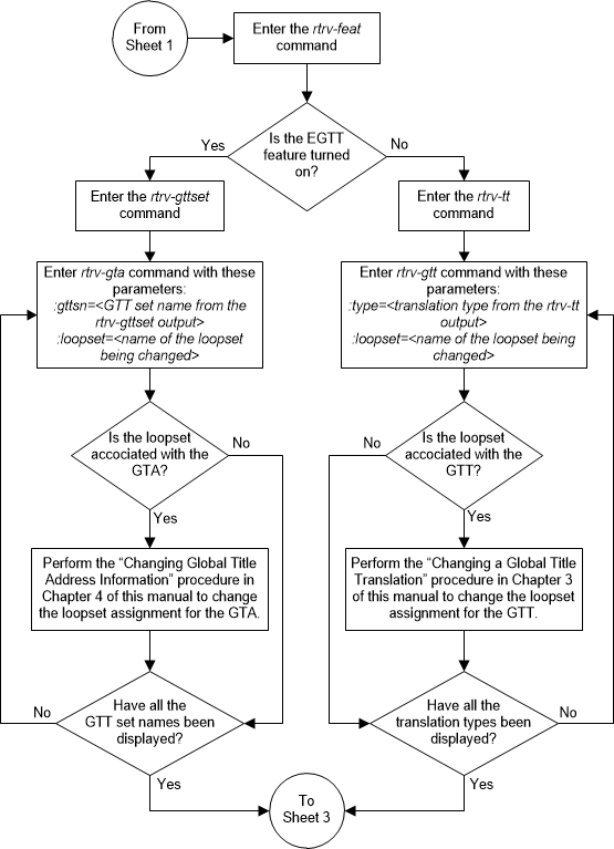
Figure 2-179 Change the Attributes of a Loopset - Sheet 3 of 3
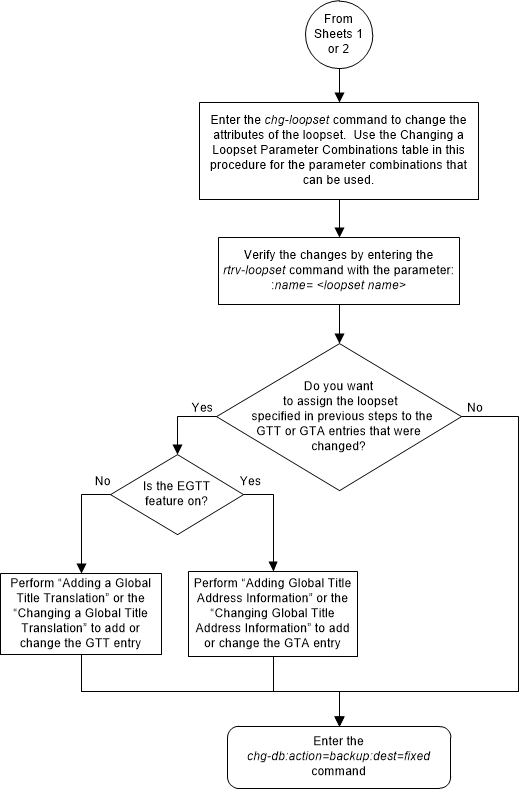
Configuring the ANSI to ITU-N SCCP Conversion Option
This procedure is used to set the value of the called
party/calling party address Reserved for National Use bit that is used during
SCCP conversion when global title translation routes the message to the ITU
national network. The called/calling party address Reserved for National Use
bit is set using the
chg-sccpopts command and with this
parameter.
:cnvainat – the value
of the called party/calling party address Reserved for National Use bit used
during SCCP conversion when the MSU is routed to the ITU national network. The
values for this parameter are:
0– the Reserved for National Use bit is not reserved for national use.1– the Reserved for National Use bit is reserved for national use.
The system default value for this parameter is 1.
The ANSI/ITU SCCP Conversion feature must be enabled and
turned on to change this parameter value with the
chg-sccpopts command. The
CNVAINAT field in the output of the
rtrv-sccpopts command output is shown
when the ANSI/ITU SCCP Conversion feature is enabled and turned on. If the
CNVAINAT field is not shown in the
output of the
rtrv-sccpopts command output, perform
the
Activating the ANSI/ITU SCCP Conversion Feature
procedure to enable the ANSI/ITU SCCP Conversion feature.
If any parameter is not specified with the
chg-sccpopts command, that parameter
value will not be changed.
For more information on the ANSI/ITU SCCP Conversion feature, refer to the ANSI/ITU SCCP Conversion Feature section.
Figure 2-180 Configure the ANSI to ITU-N SCCP Conversion Option
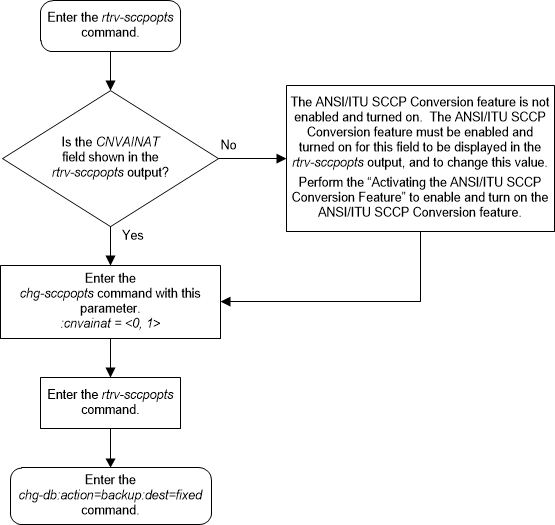
Configuring a SCCP Test Message
tst-msg command to debug the global
title translation rules for these features.
- Origin-Based SCCP Routing
- Flexible Linkset Optional Based Routing
- TCAP Opcode Based Routing
The data for an SCCP test message is configured using
the
chg-sccp-msg command.
Table 2-61
shows the parameters and their combinations that are used with the
chg-sccp-msg command.
To perform this procedure, the GTT feature must be
turned on. This can be verified by entering the
rtrv-feat
command. If the
gtt value is
on, the GTT feature is on. If the GTT
feature is not on, perform the
Adding a Service Module
procedure to turn the GTT feature on and make sure the correct hardware is
installed and provisioned.
If any parameter is not specified with the
chg-sccp-msg command, that parameter
value will not be changed.
Table 2-61 SCCP Test Message Parameter Combinations
| Flexible Linkset Optional Based Routing Enable and Turned On and TCAP Opcode Based Routing feature Enable and Turned On |
|---|
| Mandatory Parameter |
| :msgn - 1 to 10 |
| Optional Parameters (See Note 1) |
| :active - specifies whether the SCCP message should be sent to the network card for processing - yes, no. Default value - yes |
| :cdgta - the called party address for the SCCP message - 1 - 21 digits or 1 - 21 hexadecimal digits. Default value - 1234567890 |
| :cdgti - the called party global title indicator for the SCCP message - 2 or 4. Default value - 2 (See Note 2) |
| :cdnai - the called party nature of address indicator for the SCCP message - See Note 3. Default value - sub |
| :cdnaiv - the called party nature of address indicator value for the SCCP message - See Note 3. Default value - 1 |
| :cdnp - the called party numbering plan for the SCCP message - See Note 4. Default value - e164 |
| :cdnpv - the called party numbering plan value for the SCCP message - See Note 4. Default value - 1 |
| :cdpc/cdpci/cdpcn/cdpcn24 - the called party address point code. Default value - ANSI point code 010-010-010 (See Note 5) |
| :cdssn - the called party subsystem number for the SCCP message - 0 - 255, none. Default value - 6 |
| :cdtt - the called party translation type for the SCCP message - 0 - 255. Default value - 0 |
| :cggta - the calling party address for the SCCP message - 1 - 21 digits or 1 - 21 hexadecimal digits. Default value - 1234567890 |
| :cggti - the calling party global title indicator for the SCCP message -2 or 4. Default value - 2 (See Note 2) |
| :cgnai - the calling party nature of address indicator for the SCCP message - See Note 6. Default value - sub |
| :cgnaiv - the calling party nature of address indicator value for the SCCP message - See Note 6. Default value - 1 |
| :cgnp - the calling party numbering plan for the SCCP message - See Note 7. Default value - e164 |
| :cgnpv - the calling party numbering plan value for the SCCP message - See Note 7. Default value - 1 |
| :cgpc/cgpci/cgpcn/cgpcn24 - the calling party address point code. Default value - ANSI point code 020-020-020 (See Note 5) |
| :cgssn - the calling party subsystem number for the SCCP message -0 - 255, none. Default value - 8 |
| :cgtt - the calling party translation type for the SCCP message - 0 - 255. Default value - 0 |
| :eaglegen - specifies whether the message is an EAGLE generated message - no, yes. Default value - no |
:lsn - the name of the incoming linkset for the SCCP
message. The linkset must be shown in the
rtrv-ls output. Default value - No lsn value
specified
|
| :opc/opci/opcn/opcn24 - the originating point code. Default value - ANSI point code 010-010-010 (See Note 5) |
| :tcapacn - a maximum of 7 subfields containing the numbers 0 to 255 separated by dash (for example, 1-202-33-104-54-26-007), none. The value none means there is no ITU TCAP ACN field in the incoming message. Default value - none |
| :tcapfamily - 0 - 255, none. The value none means there is no ANSI TCAP FAMILY field in the incoming message. Default value - none |
| :tcapopcode - 0 - 255, none. The value none means there is no TCAP OPCODE field in the incoming message. Default value - none |
| :tcappkg - See Notes 8 and 9. Default value - invalid |
| :tcappkgv - 0 - 255. Default value - 0 (See Note 8) |
| :dpc/dpca/dpci/dpcn/dpcn24 - the destination point code. Default value - ANSI point code 020-020-020 (See Note 5) |
| :selid - 0 - 65534 - Default value - no value specified |
Notes:
|
Table 2-62 NAIV/NAI Mapping
| NAIV | NAI | Description |
|---|---|---|
| 0 | -- | Unknown |
| 1 | Sub | Subscriber Number |
| 2 | Rsvd | Reserved for national use |
| 3 | Natl | National significant number |
| 4 | Intl | International number |
| 5-127 | -- | Spare |
Table 2-63 NPV/NP Mapping
| NPV | NP | Description |
|---|---|---|
| 0 | -- | Unknown |
| 1 | E164 | ISDN/telephony numbering plan |
| 2 | Generic | Generic numbering plan |
| 3 | X121 | Data numbering plan |
| 4 | F69 | Telex numbering plan |
| 5 | E210 | Maritime mobile numbering plan |
| 6 | E212 | Land mobile numbering plan |
| 7 | E214 | ISDN/mobile numbering plan |
| 8 | Private | Private network or network-specific numbering plan |
| 9-15 | -- | Spare |
Figure 2-181 Configure a SCCP Test Message
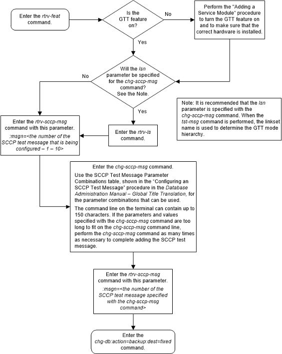
Adding Global Title Modification Information
This procedure is used to add global title (GT)
modification information to the database. The GT modification information is
used to modify information in an MSU during the global title translation
process when the MSU requires further global title translation. The GT
modification information is added to the database using the
ent-gtmod command with these
parameters.
:gtmodid – The name of
the GT modification identifier
:cgpassn – The
subsystem number in the calling party address
:ntt – The new
translation type
:nnp – The new
numbering plan
:nnai – The new nature
of address indicator
:npdd – The number of
digits to be deleted from the beginning of the Global Title Address digits (the
prefix digits)
:npds – The digits that
are being substituted for the prefix digits
:nsdd – The number of
digits to be deleted from the end of the Global Title Address digits (the
suffix digits)
:nsds – The digits that
are being substituted for the suffix digits
:ngti – The new GT
indicator value
on=gt0fill - if the
last value of the global title address is zero (0), it is treated or as a
filler during the GT modification process.
off=gt0fill - if the
last value of the global title address is zero (0), it is treated as a valid
digit during the GT modification process.
precd - specifies
whether the prefix (npds/npdd parameter values) or suffix (nsds/nsdd parameter
values) takes precedence while modifying the received Global Title Address.
The values for these parameters and the rules for using these parameters are shown in Table 2-64.
One of the Advanced GT Modification features must be
enabled to add GT modification information to the database. The status of the
Advanced GT Modification features is shown the
rtrv-ctrl-feat command output. The
part numbers of the Advanced GT Modification features are shown in
2.
Figure 2-182 Add Global Title Modification Information - Sheet 1 of 2
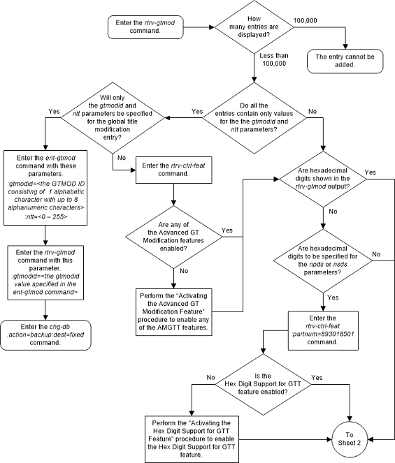
Figure 2-183 Add Global Title Modification Information - Sheet 2 of 2
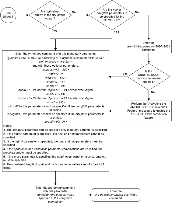
Removing Global Title Modification Information
This procedure is used to remove existing global title
(GT) modification information from the database using the
dlt-gtmod command and with this
parameter.
:gtmodid –
:gtmodid – The name of the GT
modification identifier that contains the GT modification that is being
removed.
REFCNT field of the
rtrv-gtmod output. The
REFCNT field is displayed only when
the
on=refcnt parameter is specified with
the
rtrv-gtmod command.
- GTT entities shown in the
rtrv-gttoutput. - GTA entities shown in the
rtrv-gtaoutput. - GTT action entities shown in the
rtrv-gttactoutput.
Figure 2-184 Remove Global Title Modification Information - Sheet 1 of 3
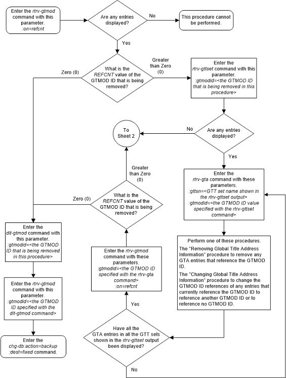
Figure 2-185 Remove Global Title Modification Information - Sheet 2 of 3
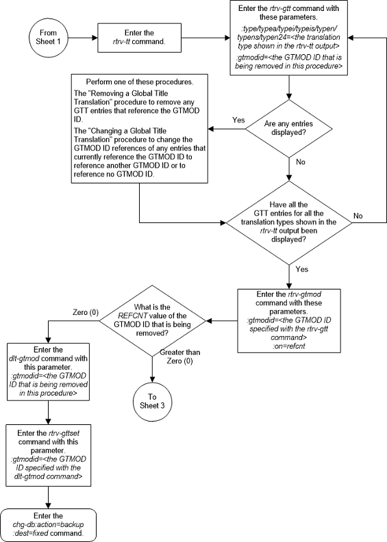
Figure 2-186 Remove Global Title Modification Information - Sheet 3 of 3
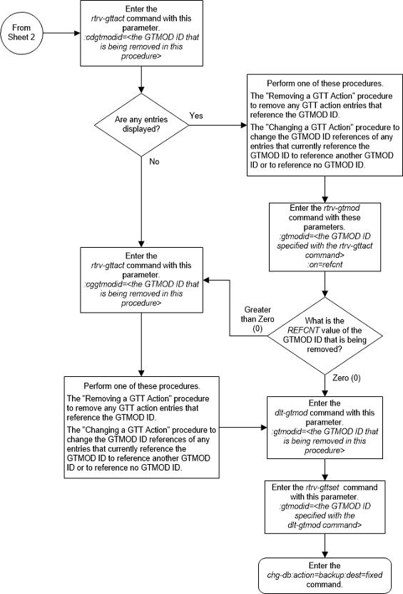
Changing Global Title Modification Information
This procedure is used to change the attributes of
global title (GT) modification information in the database. The GT modification
information is changed using the
chg-gtmod command with these
parameters.
:gtmodid – The current
name of the GT modification identifier
:ngtmodid – The new
name of the GT modification identifier
:cgpassn – The
subsystem number in the calling party address
:ntt – The new
translation type
:nnp – The new
numbering plan
:nnai – The new nature
of address indicator
:npdd – The number of
digits to be deleted from the beginning of the Global Title Address digits (the
prefix digits)
:npds – The digits that
are being substituted for the prefix digits
:nsdd – The number of
digits to be deleted from the end of the Global Title Address digits (the
suffix digits)
:nsds – The digits that
are being substituted for the suffix digits
:ngti – The new GT
indicator value
on=gt0fill - if the
last value of the global title address is zero (0), it is treated or as a
filler during the GT modification process.
off=gt0fill - if the
last value of the global title address is zero (0), it is treated as a valid
digit during the GT modification process.
precd - specifies
whether the prefix (npds/npdd parameter values) or suffix (nsds/nsdd parameter
values) takes precedence while modifying the received Global Title Address.
The values for these parameters and the rules for using these parameters are shown in Table 2-65.
The
nnp,
nnai,
npdd,
npds,
nsdd, and
nsds parameters are used by the
Advanced GT Modification feature to modify the numbering plan, nature of
address indicator, and the prefix digits, the suffix digits, or both the prefix
and suffix digits in the called party address portion of outbound MSUs in
addition to the translation type when the MSU requires further global title
translation and the translation type is to be replaced. Refer to the
Advanced GT Modification Feature
section for more information about the Advanced GT Modification feature.
Being able to change the numbering plan, nature of address indicator, and either the prefix or suffix digits in the called party address portion of outbound MSUs makes the MSU more compatible with the network that the MSU is being sent to and to ensure that the MSU is routed correctly. These changes are made after the global title translation process, but before the MSU is routed to its destination.
To specify a value of 2 or 4 for the
ngti parameter, the ANSI/ITU SCCP
Conversion feature must be enabled. Verify the status of the ANSI/ITU SCCP
Conversion feature with the
rtrv-ctrl-feat
command. Refer to the
ANSI/ITU SCCP Conversion Feature
section for more information about the ANSI/ITU SCCP Conversion feature. If the
ANSI/ITU SCCP Conversion feature is not enabled, perform the
Activating the ANSI/ITU SCCP Conversion Feature
procedure to enable the ANSI/ITU SCCP Conversion feature.
The values specified for the
npds and
nsds parameters can be decimal digits
(0-9) or hexadecimal digits (0-9, a-f, A-F). Hexadecimal digits can be
specified only if the Hex Digit Support for GTT feature is enabled. Verify the
status of the Hex Digit Support for GTT feature with the
rtrv-ctrl-feat
command. Refer to the
Hex Digit Support for GTT
section for more information about the Hex Digit Support for GTT feature. If
the Hex Digit Support for GTT feature is not enabled, perform the
Activating the Hex Digit Support for GTT Feature
procedure to enable the Hex Digit Support for GTT feature.
Figure 2-187 Change Global Title Modification Information - Sheet 1 of 5
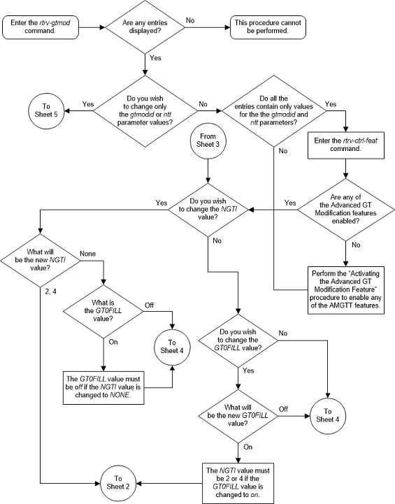
Figure 2-188 Change Global Title Modification Information - Sheet 2 of 5
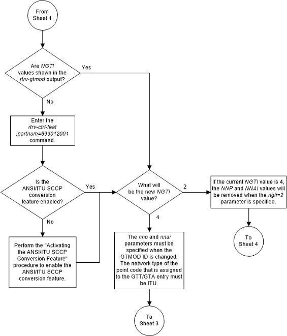
Figure 2-189 Change Global Title Modification Information - Sheet 3 of 5
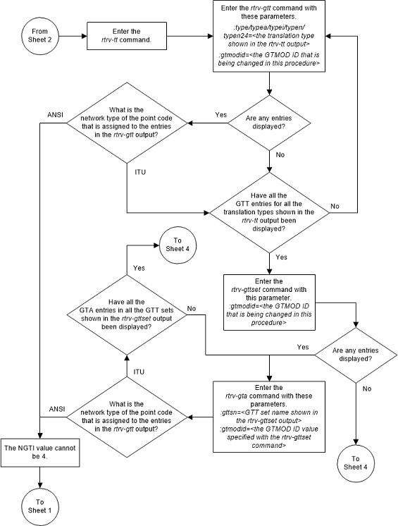
Figure 2-190 Change Global Title Modification Information - Sheet 4 of 5
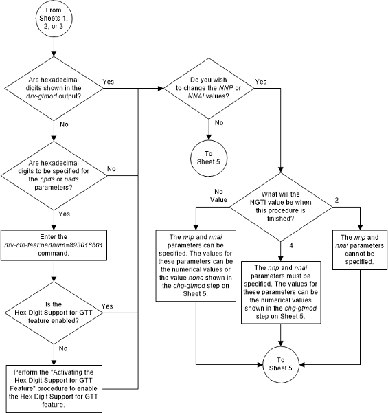
Figure 2-191 Change Global Title Modification Information - Sheet 5 of 5
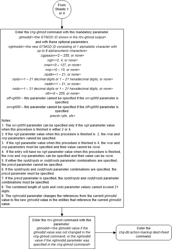
Changing the MTP-Routed GTT Options
This procedure is used to change the MTP-routed GTT
options using the
chg-sccpopts command with these
parameters.
:mtprgtt – This
parameter specifies whether global title translation is performed on an
MTP-routed message and how the message is routed after global title translation
is performed on the message. This parameter has three values.
off- global title translation is not performed on the MTP-routed message.usemtppc- global title translation is performed on the MTP-routed message and is then routed to the original DPC.fullgtt- global title translation is performed on the MTP-routed message and is then routed to the translated DPC.
:mtprgttfallbk – this
parameter specifies whether an MTP-routed message is MTP-routed after global
title translation on the message has failed. This parameter has two values.
mtproute- perform MTP-routing on the message if global title translation on the message fails.gttfail- discard the message if global title translation on the message fails. Send a UDTS if required.
This procedure can be performed only if the MTP Routed
GWS Stop Action feature or the MTP Msgs for SCCP Apps feature is enabled. The
status of these features is shown in the
rtrv-ctrl-feat output.
Figure 2-192 Change the MTP-Routed GTT Options