5 Site Engineering - EAGLE
5.1 Safety and Cautionary Information
DANGER:
At least two people are required to safely move and position the frames.
DANGER:
No commercially AC powered equipment may be used or placed within 7 ft. of –48VDC equipment. This may create a shock or current loop that can be severely hazardous to personnel and equipment.
topple:
Frames with sliding shelves must be securely anchored to the floor and overhead frame racks. Extending a shelf without correctly anchoring the frame can cause it to topple, endangering personnel and damaging equipment.
5.2 Introduction
This chapter contains procedures for preparing the site for the installation of signaling products and is intended for use by personnel involved in planning and executing an installation. This chapter also provides power, environmental, and floor plan requirements relating to that installation.
This chapter covers only those areas unique to Oracle Communications systems and does not cover common telecommunications installation requirements.
5.3 Location
The system is designed to be installed and operated in a central office environment.
Local fire protection codes must be satisfied in the equipment room where the system is to be located.
5.3.1 Space Requirements
This system equipment is housed in 7 foot high, 23 inch wide, floor supported, unequal flange upright frames. Separator panels, and end panels add to the width of multiple frame systems.
The floor area taken up by this system is:
-
1 frame = 30 inches wide by 22 inches deep = 660 square inches (4.6 square feet)
-
2 frames = 62 inches wide by 22 inches deep = 1364 square inches (9.5 square feet)
-
3 frames = 94 inches wide by 22 inches deep = 2068 square inches (14.4 square feet)
-
4 frames = 126 inches wide by 22 inches deep = 2772 square inches (19.3 square feet)
-
5 frames = 158 inches wide by 22 inches deep = 3476 square inches (24.1 square feet)
-
6 frames = 190 inches wide by 22 inches deep = 4180 square inches (29 square feet)
The number of frames required for an installation is described in the Initial Sales Order for that site. The number of frames is determined by the space required by the module population of the system and optional items such as holdover clocks. See the Planning Guide, STP, LNP, and LSMS for information on populating the system.
When planning the installation, be sure to take into account spare module storage, modems, terminals, printers, cross connect panels, and all other items that might require space in a system.
5.3.2 Lighting
Adequate lighting should be provided in the room where the equipment is to be located. Lighting fixtures must be far enough from the equipment and cables to prevent heat damage and to allow safe access to equipment and cables.
5.3.3 Building Requirements
The building requirements for this system are standard telephony industry requirements for equipment installation.
The building must provide a clear, uncluttered route between the loading/receiving dock and the planned system location. In order to move the equipment to the proper location, recommended hall clearance is at least 4.5 feet (1.4 meters) wide by 8 feet (2.4 meters) tall.
Four foot, (1.2 meter) side aisles should be used to allow maneuvering frames into place and provide ample work space around the equipment.
The room selected for system installation should be large enough so the system frames can be at least 2.5 feet (76 cm) from the walls for front and rear access and at least 12 inches (31 cm) for side access.
5.3.4 Earthquake Resistance
All of the configurations are designed to assure the system remains operational during and after an earthquake, even when the system is located on the upper floors of a zone 4 central office.
5.3.5 Environmental Requirements
The environmental conditions for the system must be maintained to the following ambient temperature and humidity specifications:
- Normal operating temperature — +41° F to +104° F, (+5° C to +40° C)
- Maximum rate of temperature change — 15° F, (8° C)/hour
- Normal operating relative humidity — 5% to 85%
- Short-term relative humidity — 5% to 90% (not to exceed 0.024 kg of water per kg of dry air)
- Altitude — 200 feet (60 meters) below to 13,000 feet (3,900 meters) above sea level
Note:
Short-term is a period of not more than 96 consecutive hours and a total of not more than 15 days in one year.Note:
Ambient is to conditions at a location 1.5 m (59 in) above the floor and 400 mm (15.8 in) in front of equipment.Note:
HIPR2 is fully NEBS compliant. However, if ambient temperatures above 40° C are likely, Eagle Fan Trays are recommended to ensure proper airflow to the upper HIPR2 cards in those shelves. See "Hardware Baseline Table" in Release Notes for compatible fan tray part numbers.
5.3.6 Heating Ventilation and Air Condition Requirements
To maintain the required temperature range, Heating, Ventilation, and Air Conditioning (HVAC) equipment should have the capacity to compensate for up to 1230 BTUs/hr for each installed system shelf.
The required HVAC capacity to compensate for a miscellaneous frame varies depending on the customer previously installed equipment. To calculate needed HVAC capacity, determine the wattage of the installed equipment and use the following formula: watts x 3.413 = BTUs/hr.
5.3.7 Floor Loading
It is recommended the floor or raised sub-flooring have a distributed load capacity of no less than 100 pounds per square foot (453 kg/m2). The floor loading is determined by using the following equation:
Total equipment weight/floor area = distributed floor capacity.
Following are the maximum weights of frames:
-
Maximum weight of EAGLE Control or Extension frames: 850 lbs (386 kg).
-
Maximum weight of a four E5-APP-B card frame with six Telco Switches: 500 lbs (226 kg).
See Space Requirements for the floor area of the combined system.
5.3.8 Grounding
The system operates as a digital isolated ground plane system in a central office environment and requires a single connection to the central office ground window. The system’s ground bars and ground cables must provide the sole grounding connection between the entire system and the central office grounding.
The system uses three types of grounding paths:
-
Battery return
-
Frame/chassis ground
-
Logic ground
Non-oxidizing grease will be applied to all lugs terminated on a copper system ground bar. Refer to Figure 5-1.
The power return grounding path is the return path for all –48VDC loads in the system. This path is isolated from other system grounds and connects to the rest of the central office through the –48VDC return connections located on the Fuse and Alarm Panel (FAP) of each frame.
The frame/chassis ground path provides a low impedance connection for all metal parts of the entire system, including the frame, doors, card cages, and end panels. Each frame/chassis connection within the system lineup terminates to the frame and connects to the main ground bar by way of Htaps, #6 American Wire Gauge (AWG) to 1/0 cable.
The logic ground path provides a common voltage reference point between all circuit boards of an system. Each connection terminates to the system ground bar on the control frame.
The frame/chassis and logic ground paths are both noncurrent carrying paths.
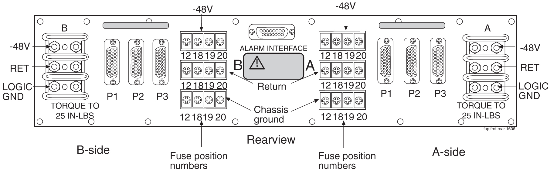
warning:
The power (-48 VDC) and return connections of FAP (P/N 870-0243-08) and (P/N 870-1606-xx) are physically reversed at the input terminal. See Figure 5-1 and Figure 5-2 for wiring information.Figure 5-1 Logic Grounding with FAP (P/N 870-0243-08)
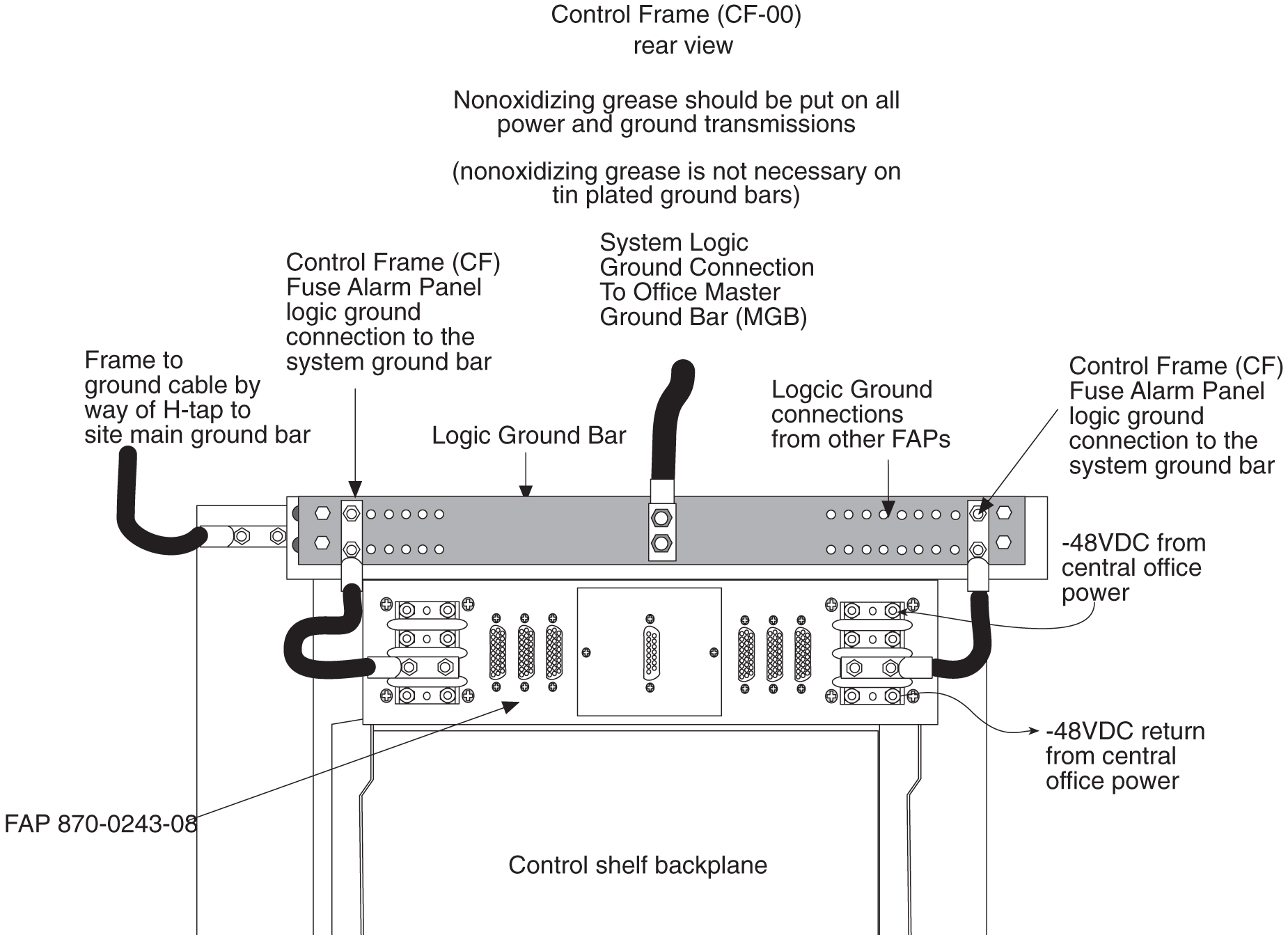
Figure 5-2 Logic Grounding with FAP (P/N 870-1606-xx/870-2320-xx)
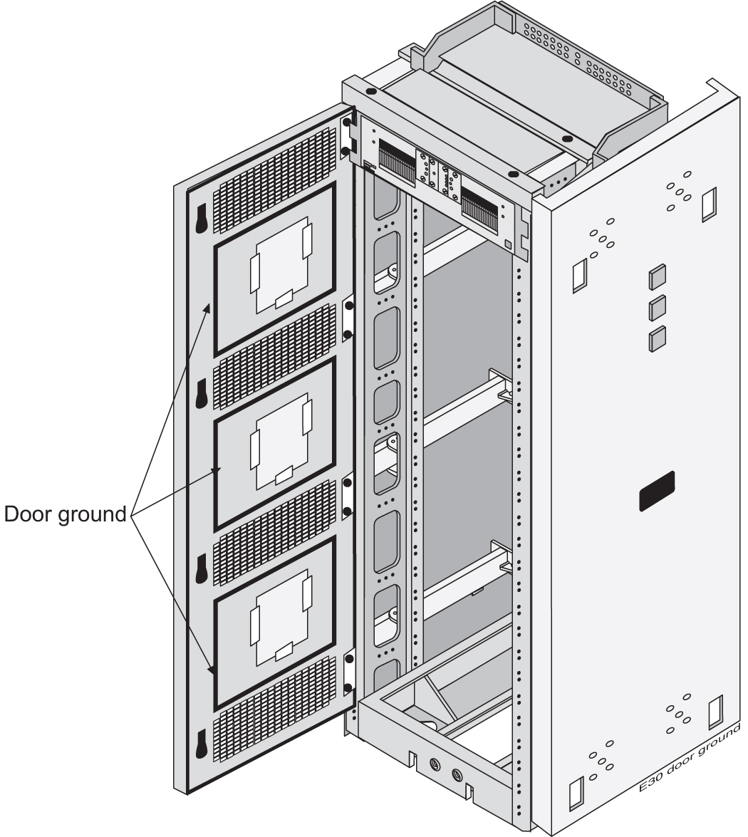
The doors installed are grounded to the frame through a double lug ground wire (see Figure 5-3) and through a screw-down latch.
Figure 5-3 Door Grounding
5.3.9 Power Requirements
Each frame requires that power be provided from two fuses/breakers at –48VDC. Additional peripherals that require alternating current (for example but not limited to, terminals, printers, and modems) must be compatible with the system and have a separate ground from the frames.
Each frame is divided into A and B power buses. In the event of loss of power on one of the buses, the other bus must be able to supply current for the entire frame. Therefore, each bus requires wiring sized to handle up to the maximum amps at –48VDC, with a maximum voltage drop of 0.5 volts. To meet this specification you must:
-
For new installations of Control and Extension Frames (as of Release 34.0) use 60 amp breakers (see note), the ELAP frames use 30 amp and 60 amp breakers, and the EPAP frames use 30 amp breakers. Local Alarms for the Frame’s Power Distribution System are provided at each frame.
Note:
Existing frames that are fused at 40 amps can be upgraded to support 60 amps with a FAP upgrade kit. 60 amps is required for frames that contain HC-MIMs. -
Use #6, two-hole, #10 Bolt, 5/8" on center lug with windows (P/N 502-0085-01) for fuse and alarm panel connectors.
Note:
If breakers are tripped by an overload, they must be switched completely OFF and then ON to reset.
5.4 Populating the System
The number of frames, shelves, and modules needed to populate the system can be determined using the following procedures.
5.4.1 Hardware Power Calculator Tool
Fans are required for all shelves that contain E5-ENET-B, E5-ATM-B, E5-E1/T1-B, E5-MCPM-B, E5-SM8G-B, HCMIM, E5-APP-B cards or SLIC. Due to higher power B cards, dual 60 Ampere power feeds to a frame may be required depending on frame configuration.
The Frame Power Budget Alarm feature (R35) provides an alarm if the power consumption of cards in a frame nears the frame-level power capacity. The current capacity value can be provisioned in the Frame Power Threshold (FPT) table or a default value of 30 Amperes can be used (30 A through 60 A are values that can be used). The feature identifies the type of cards in a frame, calculates potential current consumption based on the frame-level population of cards, compares calculated current consumption to the frame-level current capacity figure, and raises alarms based on provisioned thresholds (90%, 95%, and 98%).
A Power Calculator Tool (SS005963) can be used to analyze current power requirements and to plan power requirements for future configurations.
Table 5-1 Power Usage by Component
| Component | Power (W) | Part Number |
| E5-APP-B | 78 | 870-3096-XX |
| E5-ATM-B | 34 | 870-2972-XX |
| E5-E1T1-B | 32 | 870-2970-XX |
| E5-ENET-B | 34 | 870-2971-XX |
| E5-MASP | 58 |
7346924 870-2903-XX |
| E5-MCPM-B | 32 | 870-3089-XX |
| E5-MDAL | 12 |
7346923 870-2900-XX |
| E5-SM8G-B | 63 | 870-2990-XX |
| Fan tray | 125 | 890-0001-XX |
| HIPR2 | 18 |
7333484 870-2872-XX |
| SLIC | 34 | 7094646 |
| Telco Switch | 120 | 870-2904-01 |
5.4.2 Message Flow Control (MFC)
With Message Flow Control (MFC), an EAGLE card can inform all EAGLE cards that it has reached the allotted capacity of a particular advertised service. MFC contains the concept of system and card groups, and the groups can go into flow control independently based on the flow of messages through MFC. MFC controls all traffic across the IMT bus.
- MTP3 routing
- INM/SNM routing
Caution:
MFC can be used only with E5-based cards; however, it is required for E5-B type cards. Release 46.2 and later does not support TVG.When a card determines that the rated capacity for a service is reached, it notifies all cards that the specified service is no longer available for the remainder of the time slice and specifies the time interval that defines the remainder of the time slice. When the time slice expires the service is automatically made available again on all cards. The tasks that use MFC are INM, SNM, Linkset Reroute, SCCP, and EROUTE.
- Card Service Flow
Control Card services are provided by a card and the capacity stated by that card only affects the usage of that card. If the capacity of a card service is exhausted, only the services on that card are affected. The client card can look to another card to provide the service. A card service is used when supporting a feature with an "N+1" configuration.
- System Service Flow
Control System services are provided by the system as a whole. The capacity of the system service is rated as the capacity of the system. Several cards may provide the same system service, and it is possible that each card will have a different rated capacity. When a service request is sent to a system service, it is sent to all cards that provide the service. The capacity of the system service is limited to the rate of the lowest capacity card. If the capacity is exhausted on one card, the service for the whole system group is ‘in flow control.’ A system service is used when the available pool of resources must be limited by the weakest link (the card with the lowest rated capacity).