4 Hardware Descriptions - OEM-Based Products
4.1 OEM-Based Product Descriptions
Note:
Elements used in OEM-based products have components configured by Oracle Communications to conform to Network Equipment-Building System (NEBS) generic equipment requirements.topple:
Systems with slide shelf mounted equipment must also be anchored to the overhead cable racks. Before beginning installation, ensure the frame is properly secured to the floor and overhead cable racks to prevent the frame from tipping over when the server slide shelves are extended.4.2 OEM-Based Networking Elements
This section describes the common networking elements that can be used in OEM-based products. Networking elements of OEM-based products provide the connections and communications links for interworking between the SS7 networks, local customer networks, and the Internet.
Note:
Some OEM-based products do not use all of the networking components, for example, the MPS systems. Use Baseline Tables to determine the specific components that can be configured in system releases.Common networking components described in this section include:
4.2.1 Routers
The routers used in OEM-based products are configured by Oracle Communications for NEBS compliancy. Two types can be configured; isolation routers and dial-in routers.
Note:
Some OEM-based products do not use routers, for example, the MPS systems. Use Baseline Tables to determine the specific components that can be configured in system releases.The isolation routers provide 10/100Mbps communications between the customer LAN or dedicated network and the IP7 Front End, hubs, and host servers. Figure 4-1 shows the front view of the routers and Table 4-1 describes the LED indicator functions on the front of the router.
Figure 4-1 Front View Routers

Table 4-1 Router Front LEDs
| LED | Description |
|---|---|
|
PWR |
Indicates when power is present to the router and the power switch is in the ON position. |
|
RPS (Always OFF) |
Off when the redundant power supply is not present. On redundant power supply is present and functional. |
|
Activity |
Off-No network activity Blink-Network activity |
Figure 4-2 and Figure 4-3 show rear views of the Isolation and Dial-In routers. Link (LNK) and activity (ACT) LEDs are located near each ethernet port at the rear of the routers. Table 4-2 describes the LED indicators on the rear of the routers.
Figure 4-2 Rear View Isolation Router
Figure 4-3 Rear View Dial-in Router
Table 4-2 Router Rear LEDs
| LED | Description |
|---|---|
|
LNK |
Indicates link is established to far end connection. |
|
ACT |
Blink-indicates data activity on the link. |
4.2.2 Ethernet Switches
The following section provides an overview of the Ethernet LAN switches used in some OEM products. The ethernet switches cross-connect the components in the frames functioning as an internal Local Area Network (LAN). The switches support 24 auto-sensing 10/100Mbps ports each.
Figure 4-4 illustrates the front and rear of the Ethernet switch.
Figure 4-4 Ethernet Switch
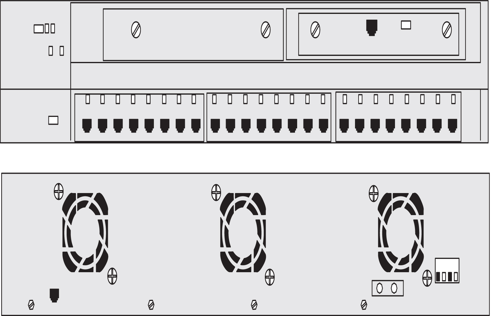
Table 4-3 describes the LEDs located on the front of the switches.
Table 4-3 Ethernet Switch LEDs
| LED | Description |
|---|---|
|
System |
Green-Indicates when power is present to the switch and the power switch is in the ON position. Amber-Indicates power is present but system is not functioning properly |
|
1 and 2 |
Indicates expansion boards WS-X2932-XL are installed and functioningLED 1 (Left board)LED 2 (Right board) |
|
RPS (Always OFF) |
Off when the redundant power supply is not present. Redudant power supply is not configured |
|
Pressing theMODE switch on the front of the WS-C2924-XL-EN changes the per-portLED indications to the following. |
|
|
STAT (port status) Default |
Off-No link. Solid green-Link present. Flashing green-Activity. Port is transmitting or receiving data. Alternating green/amber-Link fault. Error frames can affect connectivity, and errors such as excessive collisions,CRC errors, and alignment and jabber errors are monitored for a link-fault indication. Solid amber-Port is not forwarding. Port was disabled by management or an address violation or was blocked by Spanning Tree Protocol (STP). Note: After a port is reconfigured, the portLED can remain amber for up to 30 seconds asSTP checks the switch for possible loops. |
|
UTL (utilization) |
Green-The LEDs display backplane utilization on a logarithmic scuffle all port LEDs are green, the switch is using 50 percent or more of its total bandwidth capacity. If the right-mostLED is amber, the switch is using less than 50 percent of its total bandwidth. If theLED to the left of the right-mostLED is amber, the switch is using less than 25 percent of its total capacity, and so on. |
|
FDUP (port full-duplex) |
Off-Port is operating in half duplex. Green-Port is operating in full duplex. |
|
100 (port speed) |
Off-Port is operating at 10 Mbps. Green-Port is operating at 100 Mbps. |
4.3 OEM-Based Peripheral Elements
Peripheral elements used in the OEM-based products are common components required to provide service functionality. Peripheral components described in this section are:
4.3.1 Breaker Panels
The following section describes the components of the Telect Breaker Panels (BP) used in OEM-based products. The BPs provide the following features:
-
Dual-feed power inputs (Input A and Input B) to each breaker panel, totalling four breakers for the system. (30-amp domestic or 32-amp international)
-
Maximum of fourteen breakers each breaker panel
-
Breaker panels accept circuit breakers up to 20 ampere rating
-
Visual A and B input power alarms with single remote dry contact indicator
-
Replaceable alarm card
Note:
The drip tray, located under the breaker panels, is designed to assure compliance with NEBS, UL, and CE safety requirements, aiding damage control in the event of a fire. See Figure 4-5 for the location of the breaker panel drip tray.Figure 4-5 shows the details of the front view of the breaker panel
Figure 4-5 Telect Breaker Panel Front View
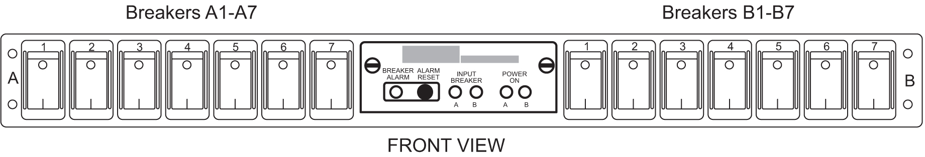
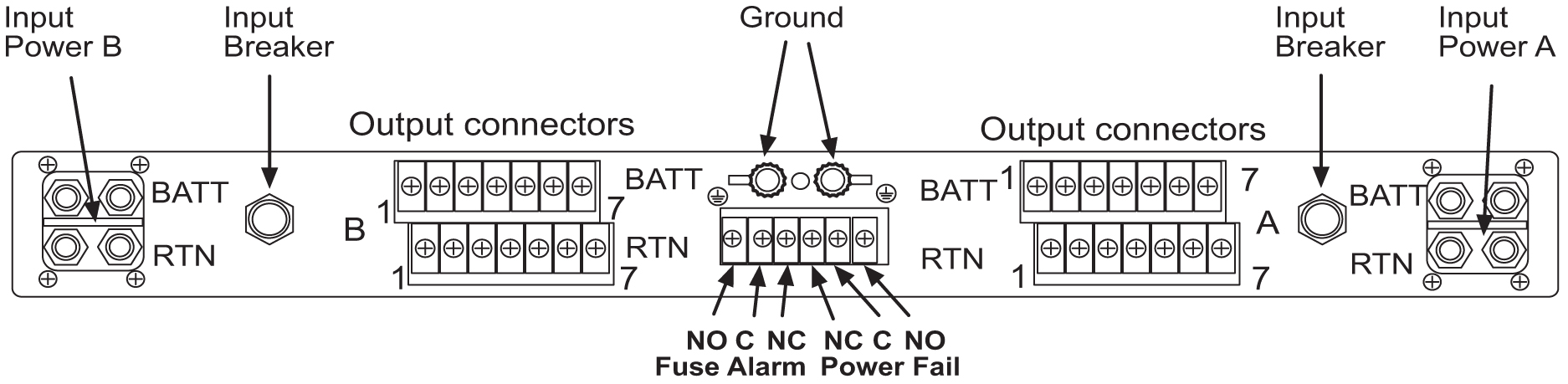
Figure 4-6 shows the rear details of the breaker panel.
Figure 4-6 Telect Breaker Panel Rear View
Note:
When breakers trip to the half-way position as a result of an overload they must be switched completely OFF then ON to reset.Figure 4-7 provides details of the alarm panel on the Telect Breaker Panel.
Figure 4-7 Telect Breaker Panel Alarms
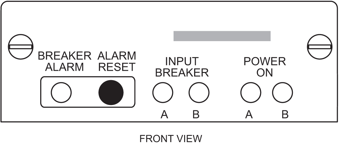
Table 4-4 lists the status LEDs on the Telect Breaker Panel.
Table 4-4 Breaker Panel LEDs
| LED | Color | Description |
|---|---|---|
|
Power On A |
Green |
Lights whenever Side A is receiving input power (LED will remain lit even if the input breaker has tripped) |
|
Power On B |
Green |
Lights whenever Side B is receiving input power (LED will remain lit even if the input breaker has tripped) |
|
Breaker Alarm |
Red |
Lights whenever an output circuit breaker has tripped or turned off |
|
Input Breaker A/B |
Green |
Lights whenever Side A/B is receiving input power (Not lit if input breaker is tripped) |
Note:
If all breakers are not turned on, the alarm LED will light. To turn off the alarm LED, press RESET and the alarm LED will reset and turn off.