3 Hardware Descriptions - EAGLE
3.1 Introduction
This chapter provides detailed descriptions of the various hardware associated with the EAGLE including MPS systems. This chapter is designed to aid personnel in configuration, planning, and replacing components in the systems.
This chapter contains detailed descriptions of the frames, shelves, modules, and power distribution in the systems.
3.2 EAGLE
EAGLE is a large-capacity, multi-functional, fully scalable Signaling Transfer Point (STP). The EAGLE is NEBS-compliant (GR-63-CORE, Network Equipment-Building Systems). High capacity and scalability allow the EAGLE to grow from a single-shelf, 80-link STP to a multi-frame, 2800-link STP.
Due to the distributed processor design, EAGLE does not have a separate central processing unit to bottleneck traffic throughput. Application and interface cards are designed to provide plug and play type functionality that facilitates future growth. EAGLE application and interface cards generally do not have specific shelf or frame limitations, allowing you to fully customize and define how your STP is configured. EAGLE also supports a variety of interface cards to support connectivity to a wide range of network elements. EAGLE provides connectivity interfaces for IP, ATM, T1, and E1 protocols.
IP Connectivity
The EAGLE provides connectivity between SS7 and IP networks. It receives and sends switched circuit network (SCN) native signaling at the edge of the IP network. The signaling gateway function may relay, translate, or terminate SS7 signaling in an SS7-Internet gateway. The signaling gateway function may also be co-resident with the media gateway function to process SCN signaling associated with line or trunk terminations controlled by the media gateway.
Monitoring
In EAGLE STP, Signaling Transport Cards (STC) monitor the activity of Link Interface Modules (LIM) and transfer information to an Integrated Data Acquisition system such as the Extended Services Platform (ESP) subassembly.
Note:
STC cards are based on E5-ENET B cards (P/N 870-2971-xx) or SLIC cards (P/N 7094646), and can be configured in any slot (except slots reserved for HIPR2 cards).3.3 Multi-Purpose Server (MPS)
Oracle Communications' Multi-purpose Server (MPS) is a hardware and software platform that can be configured to support ELAP or EPAP.
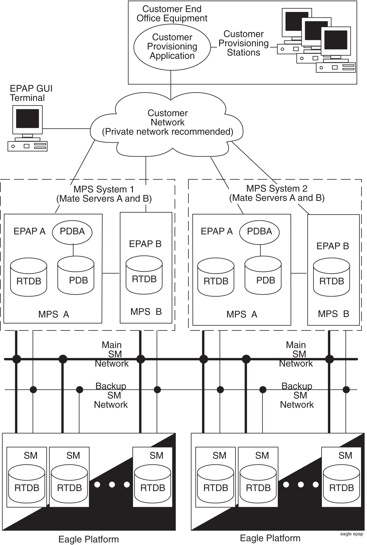
Figure 3-1 shows an overview of how the EPAP MPS is used with the EAGLE.
The MPS provides an interface between the customer provisioning network and the EAGLE SM cards. As the customer’s data is updated, the MPS stores the data and updates the SM cards. An MPS is usually co-located with an EAGLE.
Figure 3-1 EPAP MPS Overview
Layered Design
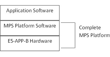
MPS is based on the E5-APP-B card and uses a layered design (see Figure 3-2) with defined interfaces to enable application and platform changes to be made independently. This design provides an environment in which changes made to platform components need not cause changes in application.
Figure 3-2 Layered Design for MPS and Applications
Hardware Components
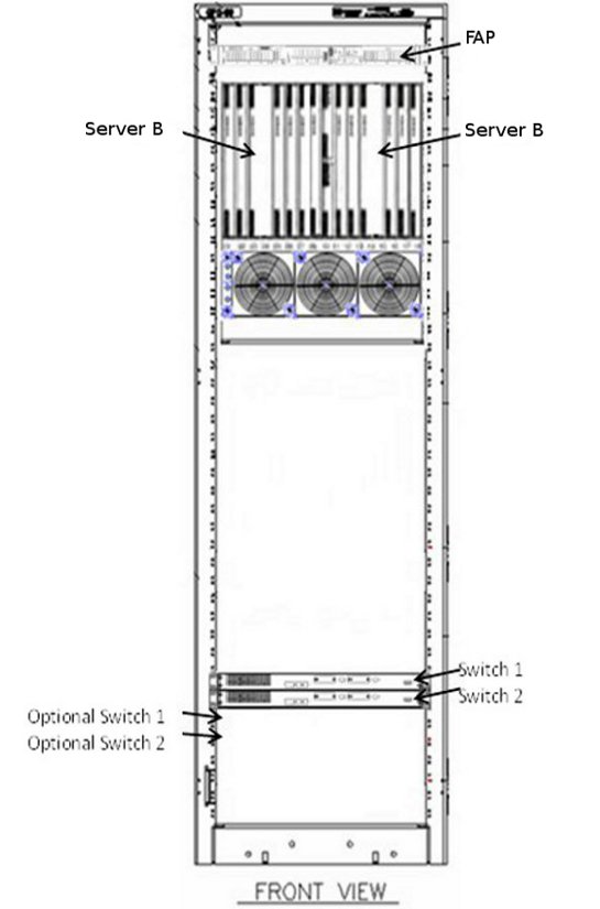
This section includes a description of MPS hardware components and an overview of the disks and file systems. Figure 3-3 illustrates the following equipment.
-
One EAGLE FAP
-
One Fan tray
-
Two to four Switches
-
Two MPS Servers
-
One General Purpose Frame
Figure 3-3 MPS Hardware Overview
Note:
If the Dual ExAP Configuration feature is used, the MPS Frame would instead contain four to six switches and four MPS server.
DANGER:
DO NOT install AC powered equipment in the MPS frame. No commercially powered AC equipment should be used or placed within 7 feet of -48VDC equipment. Doing so can create a shock hazard to personnel and equipment.
3.4 EAGLE Card Overview
The EAGLE Card Overview table is a resource table that provides an overview of information for cards that can be provisioned in EAGLE. For a detailed description of supported hardware, see Table below.
This table lists the following card information:
- GPLs and applications that can run on the card
- Provisioned card type
- Name of the card as shown on the card label
- Card part number
- Number of shelf slots that the card occupies (1 or 2)
- Number of physical ports on the card
- Maximum number of links that can be assigned to the card
Table 3-1 EAGLE Card Overview Table
| Card Applications | Card GPLs | Provisioned Card Type | Card Name as shown on the card label | Card Part Number | Slots per Card | Ports per Card | Links per Card |
|---|---|---|---|---|---|---|---|
| atmansi | atmhc69 bldc32 | limatm | E5-ATM-B | 870-2972-01 | 1 | 4 (3 used) | 2 |
| atmitu | lime1atm | ||||||
| ccs7itu | ss7hc69 bldc32 | lime1 | E5-E1T1-B | 870-2970-01 | 1 | 8 | 64 |
| ss7hc69 blsl932 | SLIC | 7094646 7352578 | 1 | 4 | 96 | ||
| ccs7itu | ss7hc69 bldc32 | lime1 (for SE-HSL) | E5-E1T1-B | 870-2970-01 | 1 | 8 | 2 |
| ss7hc69 blsl932 | SLIC | 7094646 7352578 | 1 | 2 | 3 | ||
| enumhc | enum64 bldc64 | dsm | E5-SM8G-B | 870-2990-01 | 2 | 2 Ethernet | 1 Ethernet for MPS link |
| 1 Ethernet for Signaling (16 TCP; 1 UDP) | |||||||
| enum64 blslc64 | SLIC | 7094646 7352578 | 1 | 4 Ethernet | 2 Ethernet for MPS links | ||
| 2 Ethernet for Signaling links (2 UDP) | |||||||
| eroute | erthc69 bldc32 | stc | E5-ENET-B | 870-2971-01 | 1 | 2 | 2 Ethernet |
| erthc69 blsl932 | SLIC | 7094646 7352578 | |||||
| hipr2 | hipr2 | N/A | HIPR2 | 7333484 | 1 | N/A | N/A |
| 870-2872-01Foot 2 | |||||||
| 870-2872-02Foot 2 | |||||||
| ips | ipshc69 bldc32 | ipsm | E5-ENET-B | 870-2971-01 | 1 | 2 (use only A) | 1 ipshc service |
| ipshc69 blsl932 | SLIC | 7094646 7352578 | 1 | 1 | 1 Ethernet | ||
| ipsg | ipsg69 bldc32 | enet enetb | E5-ENET-B | 870-2971-01 | 1 | 4 | 32 |
| ipsg69 blsl932 | enetb | SLIC | 7094646 7352578 | 1 | 4 Ethernet | 2 Ethernet for Signaling links (32 SCTP) 2 Ethernet for Fast Copy | |
| ipsg69 blsl932 | slic | SLIC | 7094646 7352578 | 1 | 4 Ethernet | 2 Ethernet for Signaling links (128 SCTP) 2 Ethernet for Fast Copy | |
| ipsg + GTT | ipsg932 blsl932 | slic | SLIC | 7094646 7352578 | 1 | 4 Ethernet | 2 Ethernet for Signaling links (32 SCTP) 2 Ethernet for Fast Copy |
| mcp | mcphc69 bldc32 | mcpm | E5-MCPM-B | 870-3089-01 | 1 | 2 (use only A) | 1 Ethernet |
| mcphc69 blsl932 | SLIC | 7094646 7352578 | 1 | 1 | 1 Ethernet | ||
| oam | oamhc69 bldc32 | N/A | E5-MASP | 7346924 | 2 | 2 | N/A |
| 870-2903-01Foot 2 | |||||||
| 870-2903-02Foot 2 | |||||||
| 870-2903-03Foot 2 | |||||||
| sfapp | sfapp blslc64 | slic | SLIC | 7094646 7352578 | 1 | 1 Ethernet | 1 Ethernet for Visualization links (8 TCP) |
| siphc | sip64 bldc64 | dsm | E5-SM8G-B | 870-2990-01 | 2 | 2 Ethernet | 1 Ethernet for MPS link |
| 1 Ethernet for Signaling (16 TCP; 1 UDP) | |||||||
| sip64 blslc64 | SLIC | 7094646 7352578 | 1 | 4 Ethernet | 2 Ethernet for MPS links | ||
| 2 Ethernet for Signaling links (16 TCP; 2 UDP) | |||||||
| ss7ansi | ss7hc69 bldc32 | limt1 | E5-E1T1-B | 870-2970-01 | 1 | 8 | 64 |
| ss7hc69 blsl932 | SLIC | 7094646 7352578 | 1 | 4 | 96 | ||
| ss7ansi | ss7hc69 bldc32 | limt1 (for ST-HSL-A) | E5-E1T1-B | 870-2970-01 | 1 | 8 | 2 |
| ss7hc69 blsl932 | SLIC | 7094646 7352578 | 1 | 2 | 3 | ||
| vsccp | sccp64 bldc64 | dsm | E5-SM8G-B | 870-2990-01 | 2 | 2 Ethernet | 2 Ethernet for MPS links |
| sccp64 blslc64 | SLIC | 7094646 7352578 | 1 | 3 Ethernet | 2 Ethernet for MPS links 1 Ethernet for Visualization links (8 TCP) | ||
| slic | 7094646 7352578 | 1 | 3 Ethernet | 2 Ethernet for MPS links 1 Ethernet for Visualization links (8 TCP) | |||
| N/A | N/A | N/A | E5-MDAL | 7346923 | 2 | N/A | N/A |
| 870-2900-01Foot 2 | |||||||
| elap | N/A | e5appb | E5-APP-B | 870-3096-xx | 2 | 4 | N/A |
| epap | |||||||
| lsms | |||||||
| nas | |||||||
| imf |
3.5 Hardware Baselines
Hardware Baselines contains a complete listing of the hardware available for each software release. The appendix lists configurable modules arranged in alphabetical order indexed to system software releases. For example, all hardware available will have a bold X where the hardware module row crosses the release column.
3.6 Frames
The system uses standard 7-foot high, 23-inch wide frames (inside dimension). These floor mounted frames are constructed from channel steel and painted with electrostatic powder. Depending on the configuration, the system uses two frames to accommodate a maximum of 2800 SS7 signaling links.
Note:
A heavy-duty frame with the capability to support the greater weight of COTS equipment is shipped with all new systems. The generic frame is no longer being shipped but is supported in the documentation.Note:
With the large system feature, depending on configuration, the system can accommodate up to 2800 links. The large system feature applies to the EAGLE systems only.The system can use two types of frames:
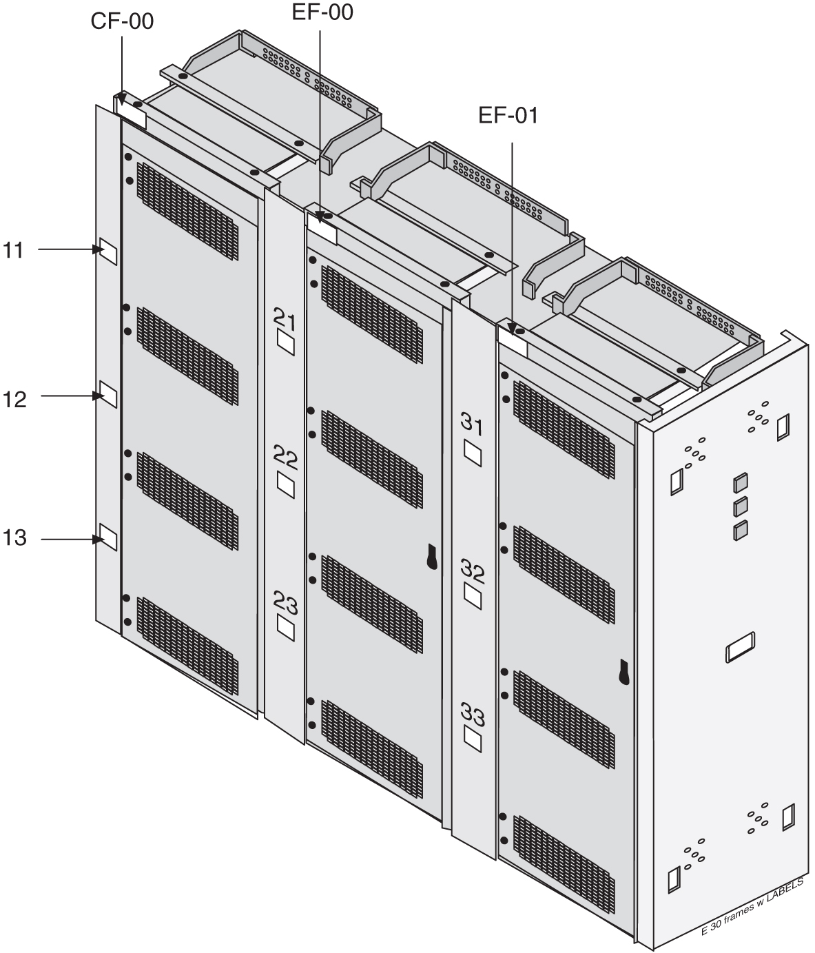
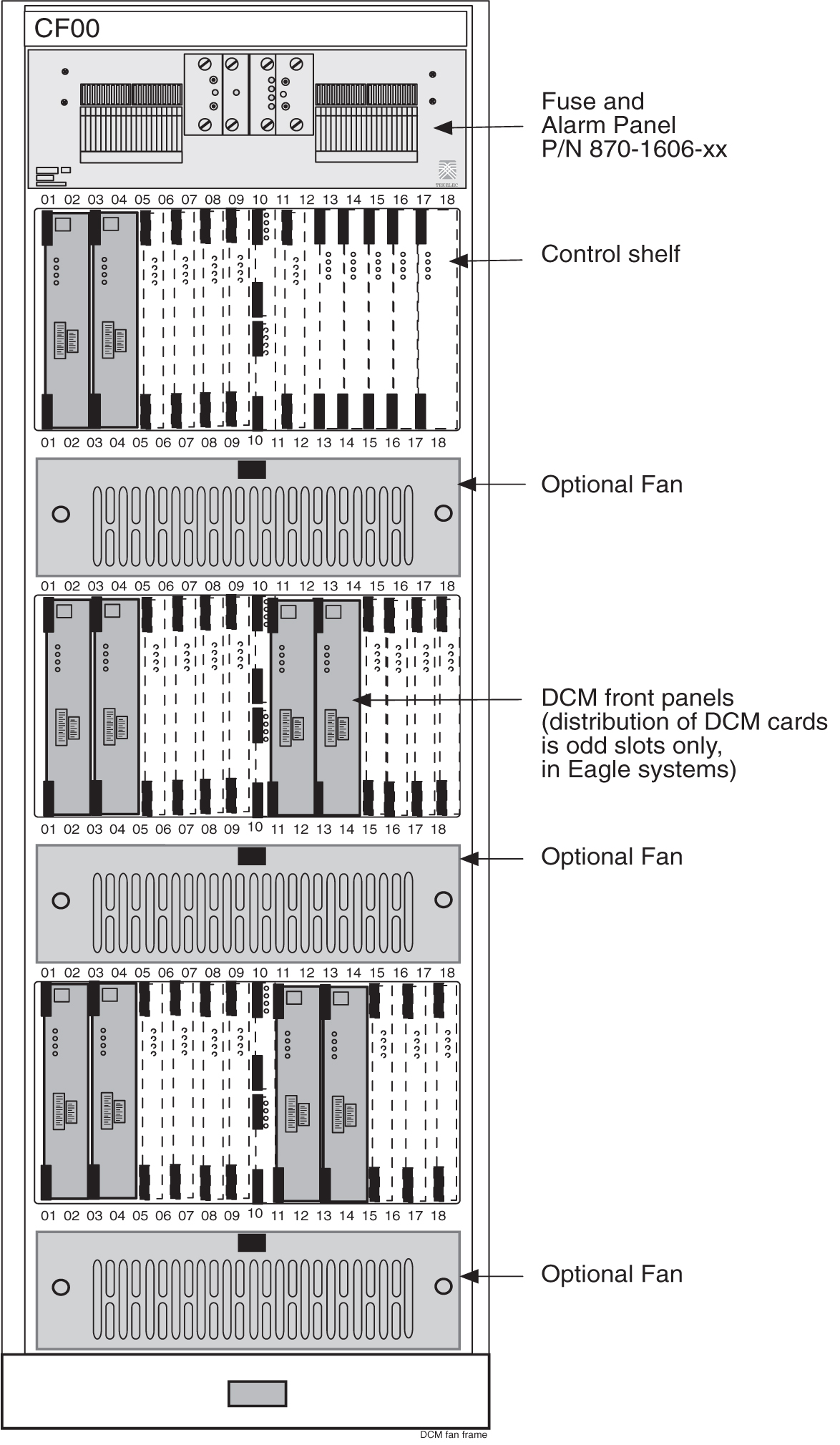
Figure 3-4 shows a system with a Control Frame (CF-00) and two Extension Frames (EF-00 and EF-01).
Figure 3-4 Frames
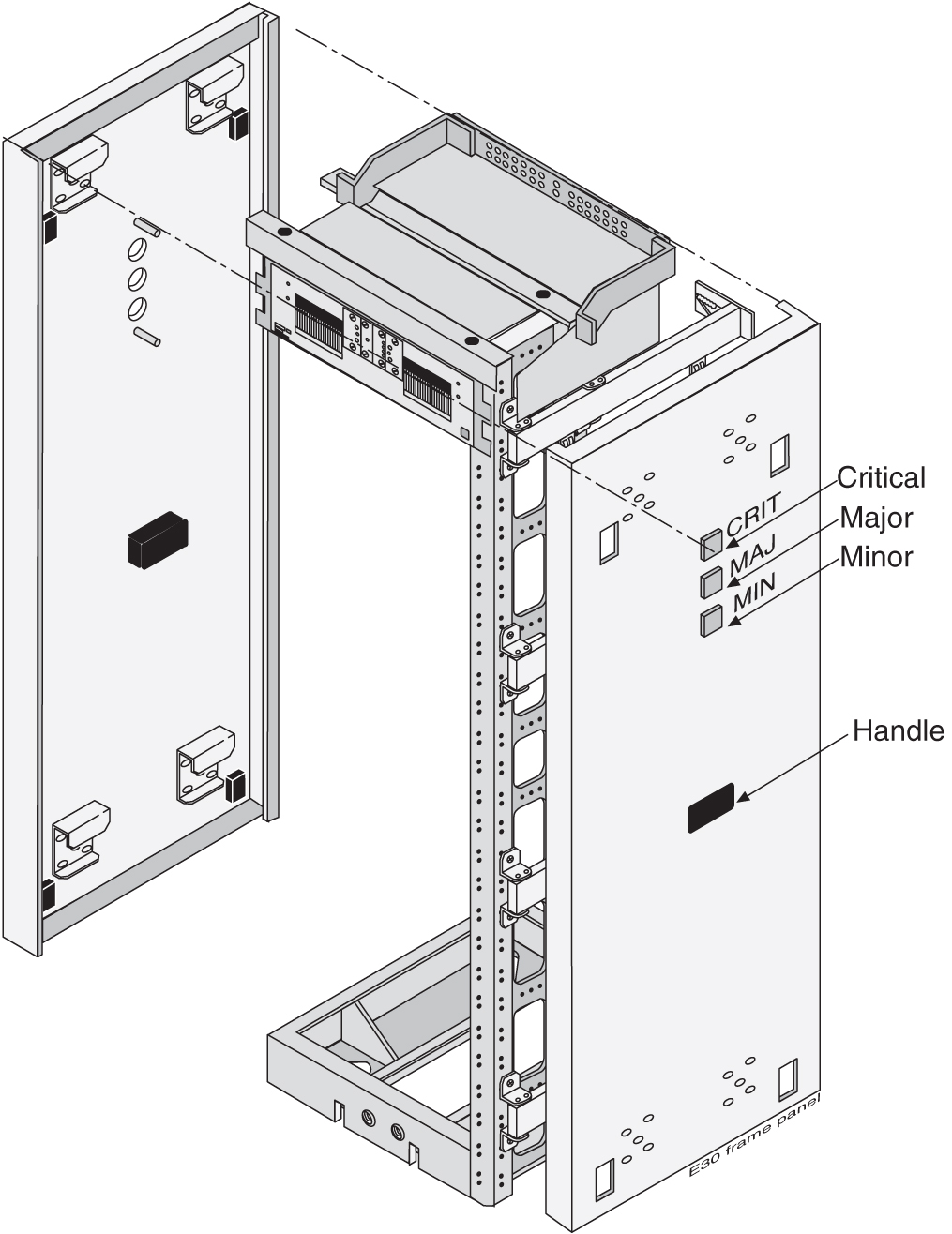
Lamp indicators (P/N 525-0067-R01) can be mounted on either side of the row of frames on the end panels (as shown in Figure 3-5), which show three levels of alarm conditions:
Figure 3-5 Frame End Panel with Lamp Indicators
The doors on the front of each frame provide electromagnetic interference shielding and lock in place with a screw lock. Mounted on the inside of the doors are card locators, used to record the location of each card in a shelf and important data regarding the application that each card provides. The shelf backplanes are protected at the rear of the frame by removable transparent Plexiglas panels.
The following lists the part numbers for the panels for the frames:
-
P/N 840-0064-01 End row panel, full depth, standard frame, NTW.
-
P/N 870-2278-02 Full depth alarm side panel, heavy-duty frame, NTW.
A Fuse and Alarm Panel (FAP), located at the top of each frame, distributes –48VDC to all the shelves in the frame. Fuses are located on the front of the fuse and alarm panel. For more information on the fuse and alarm panel (refer to Fuse and Alarm Panels).
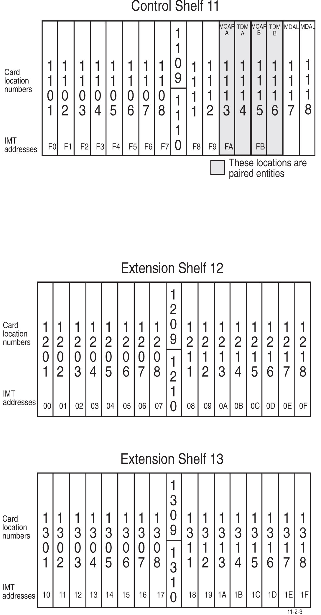
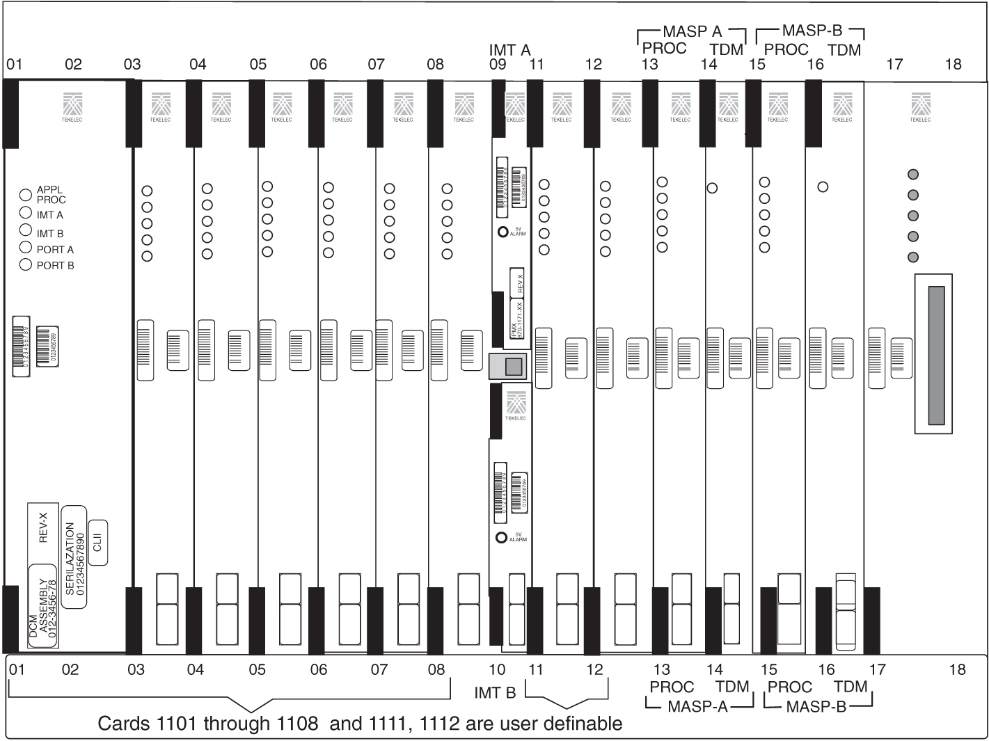
The numbering of the shelves, with the shelf identification backplane wiring, circuit card location, and with the Inter-processor Message Transport (IMT) address in small print at the bottom of the faceplates is shown in Figure 3-6. The HIPR2 card provides Inter-processor Message Transport (IMT) bus continuity for all cards connected to the IMT bus.
Figure 3-6 Control Frame CF-00 Numbering Plan
3.6.1 Extension Frame
The Extension Frame (EF) accommodates up to three extension shelves, each shelf is capable of supporting up to 16 Link Interface Modules (LIMs), E5 Interface Modules, E5-TSM Modules, E5-STC Modules or E5-MCPM-B Modules in any combination. E5-SM (E5-SMxG/E5-SMxG-B) cards must be inserted into odd numbered slots in eagle systems.
The system can have up to five Extension Frames, EF-00 to EF-04. EF-04 supports only one extension shelf. The numbering of the shelves is shown, with the shelf identification backplane wiring, circuit card location, and the Inter-processor Message Transport (IMT) address in small print at the bottom of the faceplate. The numbering of the card locations on the extension frames and the IMT address is shown in the following figures.
Figure 3-7 Extension Frame EF-00 Numbering Plan
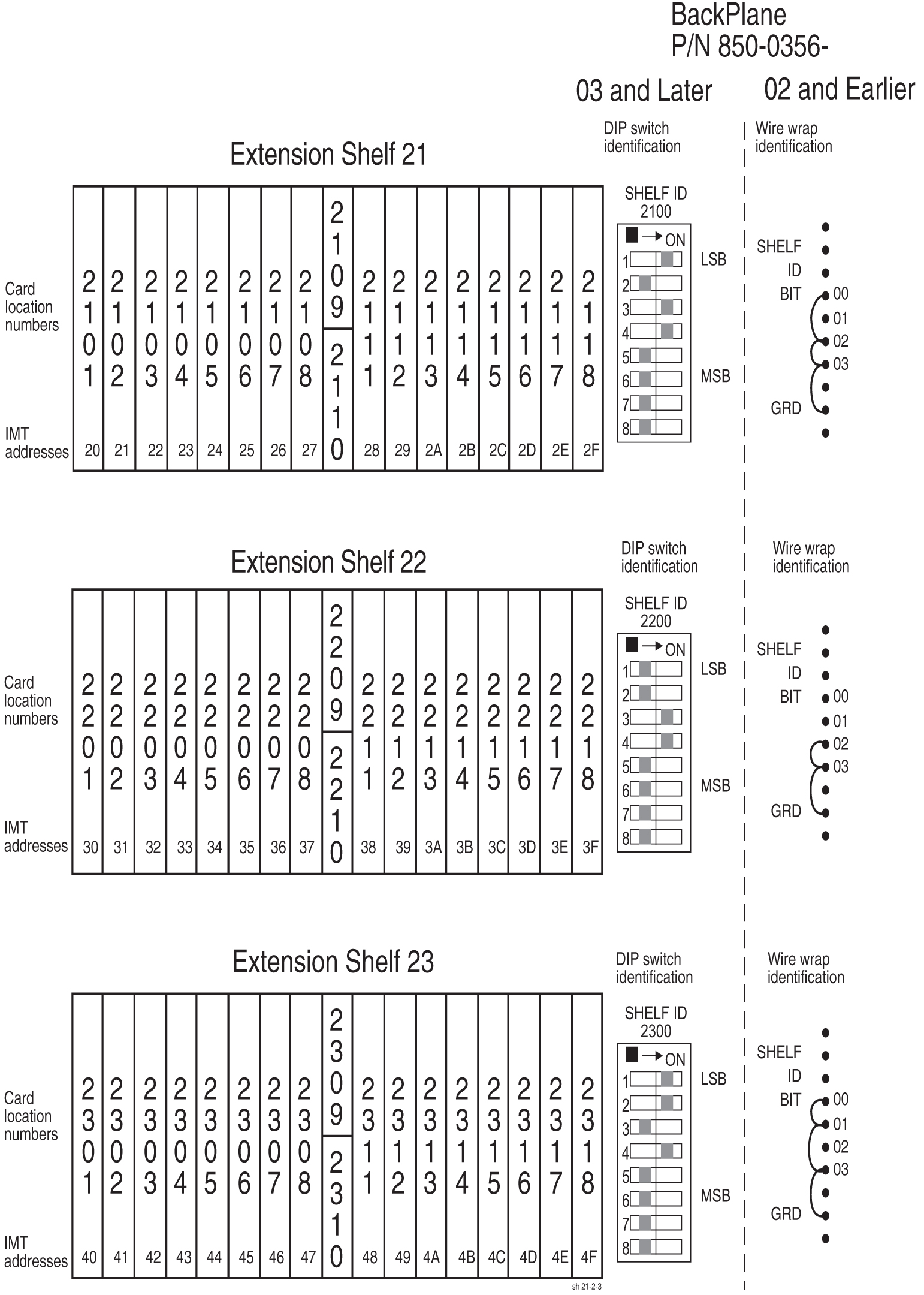
Figure 3-8 Extension Frame EF-01 Numbering Plan
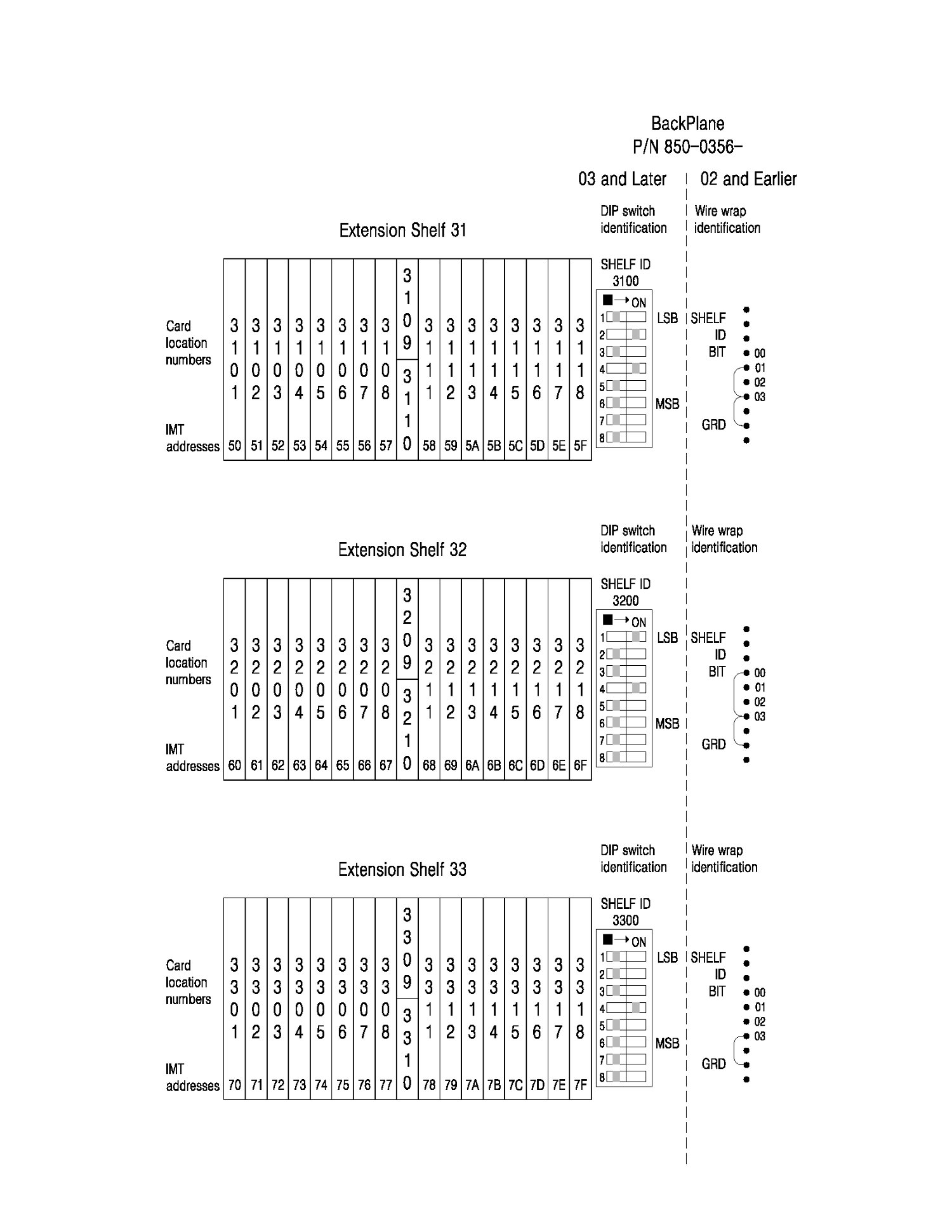
Figure 3-9 Extension Frame EF-02 Numbering Plan
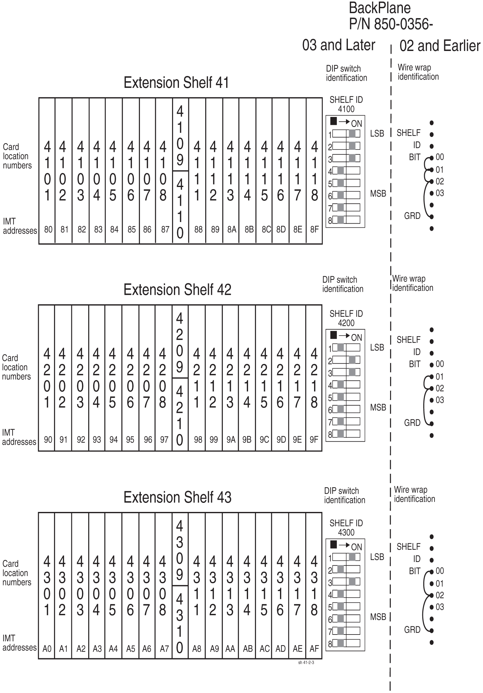
Figure 3-10 Extension Frame EF-03 Numbering Plan
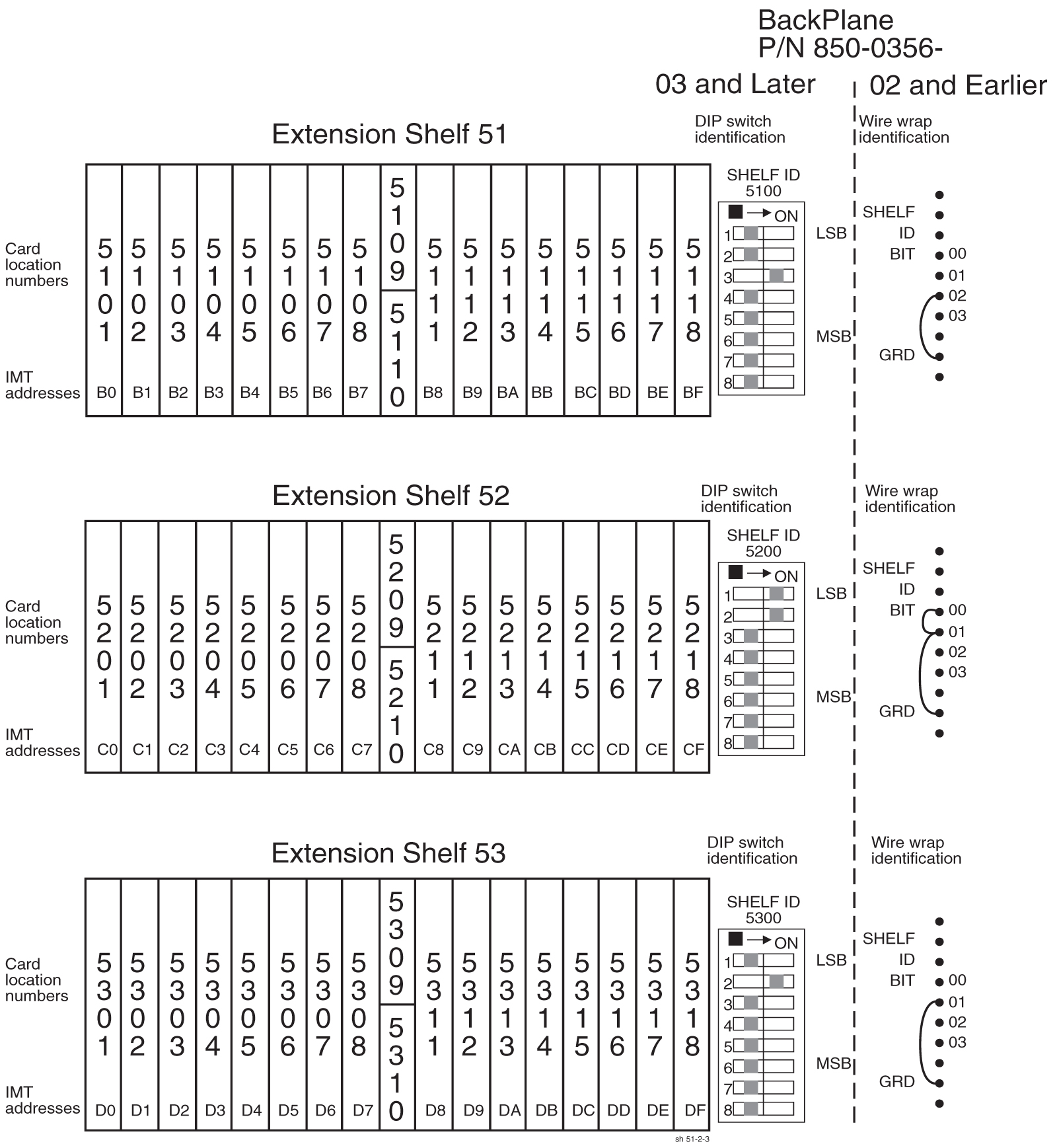
Note:
6200 and 6300 shelf can be used for Telco switch and E5-APP-B cards.Figure 3-11 Extension Frame EF-04 Numbering Plan
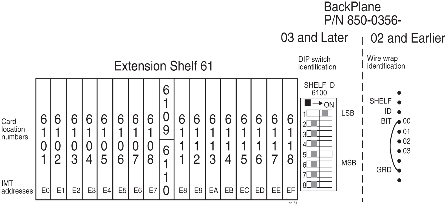
Figure 3-12 Extension Shelf Backplane ID (P/N 850-0356-03)
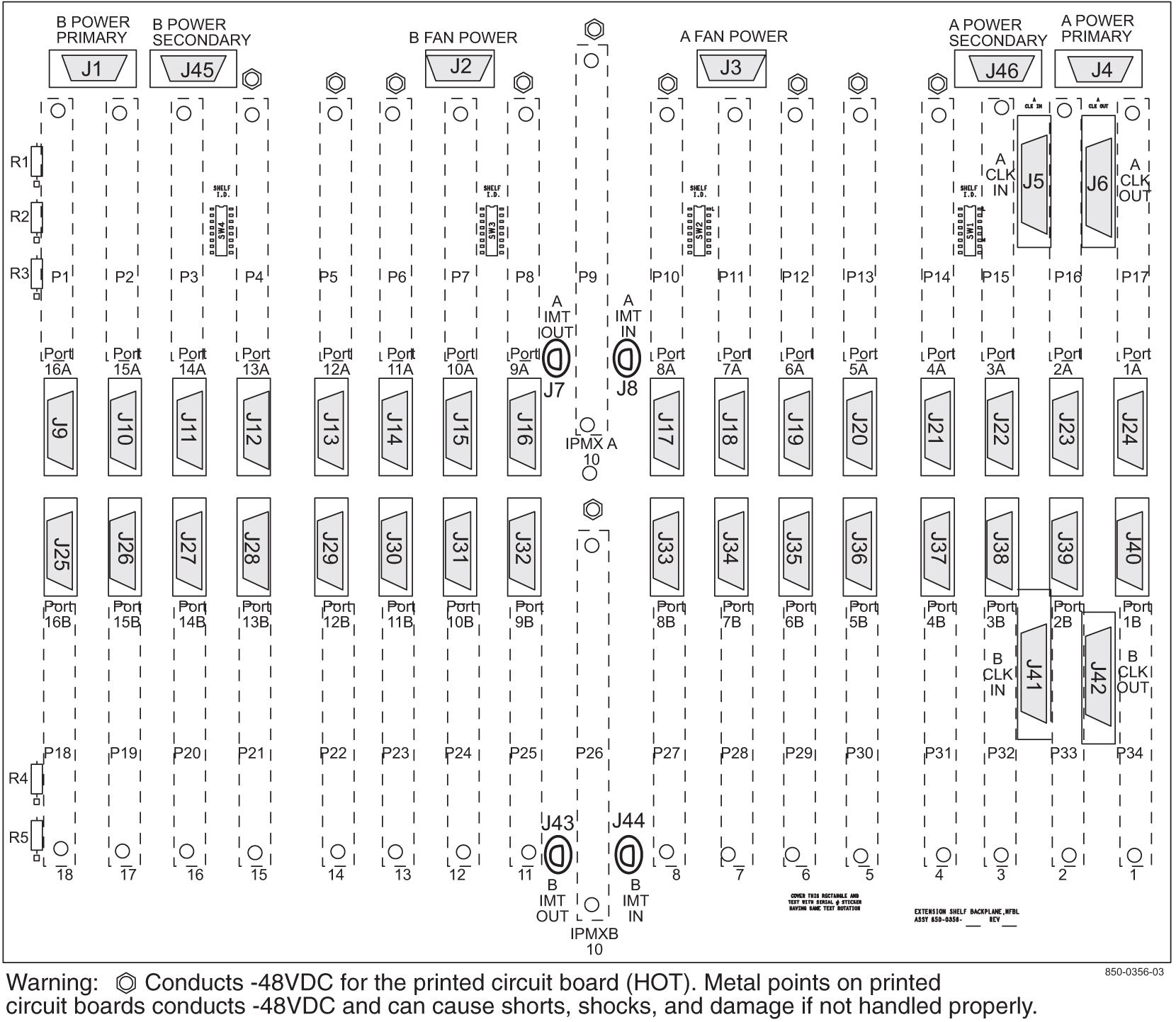
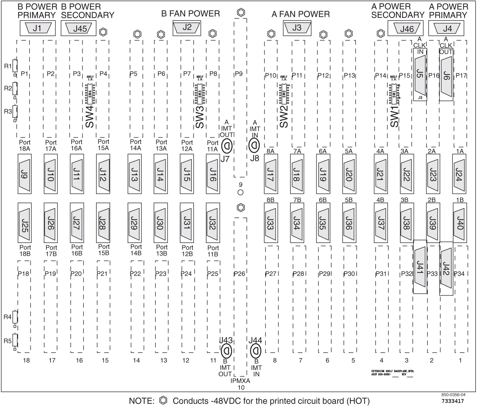
Figure 3-13 Extension Shelf Backplane ID (P/N 850-0356-04/06/7333417)
3.6.2 Miscellaneous Frame
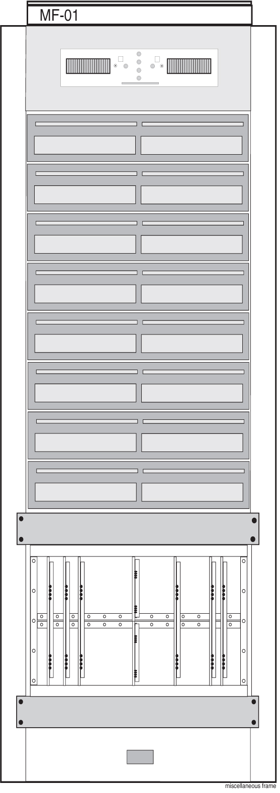
The Miscellaneous Frame (MF) is an optional frame that can be used to mount holdover clocks, test equipment, jack panels, spare cards, and other customer-specified accessories or equipment. The optional spare card storage shelf is equipped with card guides and doors for safe storage of all system cards.
The Miscellaneous Frame (MF) is equipped with a Fuse and Alarm Panel (FAP) that can provide fused –48VDC to equipment mounted in the frame.
An example of a miscellaneous frame is shown in Figure 3-14.
Figure 3-14 Miscellaneous Frame
3.6.3 Control Frame
The Control Frame (CF) is the principle frame for the system. The top shelf is the control shelf, containing all the components of the Maintenance and Administration Subsystem (MAS), and up to ten additional Link Interface Modules (LIMs), E5 Interface Modules, E5-TSM Modules, E5-STC Modules or E5-MCPM-B Modules in any combination. E5-SM (E5-SMxG/E5-SMxG-B) Modules (E5-SM modules require two card slots).
The control frame can also contain up to two extension shelves. Each extension shelf can accommodate up to 16:
- Link Interface Modules (LIMs), E5 Interface Modules, E5-TSM Modules, E5-STC Modules or E5-MCPM-B
Or each extension shelf can accommodate up to eight:
- E5-SM (E5-SMxG/E5-SMxG-B) Modules (E5-SM (E5-SMxG/E5-SMxG-B) Modules (E5-SM modules require two card slots).
All cards can be inserted in any slot except for those locations dedicated to the HIPR2 and MASP cards. In EAGLE systems and IP7 4.0 and earlier systems, E5-SM (E5-SMxG/E5-SMxG-B) modules must be placed into odd-numbered slots, and due to their width the adjoining even-numbered slot will be taken as well.
3.6.4 Control Shelf
The control shelf is divided into two parts. One part is used by the Maintenance and Administration Subsystem (MAS) and contains the following hardware:
- Two E5-based Maintenance and Administration Subsystem Processors (E5-MASP) cards.
- One E5-based Maintenance Disk and Alarm (E5-MDAL) card
Two HIPR2 cards provide Inter-processor Message Transport (IMT) bus continuity for all cards connected to the IMT bus.
Note:
HIPR2 cards are installed at the factory or by Technical Support and are not installed by customers.The remainder of the control shelf can be occupied by up to ten of the following cards, in any combination and in any location not dedicated to an MASP pair or HIPR2 card:
- Link Interface Module (LIM)
- E5 Interface Modules
- E5-TSM Modules
- E5-STC Modules
- E5-IPSM Modules
- E5-MCPM-B Modules
E5-SM (E5-SMxG/E5-SMxG-B) cards must be inserted into odd numbered slots in EAGLE systems.
Caution:
After the frame has been shipped or moved, prior to applying power, remove all cards. Reset all cards carefully to avoid possible faulty connections. All cards are hot swappable.The control shelf, shown in Figure 3-15, consists of top and bottom assemblies with die-formed channel slots to accept the top and bottom edges of the cards. The assemblies are anchored to the sheet steel side panels which are equipped with integral flanges for attaching the shelf to a 23-inch rack. The shelf backplane consists of an epoxy-glass printed circuit board and associated connectors. The section Control Shelf Backplanes describes the control shelf backplane.
The control frame can also contain up to two extension shelves. Each extension shelf can accommodate up to 16 Link Interface Modules (LIMs) or E5 Interface Modules, E5-TSM Modules, E5-STC Modules or E5-MCPM-B Modules in any combination; except for those locations dedicated to the HIPR2 and MAS cards. All cards can be inserted in any card location.
E5-SM (E5-SMxG/E5-SMxG-B) cards are only configured in available odd numbered slots, and require two card slots.
Figure 3-15 Control Shelf Front with Card
3.6.5 Control Shelf Backplanes
This section describes the control shelf backplanes (P/N 850-0330-03/04/06/07 and 7333412), all can be used in EAGLE systems.
Note:
Control Shelf Backplane can be used with the HIPR2 in the EAGLE system with minor modifications and the addition of adapter cable (P/N 830-1185-01). See "Hardware Baseline Table" in Release Notes for compatible control shelf and extension backplane part numbers. The adapter cable is not necessary for customers not wanting high speed links.Note:
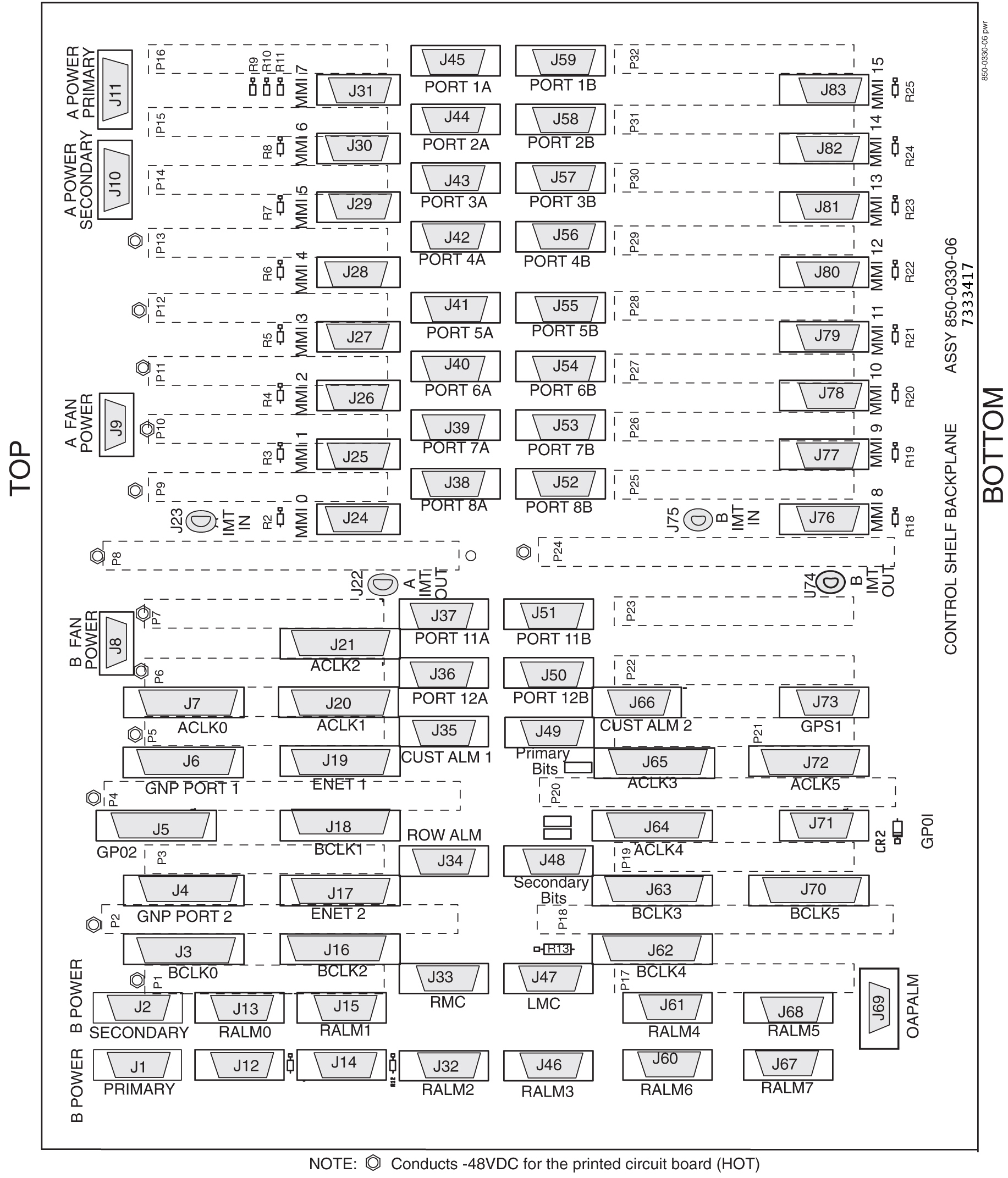
The clocking and fan control signals used to support extension frames 6 and 7 are eliminated in the 850-0330-06 version and later of the Control Shelf Backplane because those frames are no longer supported in the EAGLE system.The control shelf backplane provides connectors for the system circuit cards. These connectors are four column High Density Interconnect (HDI) male headers with shrouds of varying pin quantities, depending on card position.
- LIM, E5-ENET, and E5-E1T1 cards can be used in slots 1, 2, 3, 4, 5, 6, 7, 8, 11, and 12.
- HIPR2 cards are connected in slots 9 and 10.
Note:
HIPR2 cards are installed at the factory or by Technical Support and are not installed by customers. - The HCMIM and E5-SM4G cards, used in EAGLE systems, are mounted only in available odd numbered slots 1, 3, 5, 7, and 11.
Note:
The E5-SM4G may also be mounted in available odd numbered slots 1, 3, 5, 7, 11, 13, 15, and 17 in the extension shelf.
Note:
Throughout this document, the term E5-SM4G refers to both the E5-SM4G (P/N 870-2860-xx) and the E5-SM8G-B (P/N 870-2990-xx) cards unless specifically noted otherwise.The control shelf backplane provides –48VDC power and ground to all card positions. The power is distributed into two parts, A and B. Power is brought to the shelf from the Fuse and Alarm Panel (FAP) using two cables. The connectors on the control shelf backplane are DB-26 high density connectors. The power is distributed over two separate pins per power connection to handle the current load. The current capacity of the connector pins is 1.5A per pin for a total of 3A per pair. Installation Guide tables list the shelf location, card type, and fuse location in the fuse and alarm panel for the control shelf backplane.
Note:
Cards that are provisioned in redundant pairs must be on separate power buses. This provides backup processing capabilities with the loss of either the A or B power buses. All MASP and HIPR2 cards are provisioned in pairs and are redundantly powered from separate power buses.The control shelf power connectors are designated as:
- J1 (B Power) and J4 (A Power) on control shelf backplane (P/N 850-0330-04)
- J1 (B Power Primary) and J2 (B Power secondary) J11 (A Power primary) and J10 (A Power Secondary) on control shelf backplane (P/N 850-0330-06/07 and 7333412).
Caution:
Disconnect both Input and supply sources when repairs require removal of power. This will take the system down.Note:
Control Shelf Backplane (P/N 850-0330-03/04) can be used with the HIPR2 in the EAGLE system with minor modifications and the addition of adapter cable (P/N 830-1185-01).The following figures depict the rear connector view of control shelf backplane (P/N 850-0330-03/04/06/07 or 7333412).
Figure 3-16 Control Shelf Backplane (P/N 850-0330-03/04)
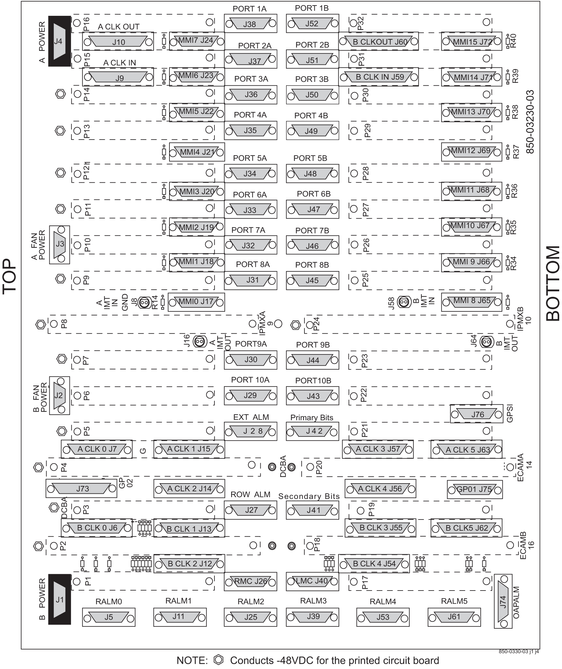
Figure 3-17 Control Shelf Backplane (P/N 850-0330-06/07 or 7333412)
3.6.6 Extension Shelf
The extension shelf provides the mounting space for up to 16 Link Interface Modules (LIMs), E5 Interface Modules, E5-TSM Modules, E5-STC Modules or E5-MCPM-B Modules and E5-SM (E5-SMxG/E5-SMxG-B) cards (mounted in odd numbered slots, requiring two slots).
Note:
HIPR2 and HIPR cards are installed at the factory or by Technical Support and are not installed by customers.Figure 3-18 Extension Shelf with LIMs
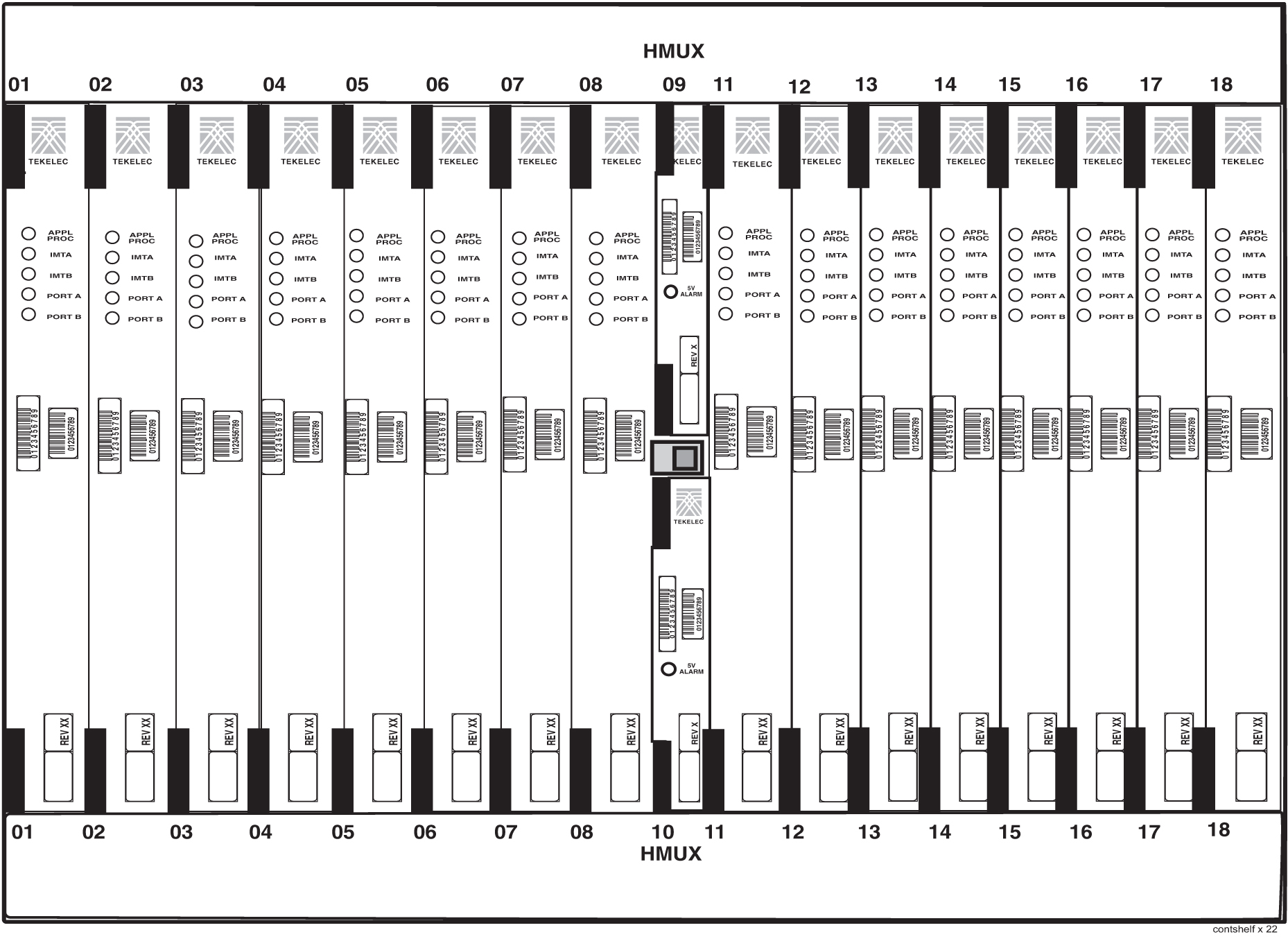
Figure 3-19 Shelves with DCM and LIM Cards in Control Frame
The extension shelf consists of die-formed top and bottom assemblies with die-formed channel slots to accept the top and bottom edges of the cards. The assemblies are anchored to the side panels which are equipped with integral flanges for attaching the shelf to a 23-inch rack in a 26-inch frame. The shelf backplane consists of an epoxy-glass printed circuit board and associated connectors.
The extension shelf backplane is shown in the figure for the Extension Shelf Backplanes. Each card is equipped with a power converter that takes the –48VDC input from the backplane and converts it to +5VDC and/or +3VDC.
3.6.7 Extension Shelf Backplanes
This section discusses the technical aspects of the extension shelf backplanes (P/N 850-0356-03/04/06 and 7333417) and the extension shelf backplanes (P/N 850-0356-01/02) used in the system.
The extension shelf backplane provides connectors for 18 circuit cards. These connectors are four column High Density Interconnect (HDI) male headers with shrouds of varying pin quantities depending on card position. The reverse or component side of the backplane contains DB style connectors for interfacing to the rest of the system. The extension shelf backplane provides shielding on all of the interface connectors to prevent Radio Frequency Interference (RFI).
Power Distribution
Caution:
This is a redundant system to allow service during normal maintenance. When repairs require a total power disconnect both input supply sources must be disconnected. This will cause service interruption and take down the system.The extension shelf backplane provides –48VDC power and return to all card positions. The power is divided into parts A and B and brought to the shelf from the Fuse and Alarm Panel (FAP) using two cables (P/N 830-0315-xx). The power connectors on the extension shelf backplane are DB-26 high density connectors with two pins per power connection to handle the current load. The current capacity of the connector pins is 1.5A per pin for a total of 3A per pair. The extension shelf primary power connectors are designated as J4 and J1, and the secondary power connection are on backplane (P/N 850-0356-03/04/06 and 7333417) are J45 and J46 secondary.
In Installation Guide, tables list the shelf location, card type, and fuse location in the fuse and alarm panel for the extension shelf backplane.
Note:
Cards that are provisioned in redundant pairs must be on separate power buses. This provides backup processing capabilities with the loss of either A or B buses.Interface Connectors
Behind each slot on the extension shelf backplane are two DB-26 connectors. These provide connection to the outside world in the form of TCP/IP networks, SS7 links, or X.25 networks. The interface connectors are designated as J9 through J40.
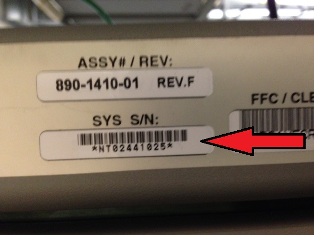
3.6.8 Locating the EAGLE System Number
The Oracle Communications EAGLE System number is printed on a label affixed to the outside of an EAGLE frame. The number begins with either an NT or TA number.
The following figures provide examples of the label placement:
Figure 3-20 EAGLE System Number Frame View
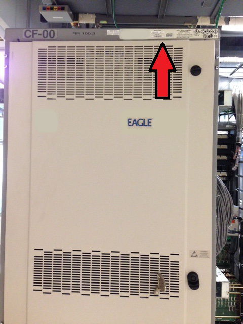
Figure 3-21 EAGLE System Number Medium View
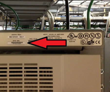
Figure 3-22 EAGLE System Number Close View
3.7 Modules
The EAGLE frames are configured with card modules (also known as “cards”) that provide specific functions and services. Cards are connected to the shelf backplane through connectors located on the rear of the card. See Installation Guide, Cable and Adapter Use for additional information about individual card adapters and cabling requirements.
Cam-out/lock-in levers, mounted on the front edge of the card, assist in insertion and removal of the card. Part numbers, LEDs, and tables are also located on the front of the cards.
Note:
To remove a card use both hands to toggle the levers out from the face of the card. To insert a card, align the card in the slot, push slowly in until the connectors engage and press both levers in until they lock the card in place. To ensure proper seating, the toggle levers must be held in the release position until the locking tabs can engage the upper and lower flange on the shelf. Once the locking tabs on the levers engage the shelf plane, the levers are pressed in toward the card faceplate, and must be flush with the faceplate when the card is completely seated.Figure 3-23 Cam-Out/Lock-In Levers on Cards

The modules used in the system are:
- High Speed IMT Packet Router 2 (HIPR2)
Note:
The HIPR2 card is installed by the factory for initial frame shipments or subsequent extension frame shipments. The HIPR2 card is a customer replaceable unit. If the IMT interface cables need to be replaced to support the higher 2.5 Gbps rate, contact Oracle Service to arrange for IMT cable replacement. - E5 Maintenance and Administration Subsystem Processor (E5-MASP) Card
- E5-MDAL
- Link Interface Modules (LIM)
- E5-ATM-B Module
- E5-E1T1-B Module
- E5-ENET-B Module
- SLIC
- E5-MCPM-B Module
- E5-SM8G-B Module
- Air Management Card
- Fan Tray
Note:
See "Hardware Baseline Table" in Release Notes for compatible card part numbers.The following table summarizes the environmental specifications common to all EAGLE cards. Other technical specifications are listed with the individual card types.
Table 3-2 Card Specifications
|
Operating Environment |
|
|
Operating temperature |
+ 41° F to + 104° F + 5° C to + 40° C |
|
Relative Humidity |
5% to 85% |
|
Altitude |
–200 ft. to +13,000 ft. (–61 m to +3962 m) |
Note:
For ambient temperatures above 95˚ Fahrenheit, relative humidity must be less than 80 percent. At the short-term emergency condition of 120˚ Fahrenheit, the relative humidity must be below 20 percent.Note:
HIPR2 is fully NEBS compliant. However, if ambient temperatures above 40° C are likely, EAGLE Fan Trays are recommended to ensure proper airflow to the upper HIPR2 cards in those shelves.3.7.1 High Speed IMT Packet Router 2
The High-Speed IMT Packet Router 2 provides enhanced capabilities by changes in bus architecture and increased packet processing (routing) capabilities, HIPR2 interfaces and operates with the high speed Fibre channel ring to provide the EAGLE system with increased inter-shelf bus (FC) bandwidth operating at 2.5 Gbps.
Traffic between EAGLE cards on the same shelf will be switched directly to the destination slot and will not transit any other cards in the shelf. Traffic between shelves is not required to pass onto an intra-shelf IMT channel if it is not necessary.
All shelves within an EAGLE node must be equipped with HIPR2.
- Requires control shelf and extension shelf backplanes that support HIPR2 and later IMT components.
- Two (2) HIPR2 cards are required in a shelf with up to a total of 32 for the system.
- Switched architecture.
- The ability to BIP the HIPR2 card reporting within the HIPR2 card.
- One IMT bit rate possible:
- 2.5 Gbps requires that all shelves within EAGLE be equipped with HIPR2 and IMT interface cables upgraded to support new high-speed Fibre-channel.
- Re-programmable and ungradable in the field via software release.
- Fault Tolerance - Errors occurring on a switched slot do not bring down the inter-shelf IMT ring nor affect any other switched slot on its shelf.
- Does not require a fan tray assembly for thermal management.
Note:
HIPR2 is fully NEBS compliant. However, if ambient temperatures above 40° C are likely, EAGLE Fan Trays are recommended to ensure proper airflow to the upper HIPR2 cards in those shelves. See "Hardware Baseline Table" in Release Notes for compatible card and fan tray part numbers.
Switched Architecture
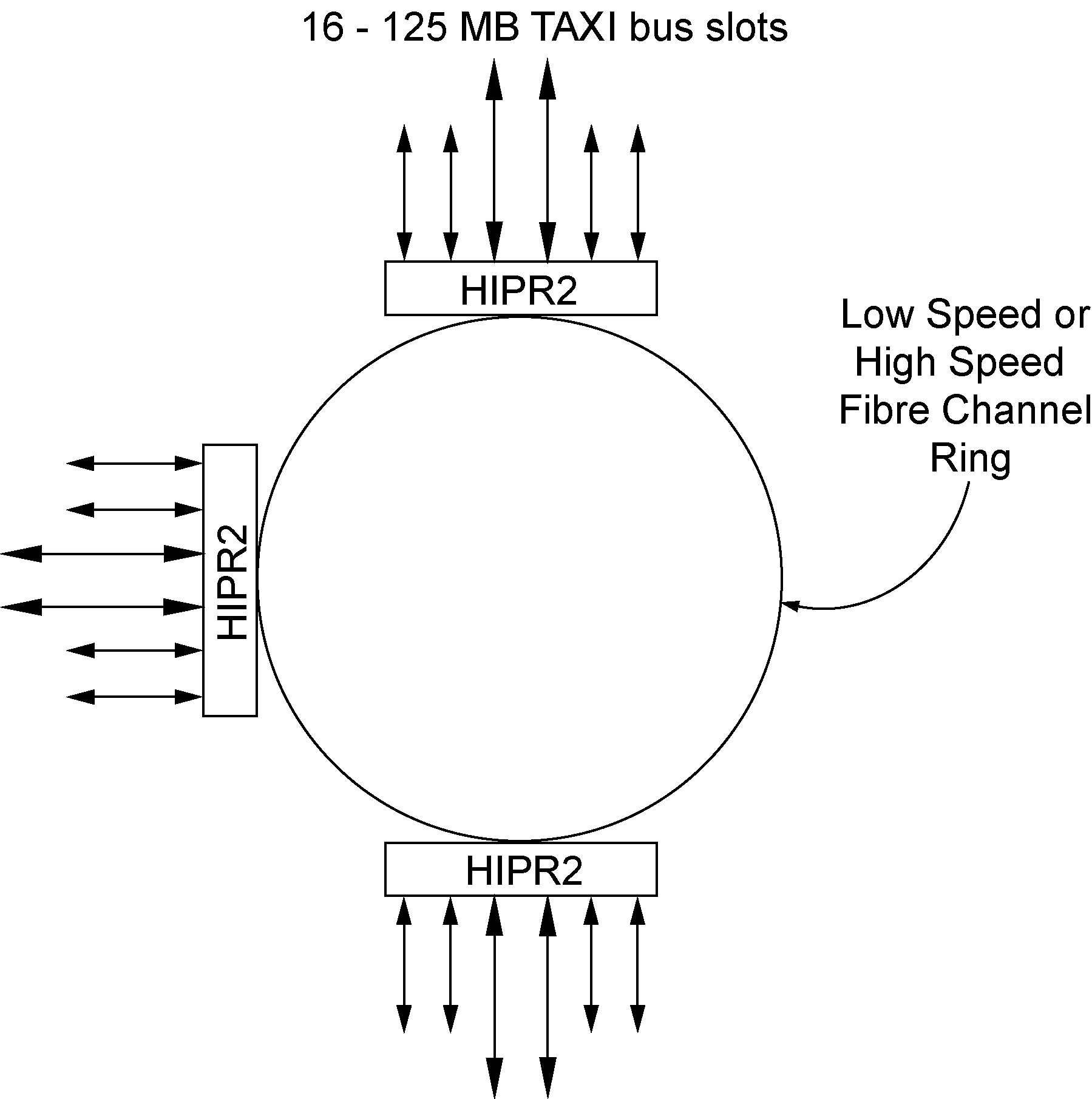
The inter-shelf ring connects the shelves together and HIPR2 acts as a gateway between the intra-shelf IMT bus, running at 125 Mbps, and the inter-shelf Fibre channel ring operating at a high rate (2.5 Gbps). HIPR2 retains the high speed 1Gb Fibre Channel ring as a way to ensure interoperability with other HIPR2 equipped shelves. After HIPR2 recognizes that data from the high speed ring is destined for its shelf address, the data is immediately switched to the correct card within the shelf rather than traversing the intra-shelf IMT bus, running at 125 Mbps. The HIPR2 allows more bandwidth than in the HMUX-based ring architecture.
As shown in Figure 3-24, in a same topology where all HIPR2 is used in an EAGLE the Fibre channel ring runs at either the low or high speed.
Figure 3-24 HIPR2 Switch Same Topology
The switched interface to each card is at 125 Mbps, the same speed as the intra-shelf IMT bus. This switched architecture has an inherent reliability advantage of point to point connections within the shelf. A ring can be broken, potentially causing all cards on the ring to be affected. However, a switched architecture automatically isolates a problem to a specific data path which immediately determines which card is experiencing problems. Trouble shooting and debugging are greatly enhanced. For example, corrupted packets can be isolated quickly because there is only a single path per card rather the multiple paths possible in a ring.
All routing decisions are controlled by the network processor on the HIPR2 card. A core processor performs the switching function. This allows future upgrades without changes to the hardware.
Upgrade Considerations
The HIPR2 card is compatible with the obsoleted HIPR card slot and can be fielded with any version of either the control or extension backplanes compatible with the obsoleted HMUX. One bus is taken out of service and upgraded to HIPR2s and then brought back online. This upgrade cycle is repeated on the second bus to get both busses upgraded. HIPR2 interfaces and operates with all the same cards that HIPR had been used with.
Two HIPR2 modules are required in shelves equipped with high-performance LIMs, such as the High-Capacity MIM, and for interfacing to application servers (such as the Tekelec 1x00 series of Application Servers) through IMT Bridge and IMT PCI modules. HIPR2 requires all other shelves be equipped with either all HIPR2 cards. High-rate (2.5 Gbps) operation requires that all shelves within EAGLE be equipped with HIPR2, IMT interface cables upgraded to support new high-speed Fibre-channel, and a system FAK installed to allow the high-rate channel.
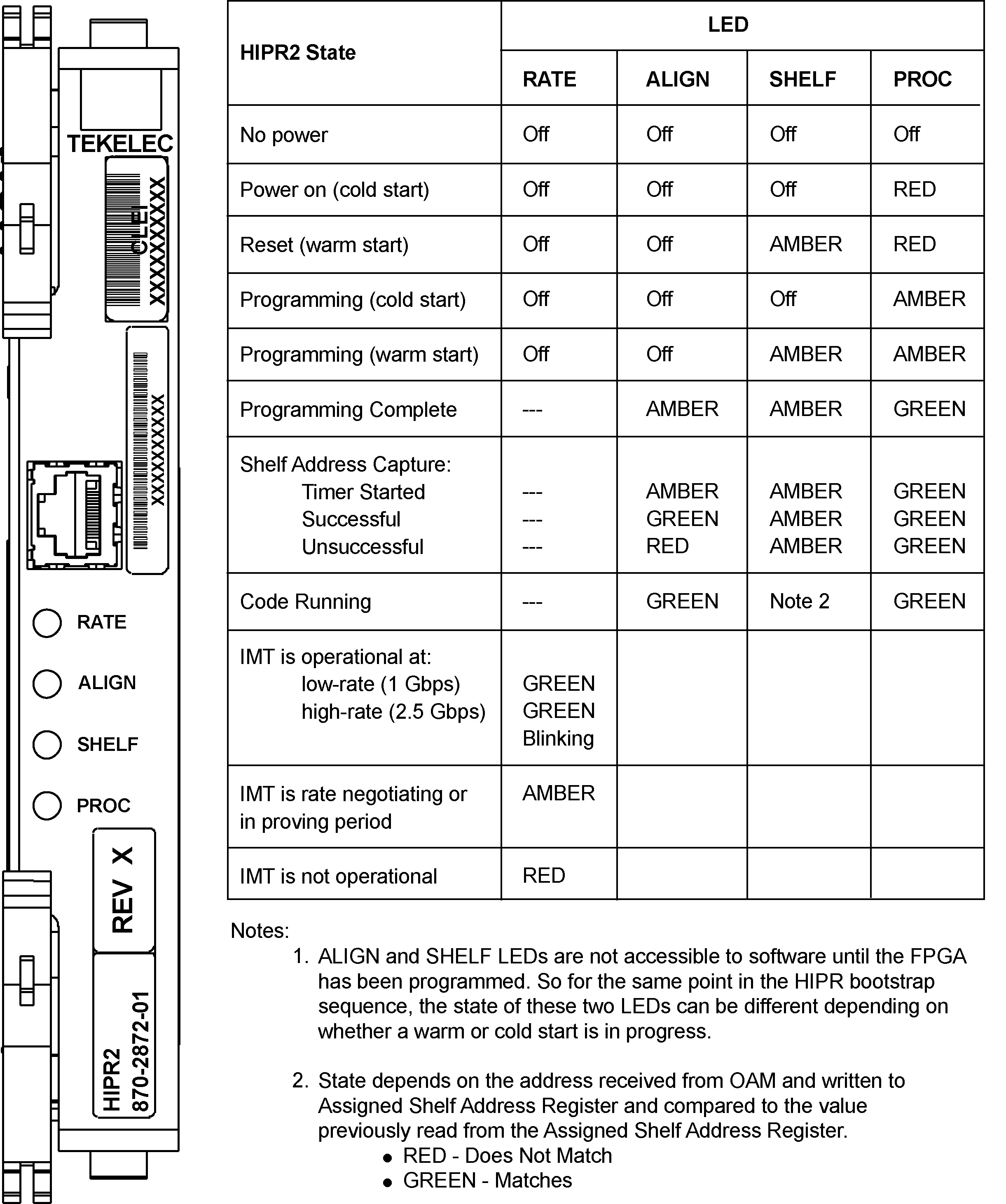
LEDs
On the front edge of the HIPR2 card, there are four Light Emitting Diodes (LED) that provide status. Each LED has a red, green, or amber illumination state. The RATE LED indicates the IMT bus condition. The ALIGN LED indicates code initialization and programming status. The SHELF LED indicates HIPR2 running and shelf ID address condition. The PROC LED indicates state of the HIPR2 processor.
Figure 3-25 summarizes the use of the front-panel LEDs.
Figure 3-25 HIPR2 LEDs
Cabling
As of Release 46.4, the EAGLE will only operate at the HIPR2 card high rate (2.5 Gbps). High-speed Fibre-channel cables (P/N 830-1344-XX, length dependent upon site requirements) must replace existing cables (P/N 830-1141-xx/830-0221-xx) in order for HIPR2 high-rate operation and Release 46.4 compatibility.
Technical Specifications
Table 3-3 HIPR2 Technical Specifications
| Physical Characteristics | |
|---|---|
|
Height |
7.7 in. (18.3 cm) |
|
Width |
1.8 in. (2 cm) |
|
Depth |
12.8 in. (32.5 cm) |
3.7.2 E5 Maintenance and Administration Subsystem Processor (E5-MASP) Card
The Maintenance and Administration Subsystem Processor (E5-MASP) cards contain all of the necessary logic to perform both application and communication processing of the data streams provided by the EAGLE. The cards provide connections to the IMT bus through the backplane and all of the necessary logic to perform both application and communication processing of the data streams through the EAGLE. The E5-MASP cards contains one fixed drive and USB connectors for two removable drives. The USB storage media in the flush-mounted USB port of the MASP card can be used for backups.
3.7.2.1 Requirements and Dependencies
- Requires an E5-MDAL in the control shelf.
- Requires HIPR2 to be active on both IMT buses in the control shelf.
Note:
HIPR2 requires all other shelves to be equipped with all HIPR2 cards. - The E5-MASP operates in backplanes 850-0330-03, 850-0330-04, 050-0330-06, 850-0330-07, or 7333412. See "Hardware Baseline Table" in Release Notes for compatible backplane part numbers.
- Does not require a fan tray assembly for thermal management.
Figure 3-26 E5-MASP Card -01
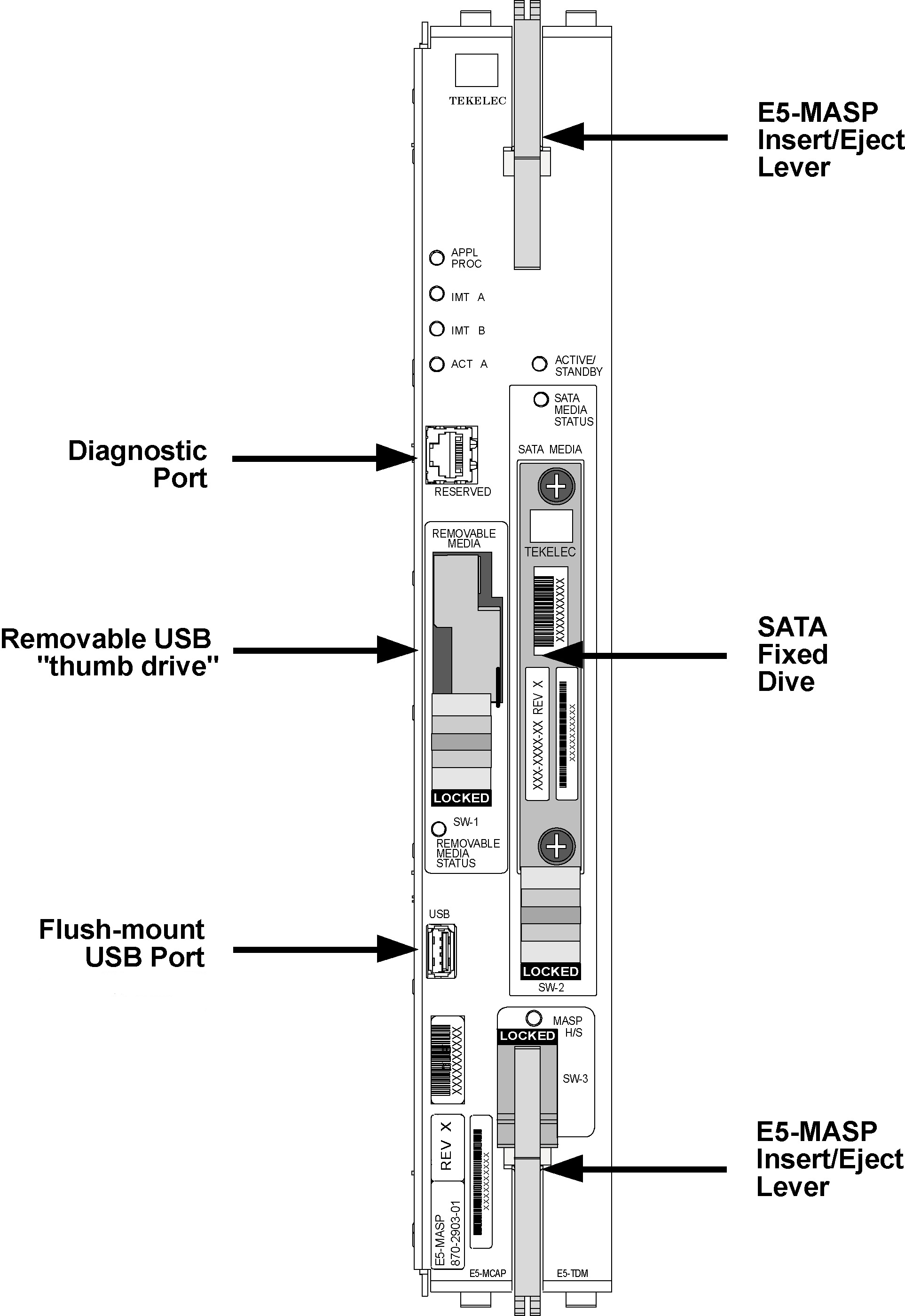
Figure 3-27 E5-MASP Card -02
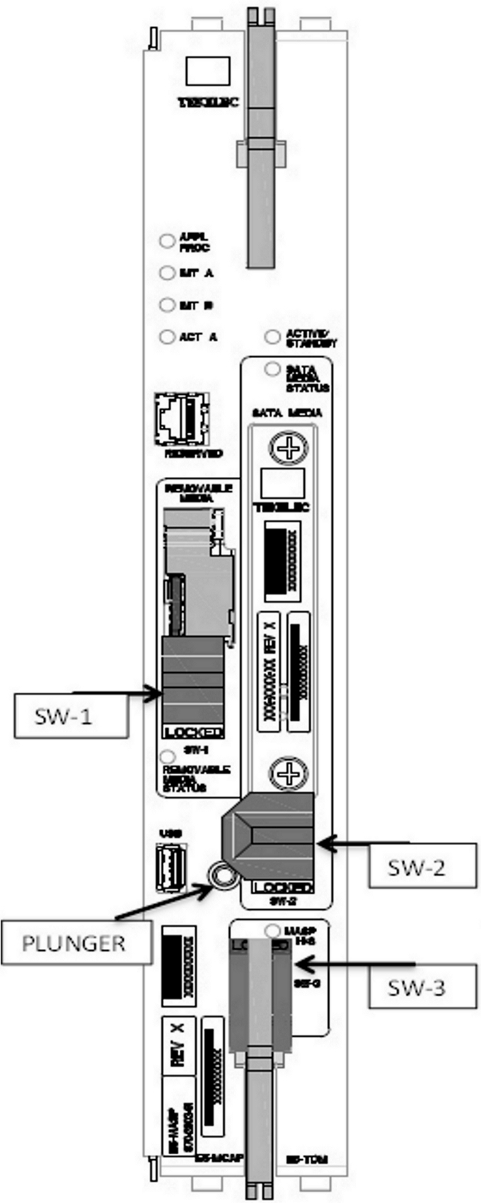
SW-1: Used to activate or de-activate Removable USB "thumb drive." The locked position activates the switch.
SW-2: Used to activate or de-activate hard drive. The locked position activated hard drive. The plunger must be depressed before the switch can be unlocked, which de-activates hard drive.
SW-3: Used to activate or de-activate the card and lock or unlock the lower E5-MASP Insert/Eject lever. The locked position activates the card and locks the lever.
3.7.2.2 E5-MCAP
The E5-MCAP card is equipped with 4 GB of physical application processor memory. The primary data interface to the E5-MCAP is RS-232 interfaces (i.e.: terminals) through the E5-TDM.
The E5-MCAP card contains one latched USB port for use with removable flash media (“thumb drive”), and one flush-mounted USB port for use with a plug-in flash drive. The removable media drive is used to install and back up customer data. The flush-mounted USB port is used for upgrade and could be used for disaster recovery. The removable flash media is used as a replacement for the legacy Magneto-Optic (MO) Drive. The E5-MCAP card is a replacement for the obsoleted legacy GPSM-II card used for the MCAP function.
3.7.2.3 E5-TDM
The E5-TDM card contains four major subsystems: the Terminal Processor Subsystem, the System Clock/Control Subsystem, the SATA Subsystem, and a Power Subsystem. These subsystems provide the EAGLE 5 with 16 user-accessible terminals, distributes Composite Clocks and High Speed Source clocks throughout the EAGLE 5, distributes Shelf ID to the EAGLE 5, and disk storage for an E5-MCAP card. The E5-TDM card provides an interface to the E5-MDAL card for system alarms.
The E5-TDM card contains one fixed solid-state SATA drive that is removable and used to store primary and backup system databases, measurements, and Generic Program Loads (GPLs).
3.7.2.4 E5-TDM Functions
System Clock Interface
The primary purpose of the Clock LCA is to derive and/or distribute the system clocks for the EAGLE. There are two system clock outputs: the TEKCC clock and high-speed E1/T1 clock. The external clock sources are a BITS or composite clock input, a high-speed E1/T1 clock input, and a derivation of an E1/T1 clock generated on the E5-TDM. The terminal processor on the E5-TDM selects which source clock is used to derive and/or distribute the system clocks. Each external source has a primary and secondary that is received, verified and validated. The E5-TDM automatically switches the clock source between the primary and the secondary if the current source fails validation.
The BITS or composite clock is used to generate the TEKCC clock output. The high-speed clock input is distributed via the high-speed clock output. The terminal processor can force a switch of the system clock source between the primary and secondary clocks, or select the local oscillator as the system clock source. The local oscillator only generates a TEKCC output. It cannot generate a high-speed E1/T1 clock output. Therefore, if the terminal processor selects the local clock and there is no high-speed clock input present, there will be no high-speed clock output.
The terminal processor can also select to derive the system clocks internally on the E5-TDM. This is known as the Global Timing Interface. A customer needs only to have an E1/T1 data stream as input to the E5-TDM. The E5-TDM will generate and distribute the TEKCC and high-speed E1/T1 clocks to the system.
Time Slot Counter (TSC) Synchronization
The Time Slot Counter (TSC) Synchronization feature is an advanced function enabled in all LIMs. The TSC Synchronization feature does not require any physical hardware changes to any of the boards in the EAGLE. TSC Synchronization is an optional feature for the EAGLE that will allow all cards in the system, which contain a Time Slot Counter, to synchronize with one another. The ability to have synchronized timing between cards is used in applications such as system wide message time stamping.
The TEKCC output includes Time Slot Synchronization information. In the EAGLE system, it is possible for the occurrence of the TSC Sync pulse to differ in time between the Active and the Standby E5-TDM. This difference is known as TSC skew. This skew must be detected and eliminated so that cards can switch between the two clocks and stay synchronized to the rest of the system. In the E5-TDM, the elimination of TSC skew is accomplished in hardware, a LIM card does not detect TSC skew. If skew occurs, hardware detects and corrects this and alerts the system that this condition has occurred.
- HCMIM, E5-E1T1-B, E5-ENET, E5-ATM-B
Source/Follower Control
The terminal processor can switch the status of the E5-TDM card from source to standby modes. The terminal processor can determine the state of the E5-TDM (active or standby) and can also force a switchover from active to standby.
Alarm Interface
The Alarm Interface gives the terminal processor visibility to E5-MDAL Alarms, External Alarms, and Customer Alarms. The interface is split into two parts: the terminal processor interface and the physical interface. The terminal processor interface contains registers to update E5-MDAL alarms and status registers to read E5-MDAL alarms. It also contains external and customer alarm registers.
The physical interface is made up of a bidirectional I2C interface to the E5-MDAL and direct connection to opto-isolator outputs for external and customer alarms. The physical interface provides input data to the registers which the terminal processor can read. The physical interface also provides a way for the E5-MDAL alarm update data to be sent to the E5-MDAL.
Shelf ID UART Interface
The Clock LCA implements a 9-bit UART, which is used to transmit Shelf ID information to each EAGLE shelf. The terminal processor selects which shelf to transmit the information.
3.7.2.5 Thermal Management
The E5-MASP provides thermal management and alarming provisions to protect the card from damage due to overheating. The E5-MASP contains a thermal monitor with software selectable thresholds for temperature abnormal levels. Threshold crossings generate alarms and impair card operations. These alarms require the mitigation of the temperature rise to resume normal card operations interrupted by the threshold crossings. The E5-MASP is designed to operate in the EAGLE shelf with natural convection cooling and does not require a fan tray for cooling.
Table 3-4 Thermal Alarm Conditions
| Board Temperature | E5-MASP Actions |
|---|---|
|
Temp Level 1 Exceeded |
Major alarm raised |
|
Temp Level 2 Exceeded |
Critical alarm raised; the application software responds to the notification by either preventing database updates or failing over to the stanby |
|
Temperature abated |
Application re-allows database updates; Normal operation restored |
|
Thermtrip - shutdown temperature exceeded |
CPU shuts down automatically. Card must be reseated to restore operation once temperature returns to normal operating conditions |
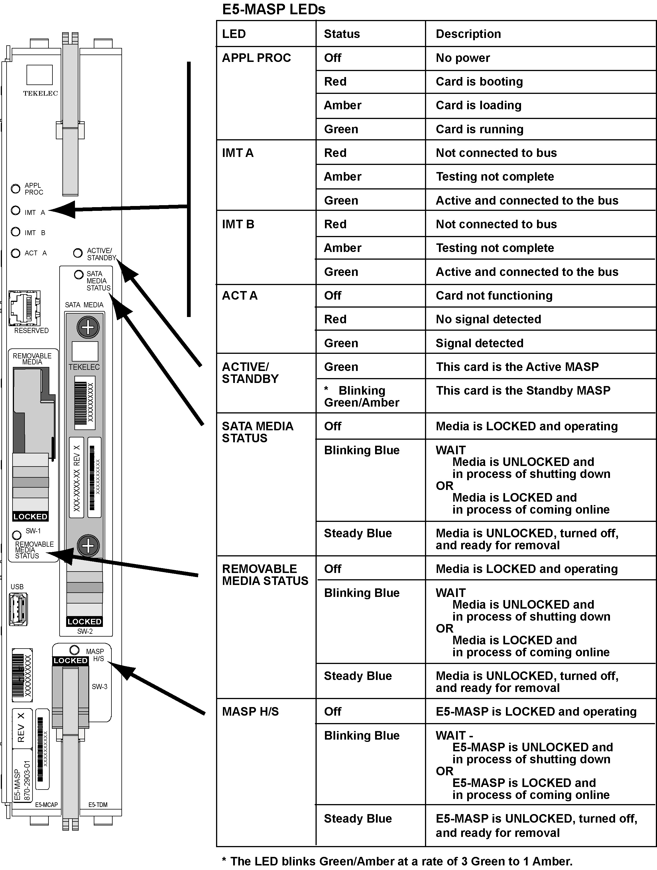
3.7.2.6 Switches and LEDs
The E5-MASP card provides faceplate switch interfaces for the removable drive (SW1), the fixed SATA drive (SW2), and the card (SW3). Each switch is used to notify software that the corresponding item is about to be unplugged or is plugged in and ready for use. Software may use this signal to gracefully shut down the card. An associated LED for each corresponding item indicates when it is safe to remove the item.
The E5-MASP card has six LEDs visible on the front of the card.
Figure 3-28 shows the LED status and description.
Figure 3-28 E5-MASP LEDs
3.7.2.7 Cabling and Technical Specifications
The E5-MASP card utilizes an RS-232 cable for manufacturing and customer service installation diagnostics. The cable part number is 830-1327-XX.
Table 3-5 E5-MASP Technical Specifications
| Physical Characteristics | |
|---|---|
|
Height |
14.43 in. (36.65 cm) |
|
Width |
2.06 in. (5.23 cm) |
|
Depth |
12.80 in. (32.51 cm) |
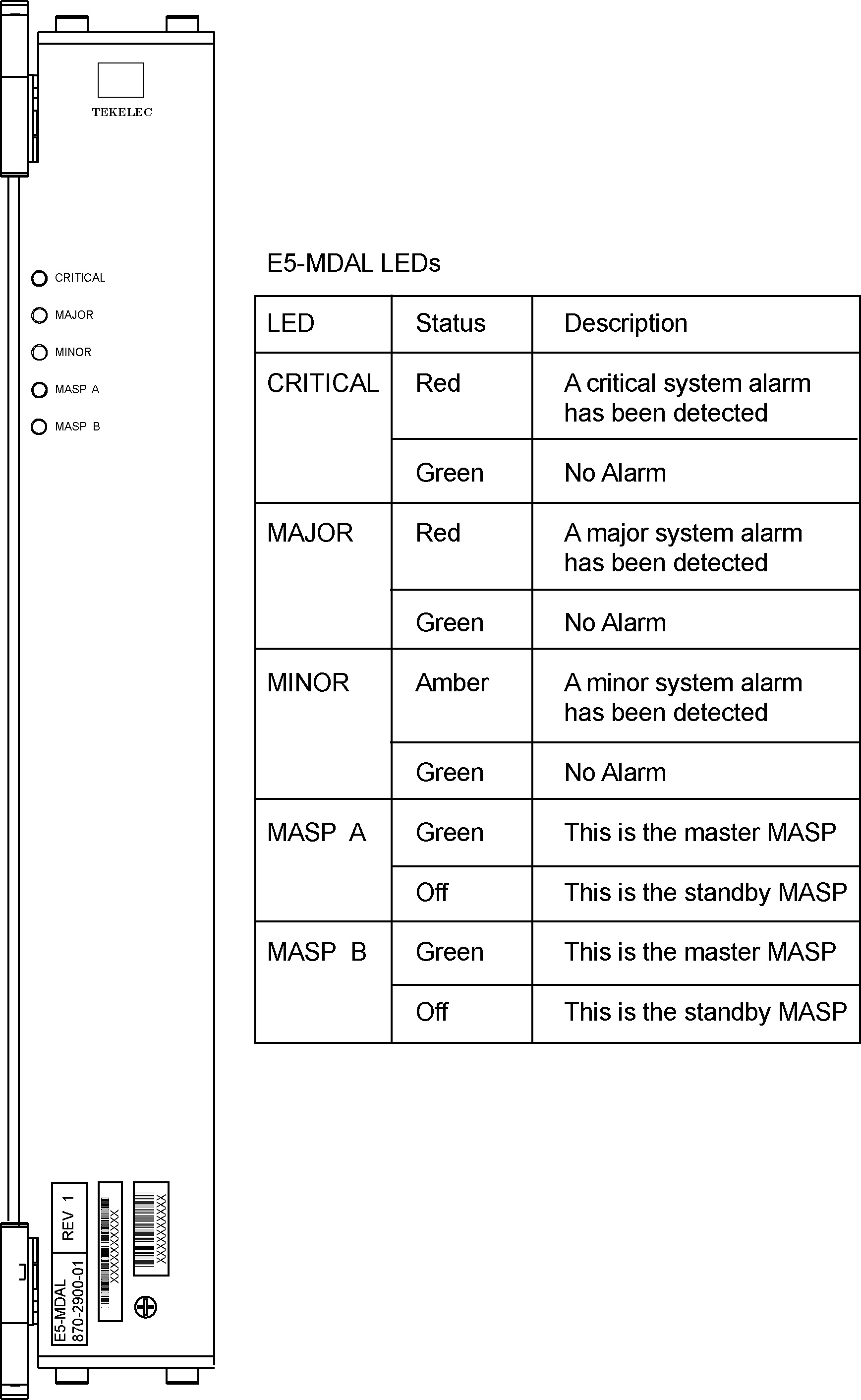
3.7.3 E5-MDAL
The E5-MDAL card processes alarm requests, provides general purpose relays, and provides fan control. There is only one E5-MDAL card in a control card set and it is shared between two E5-MASP cards. The E5-MDAL card is located in slots 1117 and 1118 of the control shelf.
Critical, major and minor system alarms are provided for up to 6 individual racks. In addition to the 3 system alarms, the E5-MDAL card provides the system audible alarm. All alarms are software controlled.
The E5-MDAL card provides control of fans on a per frame basis. The control logic allows for each fan relay to be set individually.
The E5-MDAL card does not contain a disk drive.
3.7.3.1 Alarms
Alarms are grouped into four categories: Rack, Remote Maintenance Center (RMC), Local Maintenance Center (LMC), and the Row End Panel. Critical, major and minor system alarms are provided for up to 6 individual racks. In addition to the 3 system alarms, the E5-MDAL card provides the system audible alarm. All alarms are software controlled.
Relays on the E5-MDAL provide switching for all of the alarm circuits. Regardless of which E5-MASP is primary, the current state of the relays is read by both TDM_A and TDM_B alarm buses on the E5-MDAL. General Purpose Relays reset signals have not been carried over from the obsoleted legacy MDAL to the E5-MDAL. Critical relays are wired such that they are in the alarming state when the E5-MDAL is not powered.
Alarm indicator lights are provided in the Row End Panel, Fuse Panels, and E5-MDAL Card panel. The major and minor alarms are only active if there is a request from the E5-MASP and the E5-MDAL indicates that at least one of the E5-MASPs is sane. A critical alarm is generated if there is a request from the E5-MASP or the E5-MDAL card indicates that both E5-MASPs are insane or the E5-MDAL card loses power. The RMC signals are gated by the AlarmTransfer signals from the primary E5-MASP. When the AlarmTransfer signal is active, the RMC signals are set to the output relays. When the AlarmTransfer signal is inactive, the RMC alarm signals are blocked. Optocouplers on the RMC alarms sense current when the alarms are active. If the alarm is active and there is no current sensed then it is assumed that the bulb/led on the row end panel is either burned out or missing.
3.7.3.2 Fan Control
Note:
The control logic allows the each optocoupler to be read individually.3.7.3.3 LEDs
There are 5 bicolor LEDs on the E5-MDAL that are controlled by the software in the E5-MASP. The critical, major and minor system alarm LEDs have four states per LED, which can be set by the E5-MASP. They are not tied to the alarm logic and are completely under control of the E5-MASP software. The MASP A and MASP B LEDs indicate which E5-MASP is primary. Located on the E5-MDAL is a Sonalert electronic audible device. The buzzer is activated if both E5-MASPs are insane or if there is sanity and a request is made by the primary E5-MASP.
Figure 3-29 E5-MDAL LEDs
3.7.4 Time Slot Counter Synchronization
The Time Slot Counter (TSC) Synchronization feature is an advanced function enabled in all LIMs. The TSC Synchronization feature does not require any physical hardware changes to any of the boards in the EAGLE. TSC Synchronization is an optional feature for the EAGLE that will allow all cards in the system, which contain a Time Slot Counter, to synchronize with one another. The ability to have synchronized timing between cards is used in applications such as system wide message time stamping.
The TSC Synchronization feature uses E5-OAM cards. The EAGLE must use an external BITS clock so that the system A and B clocks remain synchronous to each other. If either of the TDMs provides its internal clock to the system instead of the BITS clock, the A and B clocks may drift apart and introduce skew into the system.
After the TSC Sync feature is enabled there may be skew between the A clock and B clock TSC Reset Events. This skew must be detected and eliminated so that cards can switch between the two clocks and stay synchronized to the rest of the system. All cards with a TSC have a Skew Interrupt and the Skew Count register.
TSC Sync affects all EAGLE cards that contain a Time Slot Counter. This includes:
- E5-E1T1-B, E5-ENET-B, SLIC
- E5-ATM-B
3.7.5 Link Interface Modules
Caution:
After the frame has been shipped or moved, prior to applying power, remove all cards.Caution:
Reset all cards carefully to avoid possible faulty connections. All cards are hot swappableThe Link Interface Module (LIM) provides access to remote SS7, IP and other network elements, such as a Signaling Control Point (SCP). The LIMs consist of a main assembly and possibly, an interface applique board. These appliques provide level one and some level two functionality on SS7 signaling links. The types of LIMs presently available are:
- E5-E1T1-B (P/N 870-2970-xx) cards.
- E5-ATM-B (P/N 870-2972-xx) cards.
Maximum Numbers of Links
A maximum of 2800 links can be configured in the EAGLE depending on the hardware, software release level, and features that are installed. A mixture of high-speed and low-speed signaling links is supported.
Note:
If the addition of either a low-speed signaling link or a high-speed signaling link exceeds the total number of low-speed and high-speed signaling links allowed in the system, the ent-slk command is rejected. The addition of a high-speed signaling link decreases the number of low-speed signaling links that can be supported by the system.Table 3-7 describes the required hardware for the maximum number of links with different configurations.
Note:
Table 3-7 lists EAGLE base hardware requirements only. For complete provisioning rules and requirements, including tables listing all link types see Database Administration - SS7 User's Guide.LIM Main Assembly
Table 3-7 Hardware Requirements-Maximum Number of Links
| Number of Links | Required Hardware |
|---|---|
|
Up to 500 Links Note: A Maximum of 42 High-speed LIM cards (of which up to 41 can beIPLIMx cards) can be installed |
HIPR2 cards on the IMT buses 2-port LIM cards or multi-port LIM cards (MPLs) Installed according to the provisioning rules for a system with up to 500 links in Database Administration - SS7 User's Guide. |
|
From 501-700 Links |
HIPR2 cards on the IMT buses Enough E5-E1T1-Bs to bring the total number of signaling links above 500, up to 700. Installed according to the provisioning rules for a system with 700 links in Database Administration - SS7 User's Guide. |
|
From 701--1500 Links |
Enough E5-E1T1s to bring the total number of signaling links above 500, up to 700. Installed according to the provisioning rules for a system with 700 links in Database Administration - SS7 User's Guide. |
|
From 1500 -- 2800 Links |
Enough E5-B cards to bring the total number of signaling links to 2800. Installed according to the provisioning rules for a system with 2800 links in Database Administration - SS7 User's Guide. |
Cam-out/lock-in levers, mounted on the front edge of LIM cards, (the exception being E1) assist in the insertion and the removal of the card from the shelf.
The figures below show the E5-B based LIM cards.
All four PCB assemblies have the same basic functions:
- Intel Dual Core processor: one core is used as the applications processor and the other core is used as the communications processor
- An Inter-processor Message Transport (IMT) interface that provides two 125 Mbps communications links that provide communications between modules
- –48VDC/+5VDC and –48VDC/+3.3VDC DC to DC power converter units
Figure 3-30 E5-ATM-B Card
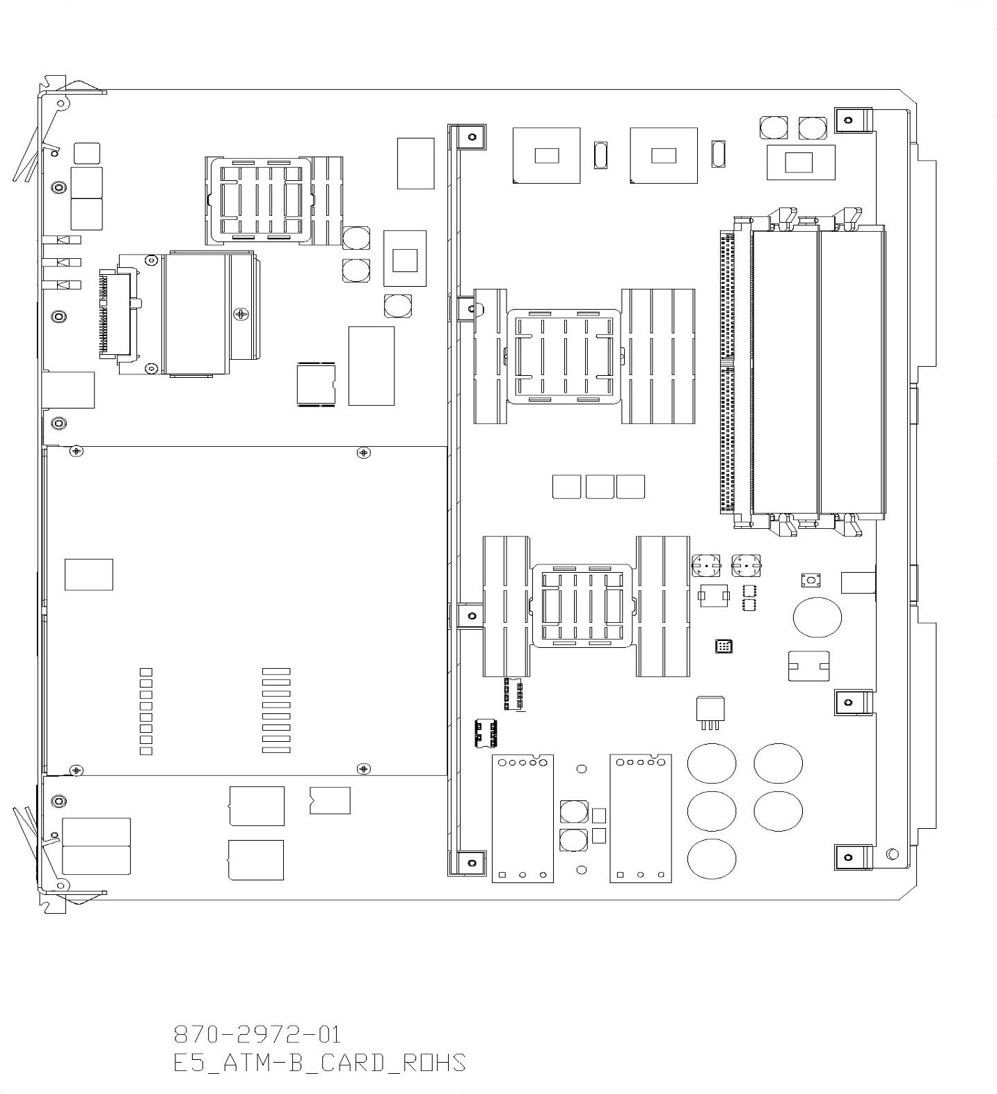
Figure 3-31 E5-E1T1-B Card
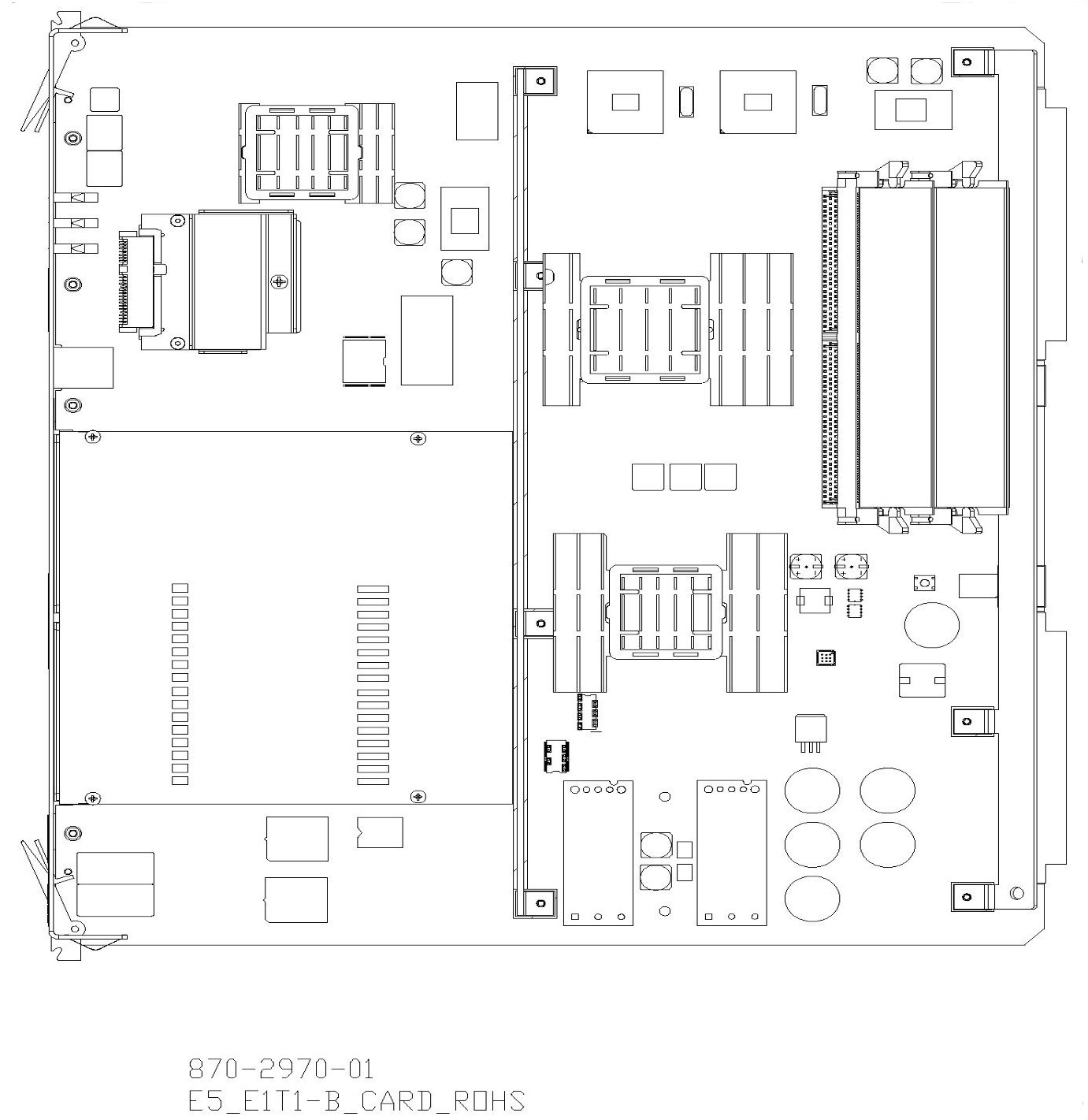
Figure 3-32 E5-ENET-B Card
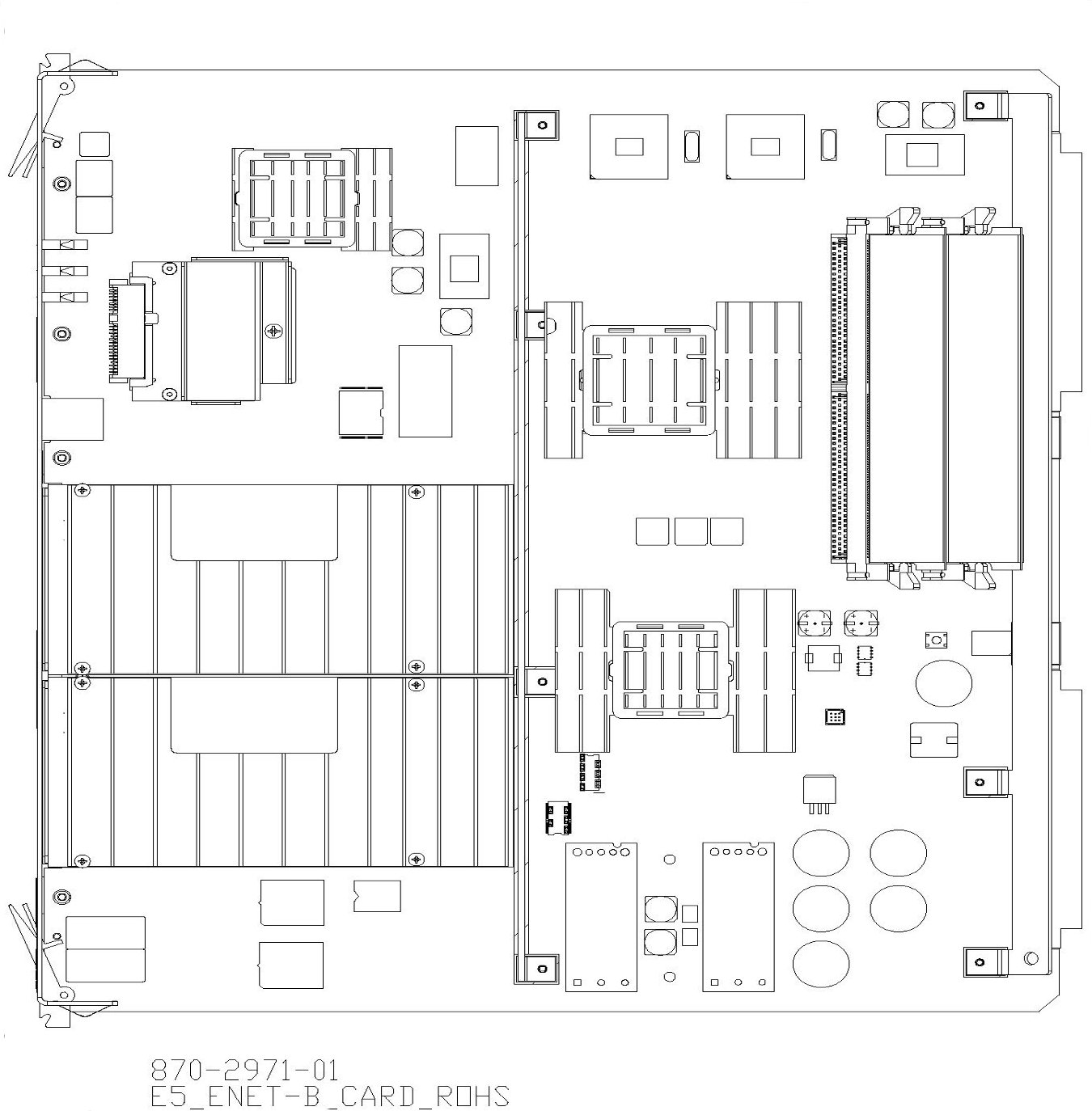
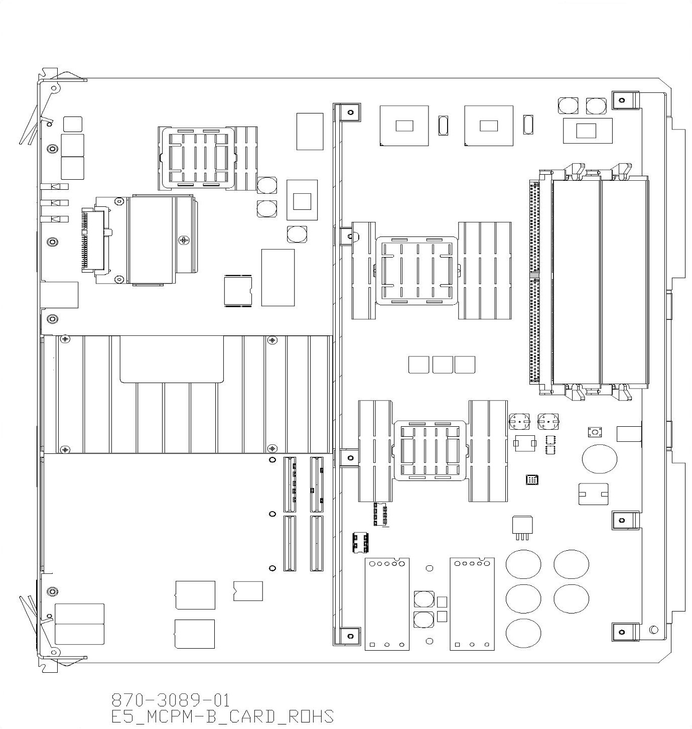
Figure 3-33 E5-MCPM-B
Applications Processor
The Application Processor (AP) section of the LIM interfaces and controls the operation of the interface applique. The AP’s operations are controlled by one core of the Intel Dual Core processor and peripherals.
Communications Processor
The Communications Processor (CP) is made up of one core of the Intel Dual Core Duo processor and peripherals. The CP section of the LIM controls the flow of transmit/receive data to and from the Inter-processor Message Transport (IMT) buses.
In the receive direction, the CP writes a receive initialization command to the IMT bus. The data packet is checked for the destination. If its destination is this LIM, the format is checked and a Cyclic Redundancy Check (CRC) is performed. The packet is then transferred to the CP memory by Direct Memory Access (DMA).
In the transmit direction, the CP forwards a packet along with 2 CRC bytes, calculated by the IMT circuitry, to the HIPR2 cards for transmission.
The CP also controls the selection of the IMT buses, A or B. In the other direction, the CP forwards data received from the IMT buses through the AP to the interface port (DB15) connector on the shelf backplane.
The CP is interrupt driven. Eight levels of the interrupts initiated by the IMT, the AP, and the MAS, are administered by a Programmable Interrupt Controller (PIC).
Inter-processor Message Transport
Each LIM unit has two Inter-processor Message Transport (IMT) interface circuits, IMT A and IMT B. The redundant IMT buses are used to transport:
- Generic Program Loads (GPLs) to various circuit cards
- All SS7 and traffic between circuit cards
- Maintenance traffic within the system
In the receive direction, a data packet is checked to see if it is destined for this particular LIM. If it is, the packet is checked for format and a cyclic redundancy check is performed. The packet is then transferred to the CP memory by Direct Memory Access (DMA). If the packet is not destined for this LIM, it is sent back onto the IMT bus towards the next module.
In the transmit direction, the Cyclic Redundancy Check (CRC) is calculated for a packet and the packet is transmitted through the HIPR2 cards to the IMT bus.
Power Converter Unit
LIM power is provided by two DC to DC converters that convert the –48VDC supplied to the system to +5VDC and +3VDC needed to power the LIM components.
Test and Maintenance Features
Colored LEDs are mounted on the front edge of the printed circuit board as LIM status and alarm indicators.
3.7.6 Measurements Collection and Polling Module
The MCPM is an E5-MCPM-B card running MCPHC GPL.
Note:
The E5-MCPM-B card is a requirement for the FTP measurements feature. The FTP measurements feature uses the E5-MCPM-B ethernet ports to transfer measurements information directly to a FTP server.On the front edge of the MCPM card, there are five Light Emitting Diodes (LED) that provide status. The MCPM LEDs have four illumination states: red, amber, green, or off. The Application processor LED is off if -48VDC is not supplied. The Application Processor LED is red while booting, amber while loading, and green when the application is running. The IMT A and B LEDs indicate whether the MCPM is active on the A or B buses. IMT LED red—the card is off the bus, IMT LED amber—MUX card on the same shelf is seated and not inhibited; bus not available, IMT LED green—the card is active on the bus. The PORT A and PORT B LEDs are illuminated green when the A or B port is active.
3.7.7 E5-ATM-B Module
The E5-ATM-B card (P/N 870-2972-01) is a single slot card providing ATM over E1 and T1 connectivity for EAGLE control and extension shelves.
Note:
Throughout this document, the term E5-ATM refers to the E5-ATM-B card (P/N 870-2972-01) card.Note:
All E5-based cards require HIPR2. For more information, see High-Speed IMT Packet Router 2.- SS7 Link, ATM over T1 (ANSI)
- SS7 Link, ATM over E1 (ITU)
- TVG or MFC based load sharing
- Integrated Sentinel (e-route)
- Integrated Message Feeder
- Higher throughput than current HCAP-based LIMATM and LIME1ATM cards
- Automatic on/off CRC4 detection for E1 framing (default is on)
- Three ATM signaling links operating at 1 Erlang
- BICC support
- Thermal protection
- Requires HIPR2 in the shelf where the E5-ATM-B resides.
- E1 or T1 support, but will not support both physical port types on a single card simultaneously
- The E5-ATM-B requires a fan tray assembly for thermal management.
- Can interoperate with E1-ATM
- Is a hot-swap compatible replacement for the HCAP-based
LIMATM and LIME1ATM cards
Note:
Hot-swap is limited to one interface, but the second and third link can be provisioned once E5-ATM-B is installed. The Port B connector on the backplane may be used for link connectivity. To utilize the Port B connector on the backplane, a cable adapter (P/N 830-1342-05) and an additional cable are required. - The E5-ATM-B requires Message Flow Control (MFC) feature
- The E5-ATM-B does not support TVG
- E5-ATM-B modules require a fan tray assembly for thermal management. Be sure to install the fan assembly before installing the E5-ATM-B card. See "Hardware Baseline Table" in Release Notes for compatible fan assembly part numbers.
Thermal Management
The E5-ATM includes thermal management and alarming provisions to protect the card from damage if environmental conditions hinder thermal stability.
When the CPU temperature rises above nominal range and exceeds a thermal threshold (Temperature Level1) a major alarm is raised against the card. When the temperature returns to its nominal range (below Temperature Level1) the alarm is automatically cleared.
If the temperature continues to increase and exceeds a second thermal threshold (Temperature Level2) a critical alarm is raised against the card. When this second thermal event occurs, the result is a local processor outage (LPO) and traffic is redirected to other cards (changeover), if possible. For ATM links, an LPO will take the links out-of-service. If the temperature recedes under the Temperature Level2 threshold, the LPO condition is cleared and the links can begin operation again.
If the CPU temperature goes above operating limits (approximately 99ºC), the CPU will halt and the card will shut itself down to prevent permanent, catastrophic damage. In the event of thermal shutdown all processor activity will cease. If thermal shutdown occurs, the E5-ATM must then be reseated and allowed to load in order to clear the alarm and resume operation.
If the CPU temperature goes above operating limits (approximately 95ºC for E5-ATM or 90ºC for E5-ATM-B), the CPU will halt and the card will shut itself down to prevent permanent, catastrophic damage. In the event of thermal shutdown all processor activity will cease. If thermal shutdown occurs, the E5-ATM must then be reseated and allowed to load in order to clear the alarm and resume operation.
Table 3-8 identifies the appropriate responses.
Table 3-8 Thermal Alarm Conditions
| Board Temperature | Actions |
|---|---|
|
Temp1 Exceeded |
Major alarm raised |
|
Temp1 Exceeded |
Major alarm raised; PST/SST of card transitions to IS-ANR/Restrict |
|
Temp2 Exceeded |
Critical alarm raised; failover initiated, traffic rerouted |
|
Temp2 Exceeded |
Critical alarm raised; failover initiated, traffic rerouted; PST/SST of card remains in IS-ANR/Restrict |
|
Temperature abated |
Normal operation restored |
|
Thermtrip - shutdown temperature exceeded |
CPU shuts down automatically. Card must be reseated to restore operation once temperature returns to normal operating conditions |
The thermal thresholds (Temperature Level1 and
Temperature Level2) are user configurable. The user configurable T1and T2
values will always be less than or equal to the T1 (max) and T2 (max) defined
for a particular board type respectively. See
Table 3-9
and the
chg-th-alm command for more details on
thermal thresholds.
Table 3-9 T1 and T2 temperature thresholds
| Cards | T1 Max (in Celsius) | T2 Max (in Celsius) | User Configurable T1 range (in %) | User Configurable T2 range (in %) |
|---|---|---|---|---|
| E5-ATM | 92 | 95 | (73-92)% of T2 max | (74-100)% of T2 max |
| E5-ATM-B | 83 | 90 | (73-92)% of T2 max | (74-100)% of T2 max |
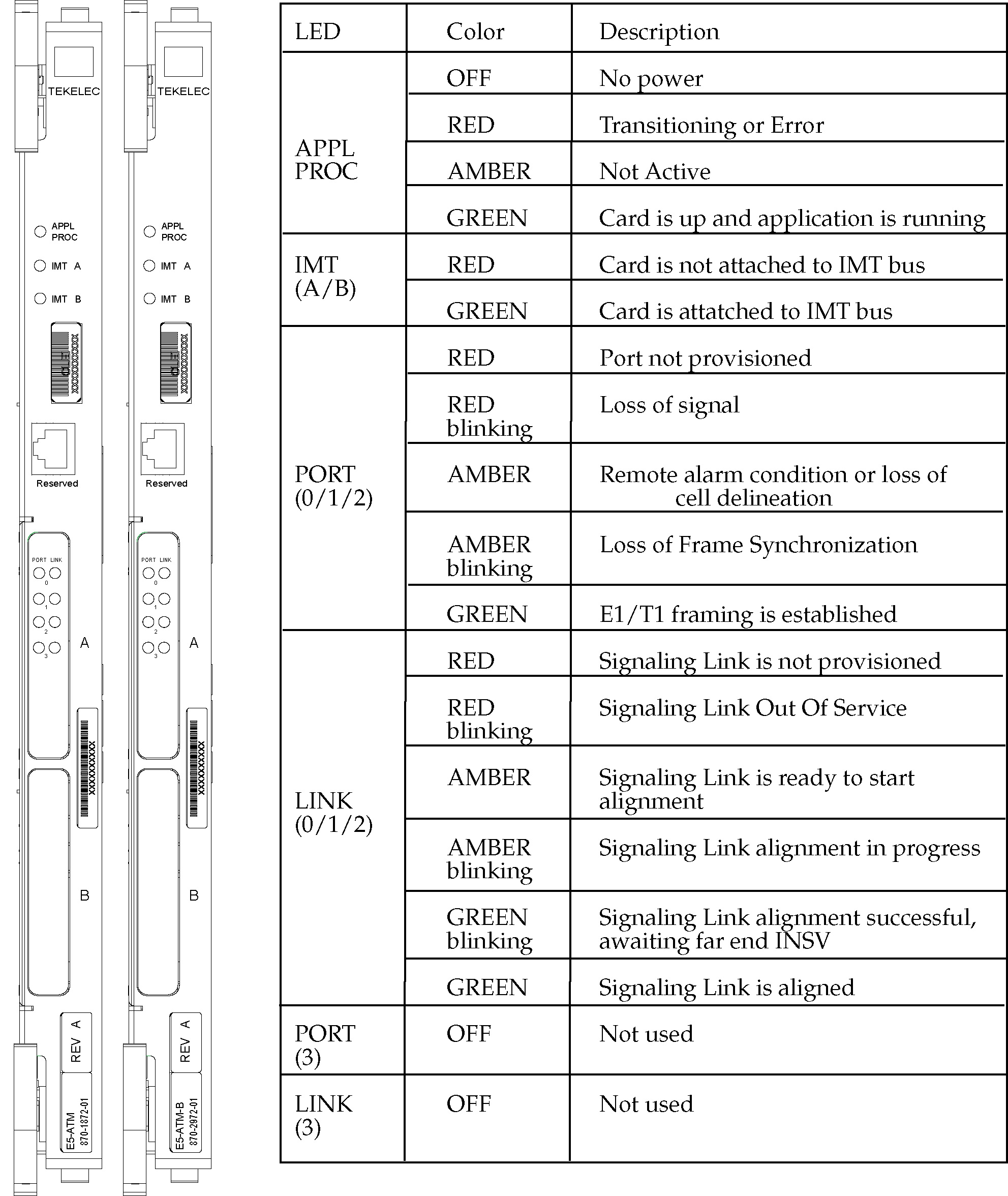
LED Indicators
The E5-ATM includes three front panel indicators (LEDs) for APPL Proc operation, IMT A, and IMT B status. In addition, four front panel LED Link/Activity indicators (two for each IP port used). Figure 3-34 shows the LEDs and provides a description of indications.
Figure 3-34 E5-ATM-B
Interface Adapter
The E5-ATM-B provides connectivity for two E1/T1 ports on the Port A backplane connector, allowing up to two links that may be provisioned. Both E1/T1ports can be accessed with a 2-port or 4-port cable. An interface adapter (P/N 830-1342-05) allows the two ports to be physically split to two different cables/patch panels. If it is desired to move the second E1/T1 port to the Port B backplane connector, then an adapter and another cable (1-, 2-, or 4-port) must be used.
- 1-port connectivity (P/N 830-0849-XX or P/N 830-1184-XX)
- 2-port connectivity (P/N 830-0622-XX or P/N 830-1233-XX)
- 4-port connectivity (P/N 830-0932-XX, P/N 830-1196-XX, P/N 830-0948-XX, or 830-1197-XX)
Technical Specifications
Table 3-10 E5-ATM-B Technical Specifications
| Physical Characteristics | |
|---|---|
|
Height |
14.43 in. (36.65 cm) |
|
Width |
1.013 in. (2.57 cm) |
|
Depth |
12.80 in. (32.51 cm) |
3.7.8 E5-E1T1-B Module
The E5-E1T1-B card (P/N 870-2970-xx) is a single slot card providing eight trunk terminations. The eight E1/T1 ports reside on backplane connectors A and B. The E5-E1T1-B supports up to 64 signaling links of configurable channelized E1 or T1 connectivity OR two SE-HSL/ST-HSL signaling links.
Note:
The term E5-E1T1 used here refers to the E5-E1T1-B (P/N 870-2970-XX ) card.All ports on a single board operate in the same trunk format, E1 or T1. However, it is possible to have a mixture of trunk formats in a node with some E5-E1T1-Bs operating in T1 mode with others operating in E1 mode for gateway node scenarios.
The E5-E1T1-B has the following requirements and dependencies:
- Requires HIPR2 to be active on both IMT buses in the shelf where the E5-E1T1 will reside.
- The E5-E1T1 will not support channel cards as it uses all connections on the backplane.
- E5 modules do not require a fan tray assembly for thermal management.
- The E5-E1T1 is a single-slot module that can be used in any slot that a LIM can be configured.
- The E5-E1T1-B requires the Message Flow Control (MFC) feature to be active.
- The E5-E1T1-B does not support TVG.
- The E5-E1T1-B requires a fan tray assembly for thermal management.
Total system signaling link capacity depends on other cards within the system and must not exceed the provisioning limit of the EAGLE system. Since the E5-E1T1 has the capacity to process a full T1 or E1 on a single card, daisy chaining or channel card operation is not needed.
The maximum provisionable links for the E5-E1T1 will be 32 links. If the E5-E1T1 has more than 32 links provisioned, it will auto-inhibit. The fan feature is ignored for the E5-E1T1.
Channelized Mode
The E5-E1T1 provides access to eight E1/T1 ports residing on backplane connectors A and B. Each data stream consists of 24 T1 or 31 E1 DS0 signaling links assigned in a time-division multiplex (TDM) manner. Each channel occupies a unique time slot in the data stream and can be selected as a local signaling link on the interface card. Each card can select up to a total of 64 signaling links. The default configuration is 16 signaling links.
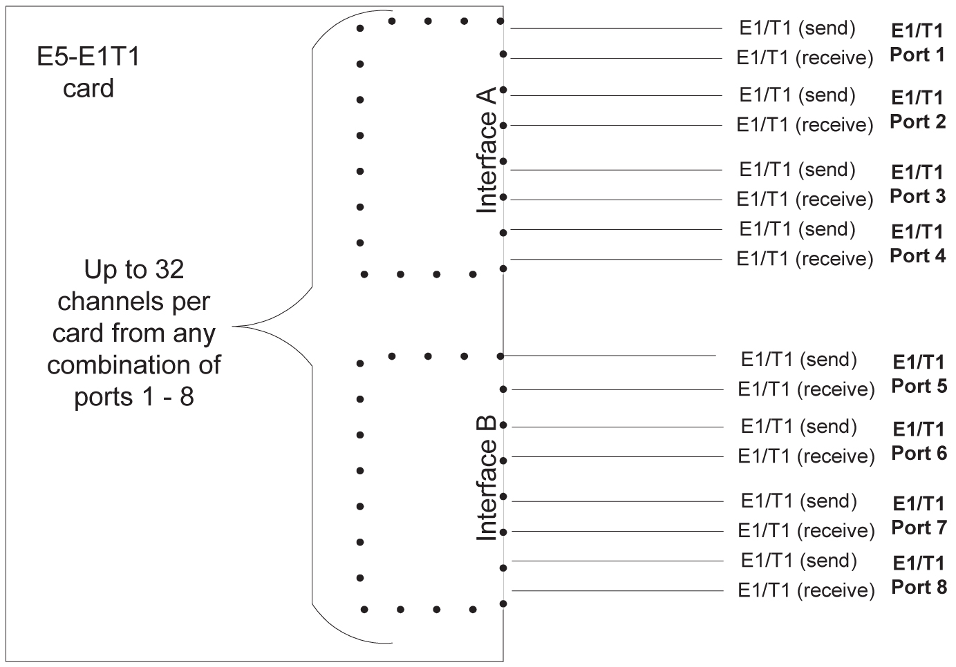
External interfaces (the E1/T1 trunks) use both backplane interfaces of the single backplane slot used, each terminating four E1/T1 ports (trunks). These two backplane interfaces will be referred to in this section as interfaces A and B. Interface A terminates E1/T1 ports 1-4, while Interface B terminates E1/T1 ports 5-8. Refer to Figure 3-35.
Figure 3-35 Channelized E5-E1T1-B Interfaces
Note:
All ports on a single board must operate in the same trunk format, E1 or T1, and that the total number of channels utilized as signaling links must not exceed the maximum allowable number in accordance with a Feature Access Key defining total channel capacity.Channel Bridging
Channel Bridging is the processing of signaling channels that are intermixed on trunks with voice or data channels. The HCMIM provides Channel Bridging which allows for better utilization of bandwidth without dedicating entire trunks to signaling. Non-signaling channels are bridged to an adjacent E1/T1 port for transport to other network devices. Likewise, signaling channels are merged to non-signaling data for transmission back to the mixed network.
In this configuration, the High-speed source Timing option can only apply to one trunk format since only one high-speed clock rate can be provided. Channel bridging is available only in the channelized mode. Refer to Figure 3-36.
Figure 3-36 Channel Bridging Schematic
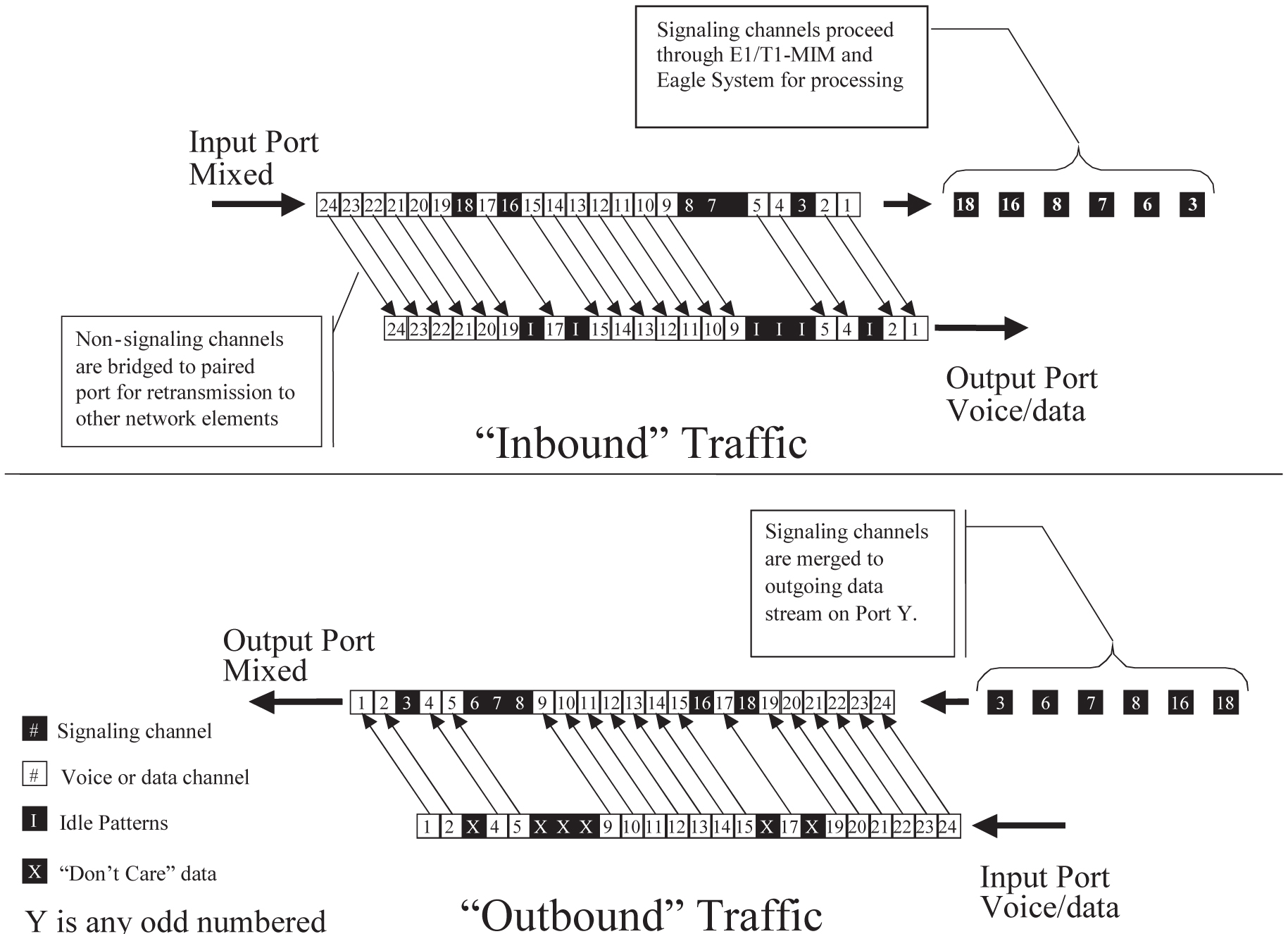
Time slots located on the bridging follower E1/T1 port, (time slots that have been dropped from the bridging source E1/T1 port), contain idle patterns provided by the EAGLE. All other idle time slots that are not dropped must contain an idle pattern provided by the remote network elements connected to both E1/T1 ports (bridging source and follower). Without these patterns on the idle time slots, instability of the E1/T1 may occur.
Note:
Provisioning of signaling links on the bridging follower E1/T1 port is not allowed while channel bridging is activated.Channel Bridging is implemented by pairing E1/T1 ports; this pairing limits provisioning to odd E1/T1 ports only (1,3,5,7) when channel bridging is enabled. The adjacent even numbered E1/T1 ports (2, 4, 6, 8) are used to allow the original non-signaling data received on the bridging source (odd) E1/T1 port to reach downstream network elements. This is a bi-directional interface so data is also able to enter the bridging follower E1/T1 port and leave through the bridging source E1/T1 port. This feature may be independently selected on E1/T1 ports 1, 3, 5, and/or 7. When selected, the bridging follower (even) E1/T1 port would be provisioned as the pass-through E1/T1 port. On ports operating in Channel Bridging mode, all time-slots not provisioned for signaling are handled as active data and not overwritten by the E5-E1T1.
Table 3-11 Channel Bridging E1/T1 Port Pairing
| PrimaryE1/T1 Port | PairedE1/T1 Port | ||
|---|---|---|---|
|
Number |
Payload Contents |
Number |
Payload Contents |
|
1 |
Signaling Processed |
2 |
Unprocessed |
|
3 |
Signaling Processed |
4 |
Unprocessed |
|
5 |
Signaling Processed |
6 |
Unprocessed |
|
7 |
Signaling Processed |
8 |
Unprocessed |
Timing
In order to use channel bridging without facility errors, both bridging source and bridging follower E1/T1 ports must be synchronous; that is, both source and follower must be timed off the same clock source. This synchronization may be accomplished two ways:
- The bridging source E1/T1 port may use the timing recovered from the bridging follower E1/T1 port or visa versa.
- Both the bridging source and bridging follower E1/T1 ports are using an external clock source (the EAGLE’s source option for the E1/T1 port provisioning).
Any other methods used for timing could cause problems on the E1/T1 trunk and are not supported.
Alarms and LEDs
The channel bridging functionality requires no additional statistics collection for the bridging follower E1/T1 port; however, standard statistics/measurements are made on the bridging source E1/T1 port. Alarms for the bridging follower E1/T1 port are limited to trunk-level synchronization and framing alarms. Channel alarm LEDs for the bridging follower E1/T1 port are amber to indicate the Channel Bridging mode of operation.
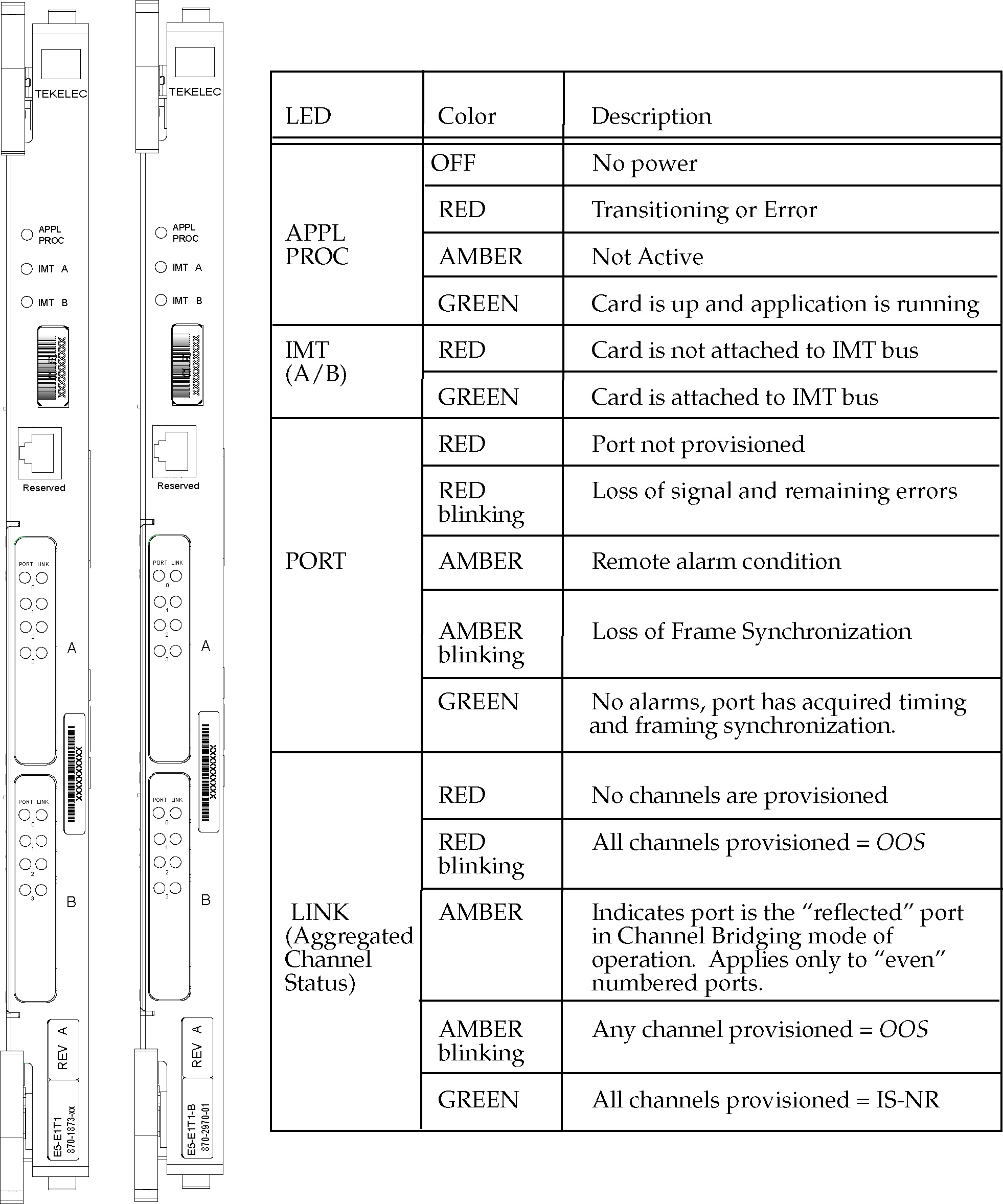
Three LEDs provide conventional EAGLE card indications of APPL Proc operation, and IMT A and IMT B operation. Up to sixteen (16) LEDs, two for each E1/T1 port, are used to indicate port and channel (signaling link) status. One LED per E1/T1 port indicates E1/T1 port Status and one LED per E1/T1 port indicates aggregated channel status. See Figure 3-37.
Figure 3-37 E5-E1T1-B
Technical Specifications
Table 3-12 E5-E1T1-B Technical Specifications
|
Power Requirements |
|
|
Voltage |
-48VDC |
|
Current |
0.67A |
|
Power |
32W |
|
Physical Characteristics |
|
|
Height |
14.43 in. (36.65 cm) |
|
Width |
1.013 in. (2.57 cm) |
|
Depth |
12.80 in. (32.51 cm) |
3.7.9 E5-ENET-B Module
Note:
Throughout this document, the term E5-ENET refers to the E5-ENET-B (P/N 870-2971-xx) card.- The E5-ENET has 2 physical 10/100 Mbps Ethernet ports.
- The E5-ENET supports STP Local Area Network function, and 10/100Base-T ethernet links to the STP.
- The
E5-ENET supports protocols as identified in
Table 3-13:
Note:
The E5-ENET is provisionable for IPLIMx or IPGWx, but does not support both functions on a single card simultaneously. - Requires HIPR2 to be active on both IMT buses in the shelf where the E5-ENET will reside.
- An adapter cable per Ethernet port. See Interface Cable Differences.
- Maximum number of cards per shelf is 10 for the control shelf and 16 for the extension shelf.
- Mix of E5-ENET/HCMIM on a shelf can be any up to shelf and power capacity.
- The E5-ENET does not require a fan tray assembly for thermal management.
- The E5-ENET-B requires the Message Flow Control (MFC) feature to be active.
- The E5-ENET-B does not support TVG.
- The E5-ENET-B requires a fan tray assembly for thermal management.
Table 3-13 E5-ENET-B Supported Protocols
| Feature | Protocols Supported |
|---|---|
|
IPSG |
M2PA, M3UA |
|
EROUTE |
TCP/IP |
Table 3-14 E5-ENET-B Capacities
| Parameter | IPGWY | |
|---|---|---|
|
E5-ENET-B cards per node |
250 |
|
|
SCTP entities perE5-ENET-B module |
50SCTP Connections |
|
|
The maximum possible EAGLE currently supports 4000 in the link table. |
||
Thermal Management
The E5-ENET-B includes thermal management and alarming provisions to protect the card from damage if environmental conditions hinder thermal stability. Table 3-15 identifies the appropriate responses.
When the CPU temperature rises above nominal range and exceeds a thermal threshold (Temperature Level1) a major alarm is raised against the card. When the temperature returns to its nominal range (below Temperature Level1) the alarm is automatically cleared.
- For IPGWx the link will be taken out of service and the far end will be notified that the connections will no longer accept traffic.
If the CPU temperature goes above operating limits (approximately 125ºC), the CPU will halt and the card will shut itself down to prevent permanent, catastrophic damage. In the event of thermal shutdown all processor activity will cease. If thermal shutdown occurs, the E5-ENET must then be reseated and allowed to load in order to clear the alarm and resume operation.
Table 3-15 Thermal Alarm Conditions
| Board Temperature | Actions |
|---|---|
|
Temp1 Exceeded |
Major alarm raised |
|
Temp2 Exceeded |
Critical alarm raised; failover initiated, traffic rerouted |
|
Temperature abated |
Normal operation restored |
|
Thermtrip - shutdown temperature exceeded |
CPU shuts down automatically.Card must be reseated to restore operation once temperature returns to normal operating conditions |
The thermal thresholds (Temperature Level1 and
Temperature Level2) are user configurable. The user configurable T1and T2
values will always be less than or equal to the T1 (max) and T2 (max) defined
for a particular board type respectively. See
Table 3-16
and the
chg-th-alm command for more details on
thermal thresholds.
Table 3-16 T1 and T2 temperature thresholds
| Cards | T1 Max (in Celsius) | T2 Max (in Celsius) | User Configurable T1 range (in %) | User Configurable T2 range (in %) |
|---|---|---|---|---|
| E5-ENET | 92 | 95 | (73-92)% of T2 max | (74-100)% of T2 max |
| E5-ENET-B | 83 | 90 | (73-92)% of T2 max | (74-100)% of T2 max |
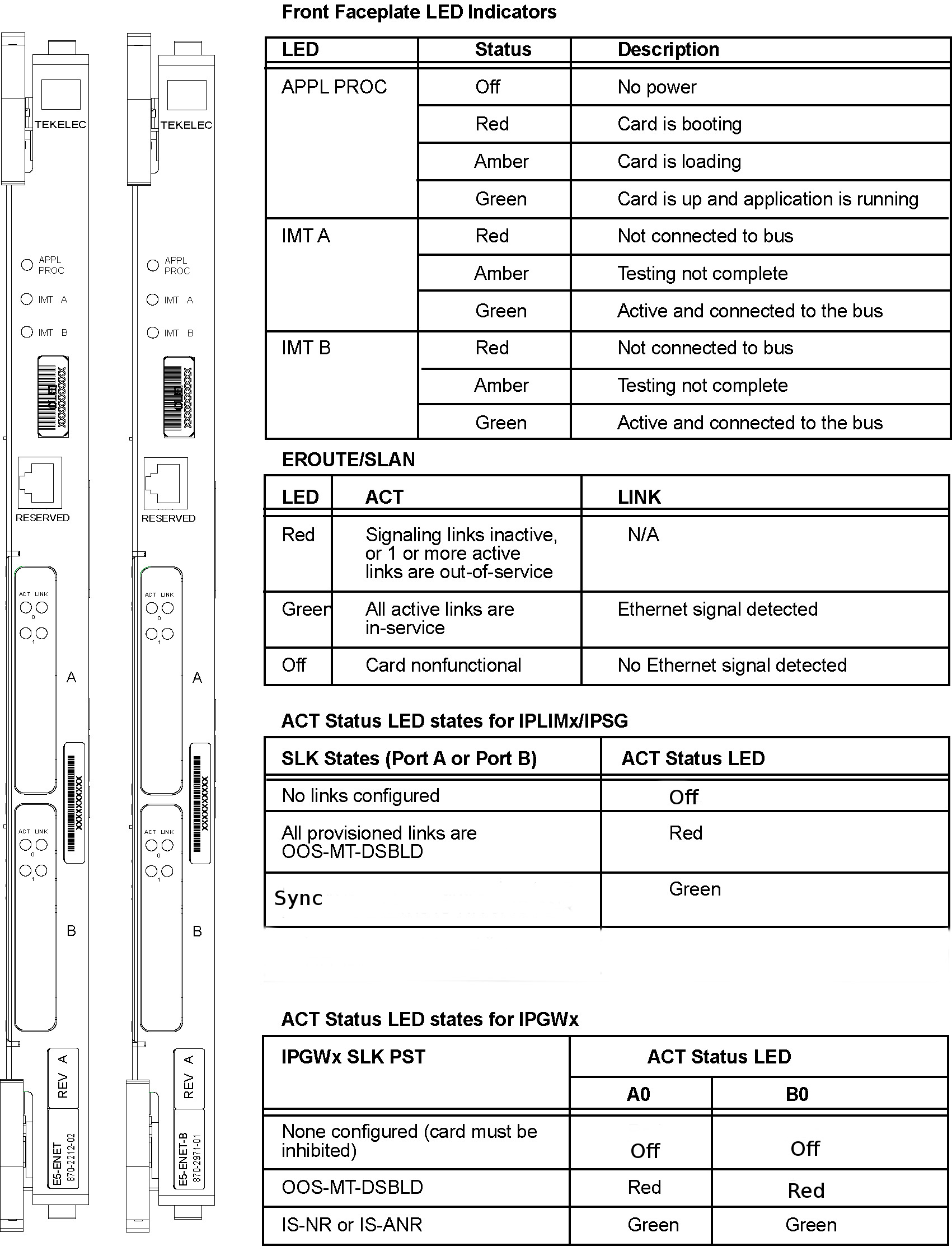
LED Indicators
The E5-ENET-B includes three front panel indicators (LEDs) for APPL Proc operation, IMT A, and IMT B status. In addition, eight front panel LED Link/Activity indicators (two for each IP port used).
Figure 3-38 E5-ENET-B
Interface Cable Differences
The PMC ports A0 and B0 are utilized as IP signaling link ports while PMC ports A1 and B1 support the Fast Copy feature when enabled. Each interface is independent of the others. The E5-ENET card and other DCM-class cards have backplane cable pinout differences requiring an adapter for the E5-ENET card. See Table 3-17.
The PMC ports A0 and B0 are utilized as IP signaling link ports while PMC ports A1 and B1 support the Fast Copy feature when enabled. Each interface is independent of the others. The E5-ENET card and other DCM-class cards have backplane cable pinout differences requiring an adapter for the E5-ENET card. See Table 3-18.
The Ethernet cable pinouts differ between the card and the DCM/SSEDCM cards.
- Adapter P/N 830-1103-02 is required for each E5-ENET interface used when using the existing DCM cable (P/N 830-0978-xx). The adapter is connected between the backplane connector and the existing DCM cable for the card.
- Adapter P/N 830-1102-02 is required for installation of the E5-ENET when the DCM cable is replaced with an RJ-45 CAT-5E cable (P/N 830-0724-xx). The adapter is connected to the backplane and the RJ-45 CAT-5E cable is connected from the other side of the adapter to a switch, or a hubcopy feature, or a patch panel (same place the DCM cable was terminated). This adapter configuration can be used for IPSG with the FAST COPY feature. When the adapter is connected (P1 to the backplane), the upper jack (P2) is for FAST COPY and the lower jack (P3) is the ethernet interface.
- Adapter P/N 830-1103-xx is required for each E5-ENET interface used when using the existing DCM cable (P/N 830-0978-xx). The adapter is connected between the backplane connector and the existing DCM cable for the card.
- Adapter P/N 830-1102-xx is required for installation of the E5-ENET when the DCM cable is replaced with an RJ-45 CAT-5E cable (P/N 830-0724-xx). The adapter is connected to the backplane and the RJ-45 CAT-5E cable is connected from the other side of the adapter to a switch, or a hubcopy feature, or a patch panel (same place the DCM cable was terminated). This adapter configuration can be used for IPSG with the FAST COPY feature. When the adapter is connected (P1 to the backplane), the upper jack (P2) is for FAST COPY and the lower jack (P3) is the ethernet interface.
- For IPSG with the FAST COPY feature, adapter P/N 830-1343-xx is required when
using existing cables (P/N 830-1204-xx) and additional CAT-5 shielded cables P/N
830-1174-xx for the monitoring ports are also required. When the adapter is
connected (P1 to the backplane), jack P2 is for FAST COPY and jack P3 is the
ethernet interface.
Table 3-17 Interface Cable/Adapter
Protocol Adapter Cable IPSG with FAST COPY
830-1102-02
830-0724-xx or 830-1174-xx
830-1343-01 (port A0, A1)
830-0978-xx or 830-1204-xx (backplane connector A)
830-1343-02 (port B0, B1)
830-0978-xx or 830-1204-xx (backplane connector B)
Table 3-18 Interface Cable/Adapter
Protocol Adapter Cable IPSG with FAST COPY
830-1102-xx
830-0724-xx or 830-1174-xx
830-1343-01 (port A0, A1)
830-0978-xx or 830-1204-xx (backplane connector A)
830-1343-02 (port B0, B1)
830-0978-xx or 830-1204-xx (backplane connector B)
If the card inserted into the slot does not match the backplane connector, the interface will not function.
Technical Specifications
Table 3-19 E5-ENET-B Technical Specifications
| Physical Characteristics | |
|---|---|
|
Height |
14.43 in. (36.65 cm) |
|
Width |
1.013 in. (2.57 cm) |
|
Depth |
12.80 in. (32.51 cm) |
3.7.10 SLIC
The Oracle Communications EAGLE Service and Link Interface Card (SLIC) is a single-slot, multi-use card that runs multiple applications. See "EAGLE Card Overview" in Release Notes for current GPL and Application compatibility. When provisioning the SLIC card, the card type will be SLIC when plugged in.
Thermal Management
The SLIC includes thermal management and alarming provisions to protect the card from damage if environmental conditions hinder thermal stability. In the event of thermal shutdown all processors activity ceases.
The SLIC requires a fan tray assembly for thermal management. Be sure to install the fan assembly before installing the SLIC card.
Thermal monitoring detects and provides notification of increasing card temperature, and disables the card when needed to prevent it from overheating.
- When the CPU temperature rises above nominal range and exceeds a thermal threshold (Temperature Level 1) a major alarm is raised against the card.
- If the temperature continues to increase and exceeds a second thermal threshold (Temperature Level 2), a critical alarm is raised against the card. When this second thermal event occurs, the application software auto-inhibits the card (refer to the table below).
- Once the temperature recedes under the Temperature Level 2 threshold, the application re-allows operation and sets its state to IS-NR/Idle. The raised critical alarm is cleared and the corresponding major alarm is raised.
- When the temperature returns to its nominal range (below Temperature Level 1) the raised major alarm is cleared.
Note:
These thermal thresholds (Temperature Level 1 and Temperature Level 2) are user configurable. For more information refer to thechg-th-alm command in
Commands User's Guide.
Table 3-20 Thermal Alarm Conditions
| Board Temperature | SLIC Actions |
|---|---|
|
Temp Level 1 Exceeded |
Major alarm raised |
|
Temp Level 2 Exceeded |
Critical alarm raised; Auto-inhibit is allowed by the user on that card and set their status to OOS-MT-DSBLD/MEA. Set card state to out-of-service, maintenance fault. |
|
Temperature abated |
When temperature drops below Temperature Level 2, Temperature Level 1 action/state restored. When the temperature drops below Temperature Level 1, normal operation restored. |
|
Thermtrip - shutdown temperature exceeded |
CPU shuts down automatically.Card must be reseated to restore operation once temperature returns to normal operating conditions |
Alarms and LEDs
The SLIC has 21 LEDs visible on the faceplate. The LEDs are visible with the aid of a light pipe, which directs the light from the LED to the front panel.
Figure 3-39 SLIC
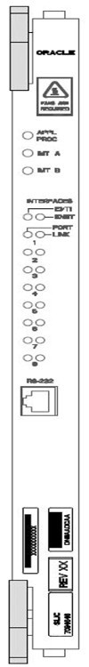
Table 3-21 SLIC Front Panel LEDs
| LED Name | Control | Colors | Definition |
|---|---|---|---|
| APPL | FPGA / Application Software | Off / Red / Green |
Off - No power Red - Card is booting Green - Card is running Application |
| IMTA | LIIC FPGA / Communication Software | Red / Green |
Red -Not connected to BUS Green - Active and Connected to Bus Amber - MUX card on the same shelf is seated and not inhibited; bus not available |
| IMTB | LIIC FPGA / Communication Software | Red / Green |
Red - Not connected to BUS Green - Active and Connected to Bus Amber - MUX card on the same shelf is seated and not inhibited; bus not available |
| INTERFACES E1/T1 | FPGA / Application Software | Green / Off |
Green - Enabled Off - Disabled |
| INTERFACES ENET | FPGA / Application Software | Green / Off |
Green - Enabled Off - Disabled |
| PORT1-PORT8 | PHY / Application Software | Off / Red / Green |
Off - Not configured Red - Cable removed and/or not synced Green - 10/100Mb link speed |
| LINK1-LINK8 | FPGA / Application Software | Off / Red / Green |
Off - No SLKS configured Red - All Configured SLKS OOS Green - All SLKS aligned |
3.7.11 E5-MCPM-B Module
The single-slot E5-MCPM-B (P/N 870-3089-xx) card can be used for nodes larger than 1200 (if 15 Measurements is enabled). E5-OAM Integrated Measurements can still be used for smaller nodes.
E5-MCPM-B modules require a fan tray assembly for thermal management. Be sure to install the fan assembly before installing the E5-MCPM-B card. See "Hardware Baseline Table" in Release Notes for compatible fan assembly part numbers.
Note:
The E5-MCPM-B card is a requirement for the FTP measurements feature. The FTP measurements feature uses the E5-MCPM-B ethernet ports to transfer measurements information directly to a FTP server.Thermal Management
The E5-MCPM-B includes thermal management and alarming provisions to protect the card from damage if environmental conditions hinder thermal stability.
When the CPU temperature rises above nominal range and exceeds a thermal threshold (Temperature Level1) a major alarm is raised against the card. When the temperature returns to its nominal range (below Temperature Level1) the alarm is automatically cleared.
If the temperature continues to increase and exceeds a second thermal threshold (Temperature Level2) a critical alarm is raised against the card. When this second thermal event occurs, the result is a local processor outage (LPO) and critical thermal alarm on the primary MCP will initiate a role change arbitration with the secondary MCP, which may or may not result in a role change. The state of card will transition to ‘in-service abnormal’ state. If the temperature recedes under the Temperature Level2 threshold, the LPO condition is cleared and the card can begin operation again.
If the CPU temperature goes above operating limits (approximately 99ºC), the CPU will halt and the card will shut itself down to prevent permanent, catastrophic damage. In the event of thermal shutdown all processor activity will cease. If thermal shutdown occurs, the E5-MCPM-B must then be reseated and allowed to load in order to clear the alarm and resume operation.
Table 3-22 identifies the appropriate responses.
Table 3-22 Thermal Alarm Conditions
| Board Temperature | Actions |
|---|---|
|
Temp1 Exceeded |
Major alarm raised |
|
Temp2 Exceeded |
Critical alarm raised; If the card is the primary MCP, a role change will be initiated. Card state transitions to IS-ANR. |
|
Temperature abated |
Normal operation restored |
|
Thermtrip - shutdown temperature exceeded |
CPU shuts down automatically. Card must be reseated to restore operation once temperature returns to normal operating conditions |
The thermal thresholds (Temperature Level1 and Temperature Level2) are user configurable. The user configurable T1and T2 values will always be less than or equal to the T1 (max) and T2 (max) defined for a particular board type respectively. See Table 3-23 and the chg-th-alm command for more details on thermal thresholds.
Table 3-23 T1 and T2 temperature thresholds
| Cards | T1 Max (in Celsius) | T2 Max (in Celsius) | User Configurable T1 range (in %) | User Configurable T2 range (in %) |
|---|---|---|---|---|
| E5-MCPM-B | 83 | 90 | (73-92)% of T2 max | (74-100)% of T2 max |
Alarms and LEDs
The E5-MCPM-B includes three front panel indicators (LEDs) for APPL Proc operation, IMT A, and IMT B status. In addition, four front panel LED Act/Link indicators (two for each IP port used). The Link indicator will illuminate Green when the interface is connected to an active Ethernet device and is Off when not connected. The Activity indicator will be Green when the IP signaling links are active and synchronized and RED otherwise.
Figure 3-40 E5-MCPM-B
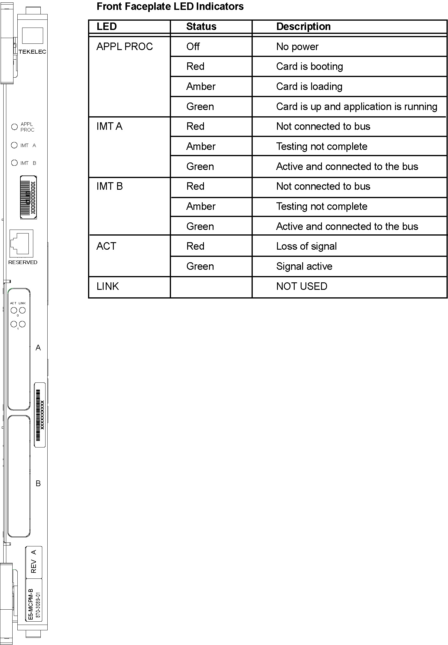
Technical Specifications
Table 3-24 E5-MCPM-B Technical Specifications
| Physical Characteristics | |
|---|---|
|
Height |
14.43 in. (36.65 cm) |
|
Width |
1.013 in. (2.57 cm) |
|
Depth |
12.80 in. (32.51 cm) |
3.7.12 E5-SM8G-B Module
Note:
All E5-based cards require HIPR2. For more information, see High-Speed IMT Packet Router 2.- Support for the VSCCP features
- SS7 traffic exchange between B,C,D links and the IP network
- Support for the 150K TPS GTT and 75K TPS G-Port features
- Enhanced bulk download
- Requires HIPR2 to be active on both IMT buses in the shelf where the E5-SM8G-B will reside.
- Requires the Message Flow Control (MFC) feature to be active.
- Requires a fan tray assembly for thermal management.
- The E5-SM8G-B is restricted from accessing the IMT bus through hardware control.
- Can replace a DSM in the control or extension frame without requiring additional provisioning.
- Can interoperate with DSMs at an operating capacity of 850, 1100, or 1700 transactions per second (TPS).
- Can also interoperate with two channel LIM cards per node. The E5-SM8G-B provides two physical 10/100/1000 Mbps Ethernet ports.
Thermal Management
The E5-SM8G provides thermal management and alarming provisions to protect the card from damage due to overheating. The E5 SM8G contains a thermal monitor with software selectable thresholds for temperature abnormal levels. Threshold crossings generate alarms accompanied by application processor interrupts. These interrupts require the mitigation of the temperature rise to resume normal card operations interrupted by the threshold crossings. The E5-SM8G is designed to operate in the EAGLE shelf with natural convection cooling and does not require a fan tray for cooling.
When the CPU temperature rises above nominal range and exceeds a thermal threshold, a major alarm is raised against the card. When the temperature returns to its nominal range the alarm is automatically cleared.
If the temperature continues to increase and exceeds a second thermal threshold, a critical alarm is raised against the card. When this second thermal event occurs, the result is a local processor outage (LPO) and outstanding grant requests shall be completed but no new grant requests shall be accepted, an LPO will take the card out-of-service. If the temperature recedes under the threshold, the LPO condition is cleared and the card can begin operation again.
If the CPU temperature goes above operating limits (approximately 125ºC), the CPU will halt and the card will shut itself down to prevent permanent, catastrophic damage. In the event of thermal shutdown all processor activity will cease. If thermal shutdown occurs, the E5-SM4G must then be reseated and allowed to load in order to clear the alarm and resume operation.
Table 3-25 Thermal Alarm Conditions
| Board Temperature | E5-SM8G Actions |
|---|---|
|
Temp Level 1 Exceeded |
Major alarm raised |
|
Temp Level 2 Exceeded |
Critical alarm raised; outstanding grant requests shall be completed but no new grant requests shall be accepted; card state set to out-of-service, maintenance fault. |
|
Temperature abated |
Normal operation restored. |
|
Thermtrip - shutdown temperature exceeded |
CPU shuts down automatically.Card must be reseated to restore operation once temperature returns to normal operating conditions |
The thermal thresholds (Temperature Level1 and
Temperature Level2) are user configurable. The user configurable T1and T2
values will always be less than or equal to the T1 (max) and T2 (max) defined
for a particular board type respectively. See
Table 3-26
and the
chg-th-alm command for more details on
thermal thresholds.
Table 3-26 T1 and T2 temperature thresholds
| Cards | T1 Max (in Celsius) | T2 Max (in Celsius) | User Configurable T1 range (in %) | User Configurable T2 range (in %) |
|---|---|---|---|---|
| E5-SM4G | 92 | 95 | (73-92)% of T2 max | (74-100)% of T2 max |
| E5-SM8G-B | 83 | 90 | (73-92)% of T2 max | (74-100)% of T2 max |
Alarms and LEDs
Three LEDs provide conventional EAGLE card indications of APPL Proc operation, and IMT A and IMT B operation. Four (4) LEDs, two for each port, are used to indicate port and signaling link status.
Table 3-27 Front Faceplate LED Indicators
| LED | PORT | ACT |
|---|---|---|
|
RED |
No signal detected |
|
|
GREEN |
Data link active operating at 10/100 Mbps |
Signal detected |
|
AMBER |
Data link active operating at 1 Gbps |
|
|
OFF |
Card non-functional |
Card non-functional |
Figure 3-41 E5-SM8G-B LED Indicators
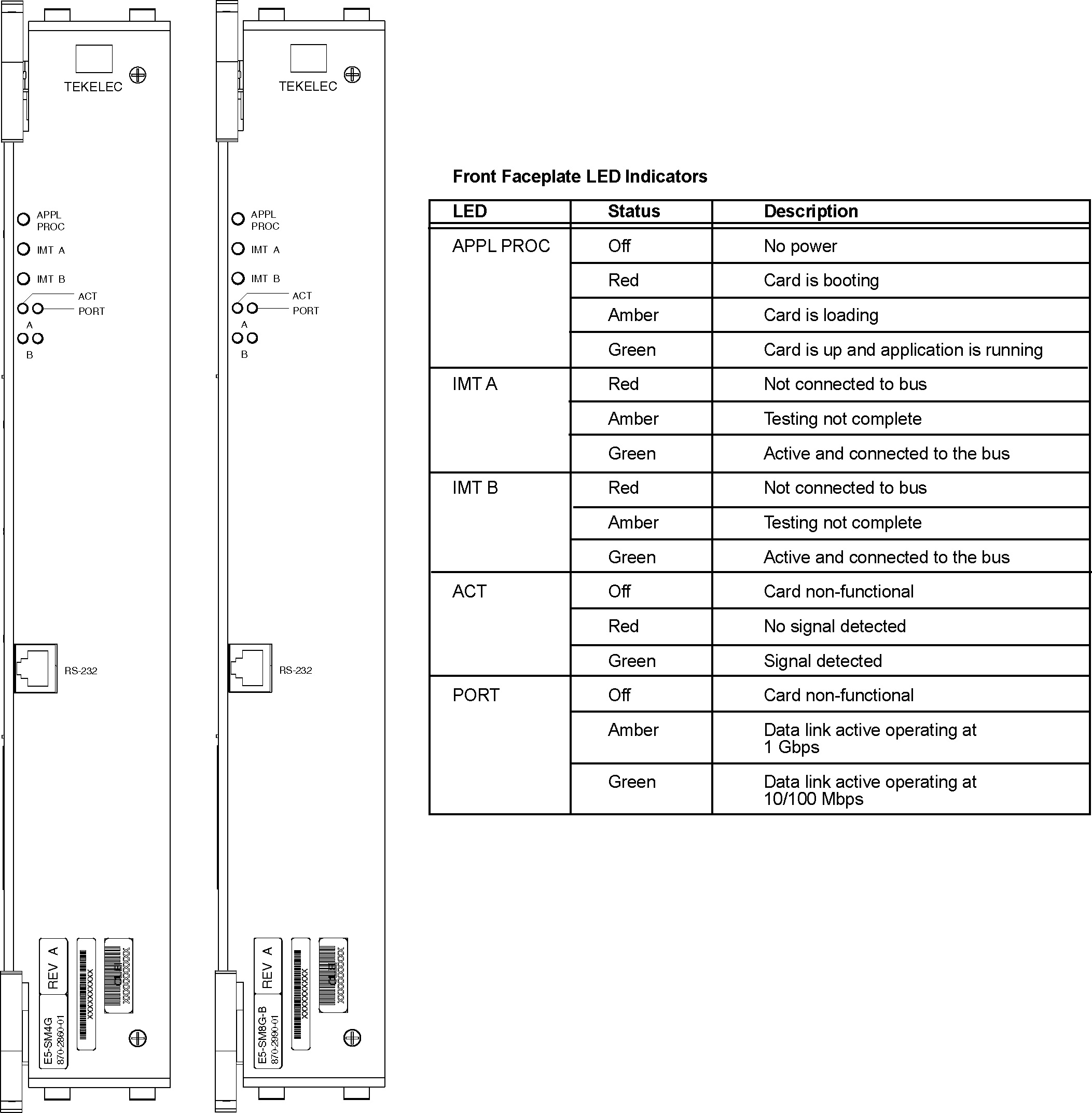
Interface Cable Adapter
An adapter, P/N 830-1104-03, and a CAT 5E cable may be used in place of the existing DCM cable. The adapter is connected to the backplane and the RJ-45 CAT 5E cable is connected from the other side of the adapter to a switch, or a hub, or a patch panel (same place the DCM cable was terminated).
An adapter, P/N 830-1104-xx, and a CAT 5E cable may be used in place of the existing DCM cable. The adapter is connected to the backplane and the RJ-45 CAT 5E cable is connected from the other side of the adapter to a switch, or a hub, or a patch panel (same place the DCM cable was terminated).
Technical Specifications
Table 3-28 E5-SM8G-B Technical Specifications
| Physical Characteristics | ||
|---|---|---|
|
Height |
14.43 in. (36.65 cm) |
|
|
Width |
2.06 in. (5.23 cm) |
|
|
Depth |
12.80 in. (32.51 cm) |
|
3.7.13 Air Management Card
The Air Management (P/N 870-1824-02) card is an unpowered filler card used to ensure efficient air flow in shelves equipped with fans. Air Management cards are required in all empty slots in the shelf immediately above the fan assembly.
Note:
See "Hardware Baseline Table" in Release Notes for compatible fan assembly part numbers.Figure 3-42 Air Management card
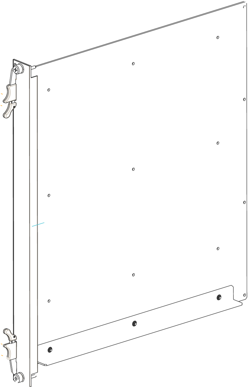
3.7.14 Fan Tray
The EAGLE fan tray contains three -48V fans that provide a redundant airflow for thermal management of the shelf. The EAGLE fan tray is powered by –48 VDC, at a fused rating of 3A. It has redundant power inputs (A and B). Each input is provided by a DB-9, keyed, positive locking connector. The contacts have 30 micro-inches of gold plating.
Note:
Shelves with HCMIM, E5-ENET-B, E5-ATM-B, E5-MCPM-B, E5-SM8G-B or SLIC cards are required to be cooled by a fan tray.Note:
See "Hardware Baseline Table" in Release Notes for compatible fan tray part numbers.Figure 3-43 Fan Tray
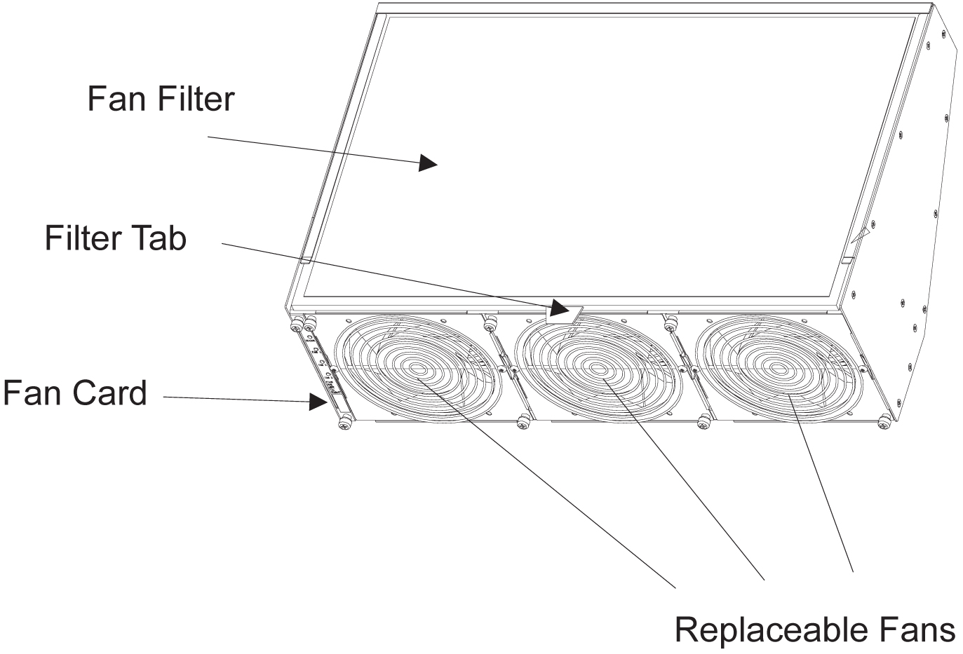
Failover is governed by a fan controller card on the fan tray. The fan tray will provide adequate airflow if there is a single fan failure or during replacement of one of the three fans while the EAGLE fan tray is operational. The control card bracket provides mounting for the control PCB (P/N 850-0703-01). The control PCB inserts into the front face of the fan tray on card guides mounted to the left side wall, and is intended to be a field replaceable item.
The EAGLE fan tray is designed to be field installable, with mounting brackets, in both a Heavy Duty frame and a standard frame. There is one disposable air filter in the assembly (P/N 551-0032-01). The filters should be changed once a month.
The EAGLE fan tray is designed to be compliant to Bellcore Standards GR-63-CORE, GR-78-CORE, and GR-1089-CORE when mounted in a Heavy Duty Frame or standard frame. The EAGLE fan tray is also designed to be UL and CE compliant. The EAGLE fan tray is designed to operate in a Central Office environment with continuous operation at -5C to 50C and 5% to 90% RH in compliance with GR-63-CORE.
3.8 Fuse and Alarm Panels
The Fuse and Alarm Panel (FAP) provides protected distribution of –48VDC power to the shelves in the frame. The site voltage input to each frame should be between -40VDC and -57.5VDC. Allowing for the full population of a frame and for the failure of one primary supply, new installations of Control and Extension frames require two 60A feeds. See the "Hardware Power Calculator Tool" section in Hardware for more information.
The FAP is installed at the top of the frame and uses two cables to bring A and B power to the frame. The FAP contains two separate circuits, A and B. Current flows from the input terminals to the fuse bus. Protection is provided by fuses placed in fuse holders on the front panel. When a fuse is installed in a fuse holder, the circuit is completed to the output connector.
warning:
Existing frames that are fused at 40 amps may be upgraded to support 60 amps with a FAP upgrade kit. Frames that contain HC-MIMs must be upgraded to support 60 amps. Customers do not perform a FAP upgrade; these upgrades are performed by Oracle Communications personnel.warning:
The FAP P/N 870-1606-02 Revs A-B can be upgraded to FAP P/N 870-1606-02 Rev C with FAP upgrade kit P/N 840-0139-01. The FAP P/N 870-2320-01 Revs A-I can be upgraded to FAP P/N 870-2320-01 Rev J with FAP upgrade kit P/N 870-0139-02.Caution:
All personnel associated with the installation of this system must adhere to all safety precautions and protection equipment required to avoid the possibility of injury to personnel, service degradation, and/or service interruption.Caution:
This is a redundant system to allow service during normal maintenance. When repairs require a total power disconnect, both input supply sources must be disconnected. This will cause service interruption and take down the system.3.8.1 Fuses
The fuse and alarm panel uses GMT-type fuses of different amperage ratings for individual circuit protection. If a frame circuit fuse is blown the alarm is indicated by an LED on the front panel and a small colored flag on the fuse shows the fuse that has failed (refer to Figure 3-44. Refer to Maintenance for procedures on replacing fuses and the FAP assembly.
Caution:
Always use a fuse of the same type and amperage rating when replacing a failed fuse.Figure 3-44 Fuse (GMT Brand Shown)
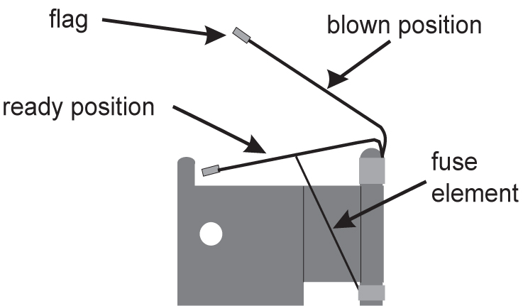
Table 3-29 Fuse Color Codes of Alarm Flags
| Fuse Amp | Fuse Flag Color | Fuse Amp | Fuse Flag Color | |
|---|---|---|---|---|
|
0.18A |
Orange-Red |
2A |
Orange |
|
|
0.2A |
Black-Red |
2.5A |
White-Orange |
|
|
0.25A |
Violet |
3A |
Blue |
|
|
0.33A |
Yellow-Green |
3.5A |
White-Blue |
|
|
0.375A |
White-Green |
4A |
White -Brown |
|
|
0.5A |
Red |
5A |
Green |
|
|
0.65A |
Black |
7.5A |
Black-White |
|
|
0.75A |
Brown |
10A |
Red-White |
|
|
1A |
Gray |
12A |
Yellow-Green |
|
|
1.33A |
White |
15A |
Red-Blue |
|
|
1.5A |
White-Yellow |
3.8.2 Fuse and Alarm Panel (P/N 870-2804-01)
The FAP (P/N 870-2804-01) is a low-profile (1U) unit that can be installed in the Control Frame (CF) and the Extension Frame (EF).
The Power Alarm LED indicates the input power state to the FAP. The LED is green when input power is applied to that bus of the FAP and is red when there is no input power to that bus of the FAP. An unlit Power Alarm LED indicates a failed LED or no input power to either bus of the FAP.
Alarm LEDs to indicate Critical, Major, and Minor alarms are located to the left of the diode board. The LEDs indicate alarms generated by the system that are applicable to that frame which the FAP is installed.
The FAP contains a Diode board and a Shorting board. These boards are located at the front center of the FAP. The FAP also contains two fuse blocks, one to the left (A-side) and one to the right (B-side) of diode and shorting boards, consisting of 20 fuse positions each. The Fuse Alarm LED indicates the failure of a fuse.
The diode board in the FAP contains power diodes and circuitry which allow one bus to pick up the entire load when there is a loss of input power on the other bus.
The Shorting board allows the removal of the diode board without taking down the system. This permits periodic maintenance of the diodes without having to power down or remove the unit from the shelf. For maintenance operation, the Shorting board has to be removed, flipped over, and reinstalled. In the bypass position, both A and B power is connected to the fuse blocks so the diode board can be safely removed. The Shorting board has an LED which is off when the board is in normal operational mode and is green when in the bypass mode of operation. With the Shorting board in the bypass mode, the OR’ing function is not available. Refer to Maintenance for additional information to place the FAP into Maintenance Mode of operation.
Figure 3-45 and Table 3-30 describes the front panel configuration of the fuse and alarm panel (P/N 870-2804-01).
Figure 3-45 Fuse and Alarm Panel - Front View (P/N 870-2804-xx)
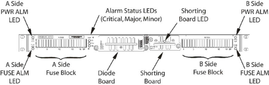
Table 3-30 Fuse and Alarm Panel Front Items (P/N 870-2804-xx)
| Fuse Panel Item | Description |
|---|---|
|
Fuse Positions |
Two groups of 20 GMT fuses |
|
Shorting Board LED |
LED indicator for shorting board. |
|
FuseAlarm |
LED indicator for fuse fail alarm |
|
PowerAlarm |
LED indicator for input power |
|
CriticalAlarm |
LED indicator for critical alarm |
|
MajorAlarm |
LED indicator for major alarm |
|
MinorAlarm |
LED indicator for minor alarm |
Table 3-31 presents possible alarm LED states and corresponding fuse conditions.
Table 3-31 Fuse State and LED condition (P/N 870-2804-01).
| Fuse State A side | Fuse State B side | Fuse LEDs A side | Fuse LEDs B side |
|---|---|---|---|
|
No fuses blown |
No fuses blown |
Green |
Green |
|
No fuses blown |
At least 1 fuse blown |
Green |
Red |
|
At least 1 fuse blown |
No fuses blown |
Red |
Green |
|
At least 1 fuse blown |
At least 1 fuse blown |
Red |
Red |
|
Shorting board enabled (in bypass mode), Shorting board LED is green. |
Red |
Red |
|
|
Shorting board in normal operational mode, Shorting board LED is off. No fuses blown. |
Green |
Green |
Figure 3-46 and Table 3-32 describes the rear panel configuration. Refer to Installation for cabling connection information.
Figure 3-46 Fuse and Alarm Panel Rear (P/N870-2804-01).
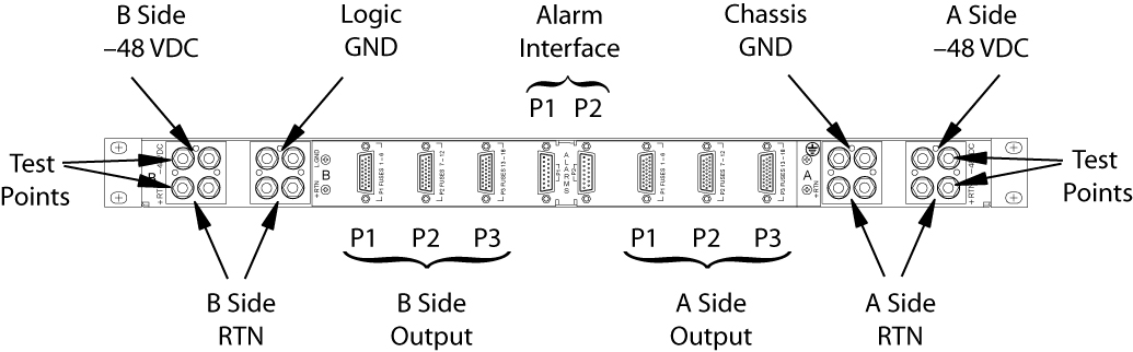
Table 3-32 Fuse and Alarm Panel Rear Items (P/N870-2804-01).
| Fuse Panel Item | Description |
|---|---|
|
Input Terminal Block A |
Input and Return for power source A and FAP Chassis Ground |
|
Input Terminal Block B |
Input and Return for power source B and FAP Logic Ground |
|
–48VDC Outputs A |
26-pin “D” connectors for A-side outputs:
|
|
–48VDC Outputs B |
26-pin “D” connectors for B-side outputs:
|
|
Alarm Interface |
15-pin “D” connectors:
|
Table 3-33 presents the power requirements and physical dimensions for the FAP.
Table 3-33 Fuse and Alarm Panel Specifications (P/N 870-2804-01).
| Dimensions | |
|---|---|
|
Height Width Depth |
1.75 inches (4.4 cm) 21.5 inches (53.8 cm) 10 inches (25 cm) |
3.8.3 Fuse and Alarm Panel (P/N 870-1606-xx/870-2320-xx)
The FAP P/N 870-1606-xx can be installed in standard frames. The FAP P/N 870-2320-xx can be installed in heavy duty frames.
The FAP contains an alarm board, two diode boards, and a jumper board. These boards are located at the front center of the FAP. The fuse holders are to the left and right of these boards as shown in Figure 3-47.
The alarm board contains a FUSELED to indicate a failed fuse (for either bus A or B) and LEDs to indicate Critical, Major, and Minor alarms generated by the system that are applicable to that frame which the FAP is installed.
There are two diode boards in the FAP, one for bus A and one for bus B. Each diode board contains power diodes and circuitry which allow one bus to pick up the entire load when there is a loss of input power on the other bus. An LED indicates the input power state to the FAP. The LED is green when input power is applied to that bus of the FAP and is red when there is no input power to that bus of the FAP.
The Maintenance (Jumper) board allows the removal of one or both diode boards without taking down the system. The Jumper board has two connectors and a connector plug. During normal operation, the connector plug is seated on the first connector. For maintenance operation, the jumper board has to be removed and the connector plug moved to the second connector. In the maintenance position, the connector plug connects both A and B power feeds to the fuse panels so one or both diode boards can be safely removed. The OP/MAINTLED is green when the Jumper board is in normal operational mode and is red when in the maintenance mode of operation. Refer to Maintenance.Figure 3-47 and Table 3-34 describes the front panel configuration of the fuse and alarm panel (P/N 870-1606-xx/870-2320-xx).
Figure 3-47 Fuse and Alarm Panel (P/N 870-1606-xx/870-2320-xx) Front
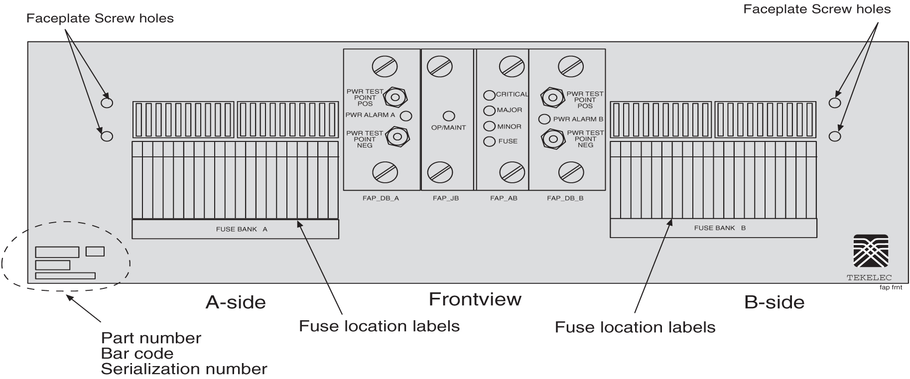
Table 3-34 Fuse and Alarm Panel Front Items
|
Fuse Panel Item |
Description |
|
Fuse Positions |
Two groups of 20 GMT fuses |
|
PWR ALARM |
LED indicator for A or B diode board input power
|
|
OP/MAINT |
LED indicator for mode of operation
|
|
FUSE |
LED indicator for fuse fail alarm
|
|
CRITICAL |
LED indicator for frame critical alarm |
|
MAJOR |
LED indicator for frame major alarm |
|
MINOR |
LED indicator for frame minor alarm |
Figure 3-48 and Table 3-35 describes the rear panel configuration of fuse and alarm panel (P/N 870-1606-xx). Refer to Installation for cabling connection information.
Figure 3-48 Fuse and Alarm Panel (P/N 870-1606-xx/870-2320-xx) Rear
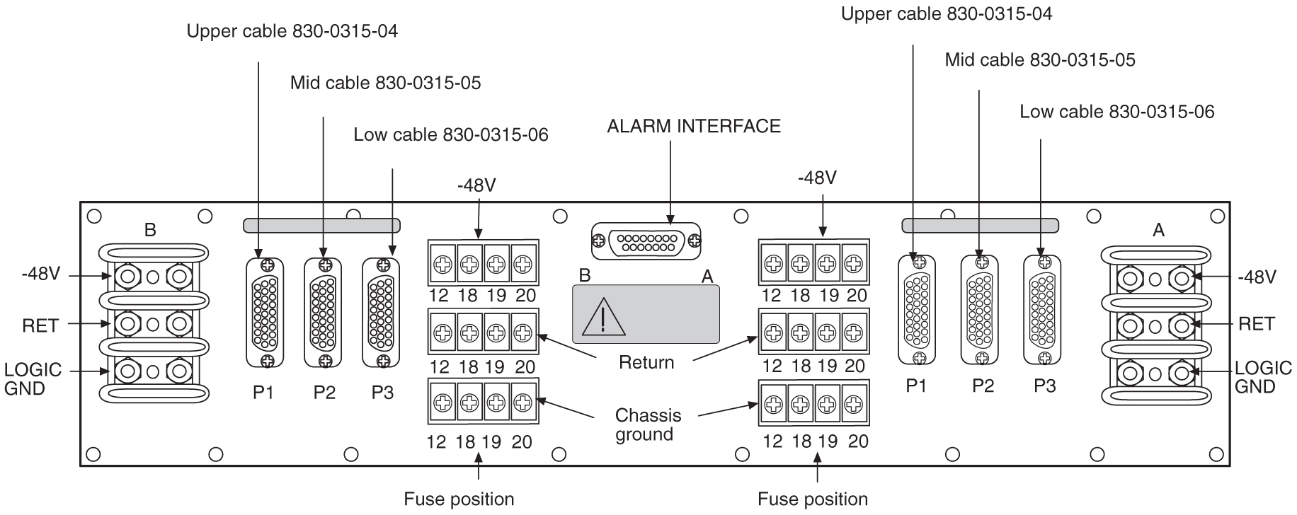
Table 3-35 Fuse and Alarm Panel (P/N 870-1606-xx/870-2320-xx) Rear
| Fuse Panel Item | Description |
|---|---|
|
Input Terminal Block A |
Logic Ground, Return, and Input for power source A |
|
Input Terminal Block B |
Logic Ground, Return, and Input for power source B |
|
Output Terminal Block A |
–48VDC, Chassis Ground, and RTN for Fuse location 12, 18, 19, and 20 for side A. These are miscellaneous extra capacity fuses refer to Provision Rules for FAP Fuse Locations . |
|
Output Terminal Block B |
–48VDC, Chassis Ground, and RTN for Fuse location 12, 18, 19, and 20 for side B. These are miscellaneous extra capacity fuses refer to Provision Rules for FAP Fuse Locations |
|
–48VDC, Chassis Ground, and RTN Outputs A |
26-pin “D” connectors, P1, P2, and P3 for A-side outputs. |
|
–48VDC, Chassis Ground, and RTN Outputs B |
26-pin “D” connectors, P1, P2, and P3 for B-side outputs. |
Table 3-36 Fuse and Alarm Panel (P/N 870-1606-xx/870-2320-xx) Specifications
| Dimensions | |
|---|---|
|
Height Width Depth |
3 inches (7.6 cm) 17 inches (43.2 cm) 10.25 inches (26 cm) |
3.8.4 Provision Rules for FAP Fuse Locations
The following are provisioning rules for fuse placement apply to FAP P/N870-2804-xx:
-
Maximum fuse size 3 amp.
-
Fuse positions 19 and 20 not used.
-
Power feed must originate from the same power source.
-
Fuse and Alarm Panel Shorting board in bypass mode must be less than 40 amp per distributed output side.
These provisioning rules for fuse placement apply to FAPs P/N 870-1606-xx and P/N 870-2320-xx.
-
Maximum fuse size 3 amp for Fuse one through Fuse 18 when P1, P2, or P3 are used for power output
-
P2 cannot be used if the Terminal Strip (output) position 12 is used.
-
P3 cannot be used if the Terminal Strip (output) position 18 is used.
-
Fuse maximum of 15 amp for fuse positions 12, 18, 19, and 20, all other fuse positions are 3 amp.
Note:
For fuse locations 12, 18, 19, and 20, the fuse maximum is 10 amp when adjacent locations are used. -
Power feed must originate from the same power source.
-
Fuse and Alarm Panel, Jumper Board (P/N 870-1641-01) fuse size on boards 40 amp per side for P/N 870-1606-02 Rev A and B, and for P/N 870-2320-01 Rev A through I. Fuse size on boards 60 amp per side for P/N 870-1606-02 Rev C and 870-2320-01 Rev J.
-
Fuse and Alarm Panel, Jumper board in maintenance mode must be less than 40 amp per distributed output side.
3.9 Holdover Clock
Figure 3-49 Holdover Clock, Card Location
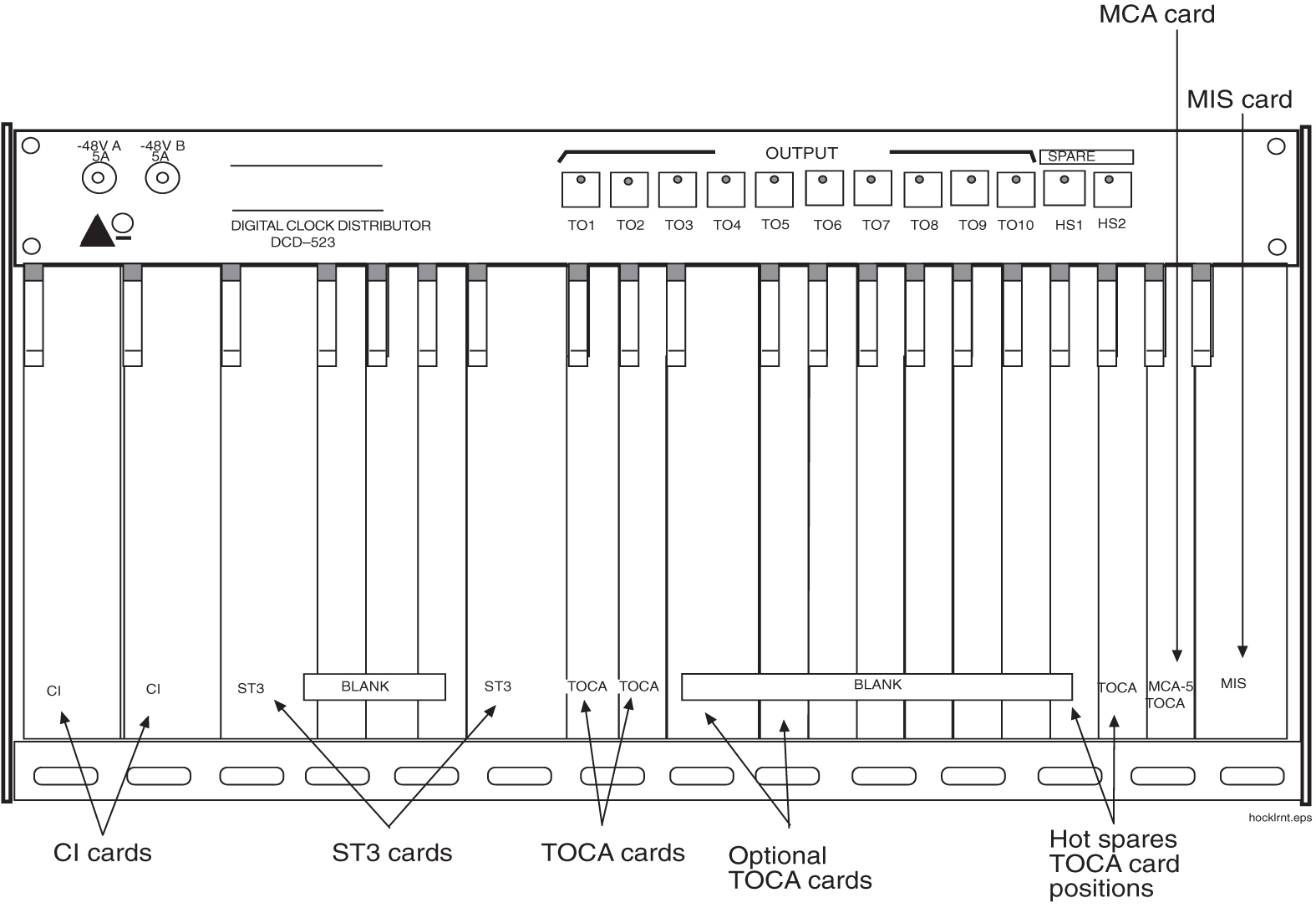
Figure 3-50 Holdover Clock, Frame Connections
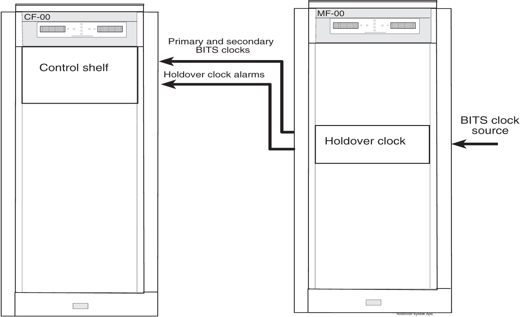
Maintenance Interface System Card
The Maintenance Interface System (MIS)(P/N 804-0175-01) card provides local and remote command and control for the holdover clock. The MIS card is installed in the far right slot of the holdover clock shelf (refer to Figure 3-51 for an MIS card block diagram).
The MIS provides Data Carrier Detect (DCD) alarm summary with office and remote alarm relay closures and status indicators, as well as remote RS-232 communication.
Output alarms from the Timing Output Composite Clock Automatic (TOCA) cards, input reference alarms from the clock inputs, and failure alarms from any card in the shelf are sent to the MIS card. Status indications including clock loss and port alarms are also monitored by the MIS card.
Depending on which alarms are received, the MIS activates audible and visual alarm and Status Indicator (SI) outputs. An additional set of status leads on the back enables either a major, minor, or critical alarm in the event of the failure of a battery or blown fuse.
Note:
Major, minor, and critical alarm leads have both Normally Open (NO) and Normally Closed (NC) dry relay contacts. Major, minor, and critical status indicators have NO relay contacts only. All other Status Indicators are open-collector outputs between the SI lead and battery return.Alarm battery supply is not required for the system. When DC power is lost to the shelf, the normally open relays close, initiating an office alarm (refer to Figure 3-51).
Figure 3-51 Maintenance Interface System Card Block Diagram
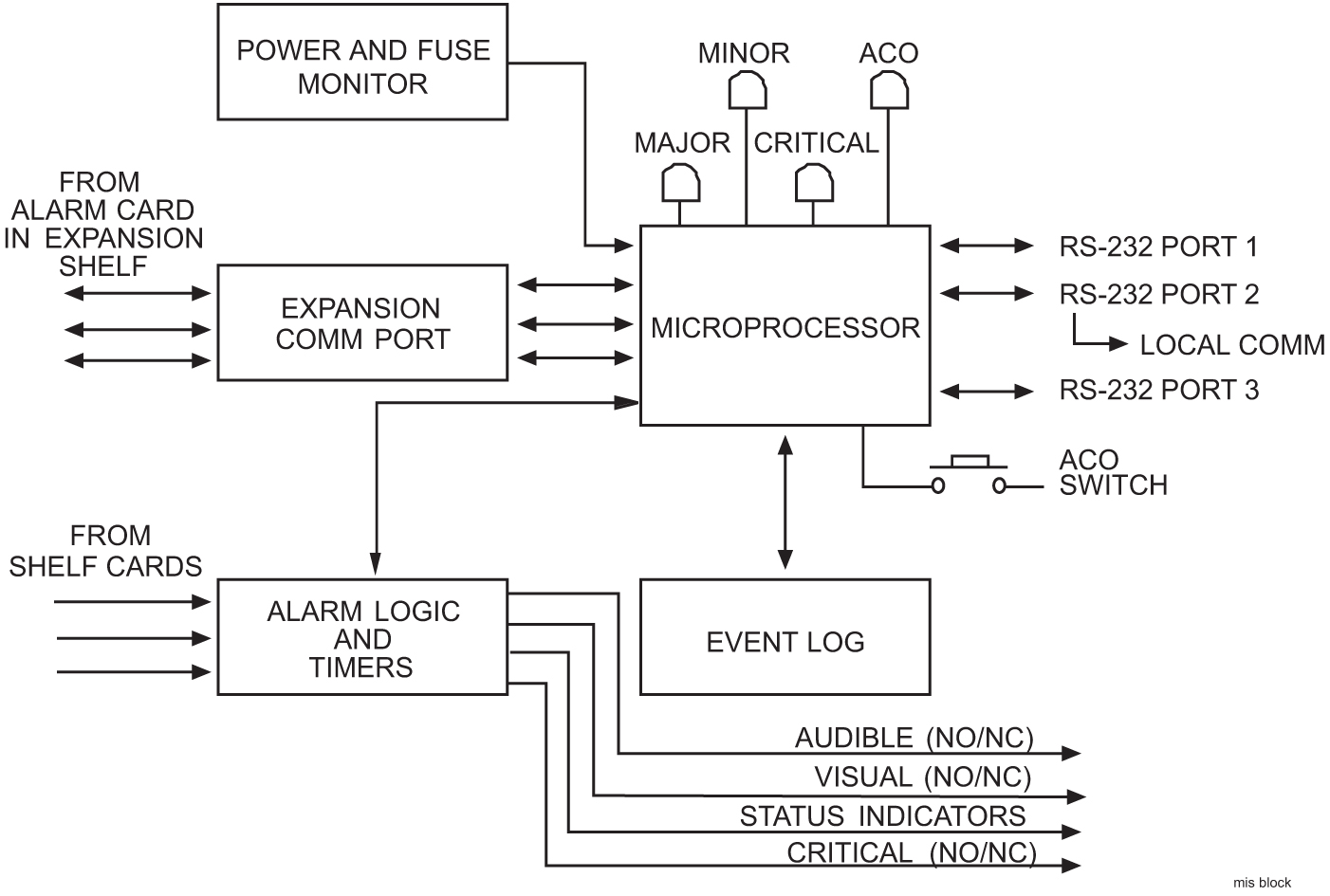
A front-panel Alarm Cut Off (ACO) push button, when pressed, silences the audible alarm and lights the ACO lamp. The ACO push buttons on all shelves in the system have the same effect. An external lead on the shelf backplane is provided for remote ACO operation.
The status of the shelf is available at the front panel lamps. A Major, Minor, or Critical lamp lights to indicate that one of those alarms exists on the shelf. The Fail lamp lights to indicate the MIS card has failed. The Alarm Cut Off (ACO) lamp lights when the ACO push button, is pressed to silence an audible alarm, before the alarm is cleared.
Critical Status Indicators Card
Two Card Indicator (CI)(P/N 804-0165-01) cards, provide input signal redundancy. Each CI card uses one Common Channel (CC) or one Digital Signal Level 1 (DS1) input as its timing reference. A switch on the CI card selects the type of input and the framing format, if DS1, of the input timing signal. Front panel lamps (CC and DS1) show which type of input is present.
Under normal operating conditions, CI A drives clock card A, and CI B drives clock card B. Both input reference signals are simultaneously monitored, and if an input fails, the clock card automatically switches to the other CI card, which then supplies both clock cards until the failed reference is restored. The SOURCEACTIVE lamp on the front panel indicates which CI card is on-line.
The CI card contains a source control circuit that causes the card to switch to the redundant CI card if the primary card, defined as the card currently in operation, fails.
Transfer between CI cards can be manually initiated by pressing the front-panel XFR switch on either CI card.
Switching activity between CI A and CI B will not cause the timing outputs to transmit phase hits, as the phase information of the active signal is transferred to the redundant CI card before switching. A Phase Locked Crystal Oscillator (PLXO) keeps the CI output stable while the transfer takes place. The PLXO also removes any phase jitter from the incoming signal before it passes the reference to the Timing Output Composite Clock Automatic (TOCA) cards.
If both CI cards fail, the clock cards go into holdover mode, and the system automatically uses the active clock card.
Stratum-3 Card
The Signal Transfer, Stratum-3 (ST-3) (P/N 804-0173-01) clock card provides timing signals at Stratum-3 accuracy to the TOCA cards. Select logic on eachTOCA card automatically chooses the input timing signal of the highest priority.
The ST-3 card is based on Phase Lock Loop (PLL) filtering and VXCO technology. The ST-3 is a relatively wide-bandwidth, fast-tracking clock that provides the necessary jitter attenuations and holdover stability. The PLL output is compared to a Temperature-Compensated Oscillator (TCXO), and an offset is generated to phase lock to the clock input, A or B.
If an input source is unavailable or has failed, the circuit goes into clock holdover mode at the frequency of the last valid input. If the holdover clock is started without an input reference, the ST-3 maintains accuracy at a predetermined rate.
If both ST-3 cards fail, a major system alarm is issued and the TOCA cards use the output of the clock input cards.
A phase build out circuit between the two clock input cards, A and B, and each ST-3 clock prevents transients from being transmitted to the Timing Output (TOCA) cards when there is a transfer between the two ST-3 cards.
TOCA and TOLA Cards
A Timing Output Composite Clock Automatic (TOCA)(P/N 804-0166-01) card, provides 10 composite clock timing outputs. There is a third TOCA card in the hot spare slot.
A source select circuit obtains the timing signal from either ST-3 clock card A or B. If no input timing signals are present, the TOCA card turns off both its ST-3 and INPUT lamps, lights the FAIL lamp, and mutes the outputs.
A Phase Lock Loop (PLL) circuit reconstitutes the internal timing signal. The reconstituted Computer and Communications (CC) timing signal is then applied to each port driver and sent through an impedance matching transformer.
The outputs are fed to the interface panel.
If the TOCA card fails or the output monitor determines that one to five output drivers have failed or are shorted, the front panel PORTALM lamp lights, and a minor alarm is generated.
Whenever manual or automatic protection switching takes place, the TOCA cards automatically transfer option switch settings to the hot spare, TOCA card.
Note:
An OEM purchased Timing Output Logic Automatic (TOLA) can be used as a composite clock source. The output cable connections are different from the TOCA card pin outs. See Installation for instructions about cabling both the TOCA and TOLA clock outputs.MCA Card
The Matrix Controller Automatic-5 card (MCA)(P/N 804-0251-01) controls the output protection switch matrix just above the holdover shelf and card slots on the hold over clock. It monitors the protection matrix push-button for activation. The MCA card requires the presence of at least one Hot Spare (HS) TOCA card in the slots provided immediately to the left of the MCA. Each holdover clock shelf contains slots for two hot spare TOCA cards.
The MCA card monitors the protection matrix for activation and the TO cards for port and fail alarms. When an active TO card indicates a failure or is removed, the MCA activates the relays and lamps in the protection matrix and switches in the appropriate hot spare TOCA card, if installed.
To ensure that a hot spare TOCA card cannot be accidentally placed in service or accidentally taken out of service, activating the hot spare TOCA card requires that the MCA detect a timing output failure or the front panel be pressed in the correct sequence. In addition, no switch occurs if the MCA card is physically removed from the shelf.
Note:
The MCA-5 can only switch from one TOCA to a hot spare TOCA at a time. There are six different TOCA card types and two hot spare TOCA slots per shelf.Figure 3-52 MCA-5 Card and Output Protection Matrix