2 System Overview
2.1 Introduction
This chapter introduces the hardware in Oracle Communication's signaling products. The hardware components to support its processor and feature applications include the following:
-
EAGLE
-
Multi-purpose Server (MPS)
Hardware Baselines in this guide lists specific hardware (required or configurable components) by part number for each system type and release.
Note:
Products are described generally in this chapter and in detail in Hardware Descriptions - EAGLE.In this document, modules or components that are used only in specific systems or releases are noted in the following syntax.
-
Components used only in EAGLE systems are labeled (EAGLE only).
-
Components that are specific to a system and release are labeled with the system name and release number. For example, (Sentinel 8.0 and later).
Note:
The term “module” refers to a hardware card provisioned with software. In some cases, EAGLE cards are referred to by the name of the module in which they function, rather than the card name that appears on the label of the card. For ordering or service purposes, customers should use the card name and part number printed on the card itself.
2.2 Oracle Communications EAGLE
The EAGLE is a large capacity, multi-functional, fully scalable Signaling Transfer Point (STP). High capacity and scalability allow the EAGLE to grow from a single-shelf, 80-link STP to a multi-frame, 2800-link STP. EAGLE also supports a variety of interface cards to support connectivity to a wide range of network elements. The EAGLE utilizes a modular design to provide ease of maintenance and expansion. Application and interface cards provide plug-and-play functionality. High reliability and redundancy maximize system availability.
The EAGLE consists of the following functional subsystems. Each subsystem is responsible for a specific task. These subsystems are depicted in the diagram below.
- Maintenance and Administration Subsystem (MAS)
- Communication Subsystem (Gigabit backbone)
- Application Subsystem
Figure 2-1 EAGLE Functional Diagram

The EAGLE hardware platform consists of various frame types. Each frame holds shelves or rack mounted equipment. The shelves hold the plug-in application and interface cards. Hardware Descriptions - EAGLE provides detailed information about component requirements and hardware configuration.
In addition, EAGLE has a clock derived from the Building Integrated Timing System (BITS). This connects to the 64KHz composite BITS signal and distributes clock signals to the rest of the cards in the systems.
Note:
See the section Timing Systems for information about High-Speed Source Timing and Time Slot Counter (TSC) Synchronization features.2.2.1 Maintenance and Administration Subsystem
The Maintenance and Administration Subsystem (MAS) is the central management point for the EAGLE. The MAS provides user interface, maintenance communication, peripheral services, alarm processing, system disk interface, measurements, and GLS and SNMP feature support. The EAGLE architecture provides Inter-processor Message Transport (IMT) connectivity directly to the maintenance and administration subsystem. The MAS includes redundancy ensuring continuous management control for the EAGLE. Management and redundancy is provided by use of two separate subsystem processors.
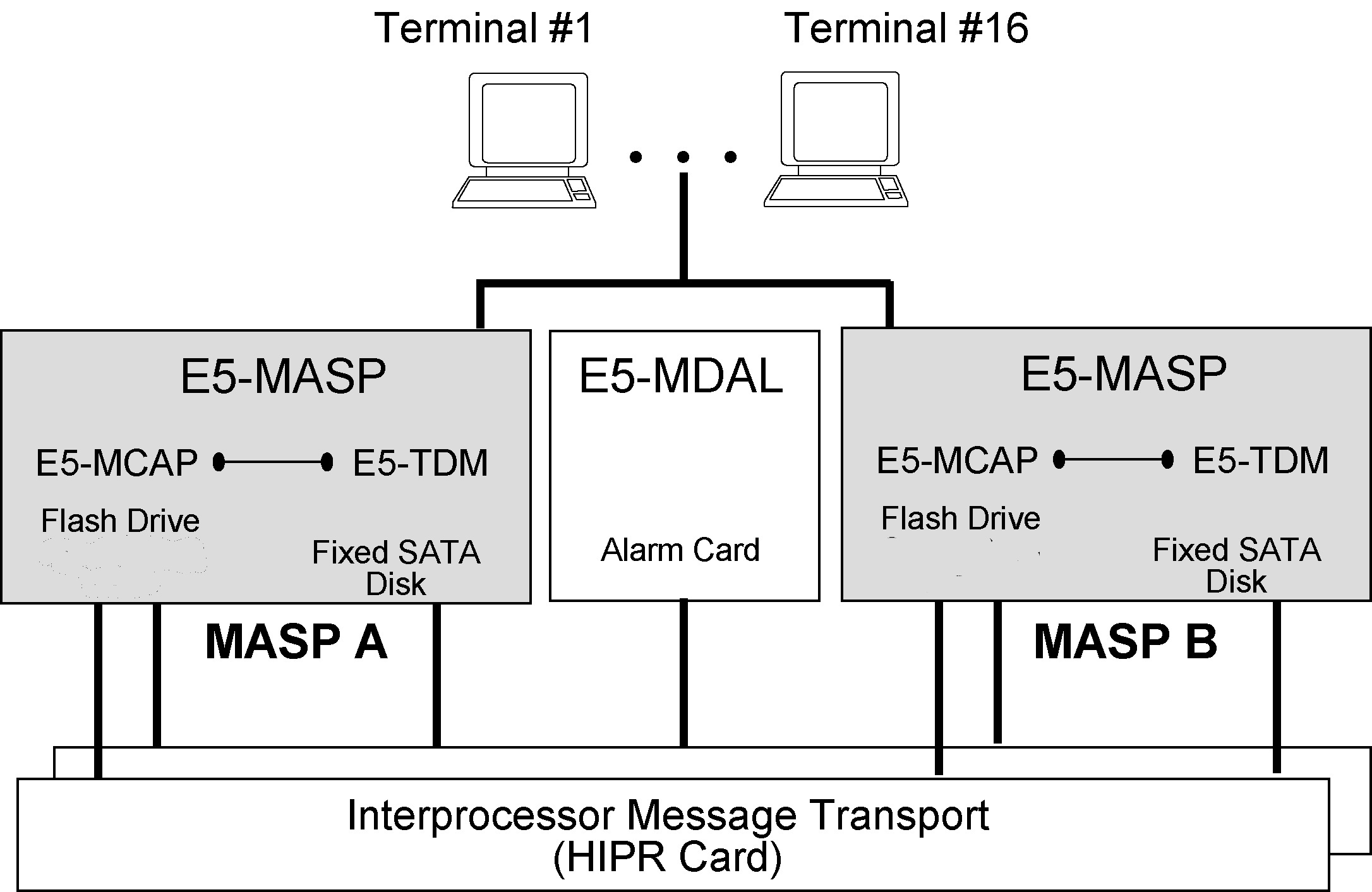
The MAS consists of two separate E5 Maintenance and Administration Subsystem Processor (E5-MASP) cards and a E5 Maintenance Disk and Alarm (E5-MDAL) cardMaintenance and Administration Subsystem Processor (MASP) cards and a Maintenance Disk and Alarm card (collectively referred to as control cards). The control cards are located in slots 1113 through 1118 of the EAGLE Control Shelf.
Note:
If FTRA is in use and E5-OAM cards are installed, EAGLE Release 41.0 and FTRA 4.2 are required.2.2.1.1 E5-based Control Cards
- One E5-based Maintenance Disk and Alarm (E5-MDAL) card.
- Two E5-based Maintenance and Administration Subsystem Processors (E5-MASP) cards. The E5-MASP card is a dual-slot physical assembly made up of the following two cards:
- E5-based Maintenance Communication Application Processor (E5-MCAP) card
- E5-based Terminal Disk Module (E5-TDM) card
Note:
See "Hardware Baseline Table" in Release Notes for compatible card part numbers.The E5-MASP is a dual-card/dual-slot assembly occupying slots 1113/1114 or 1115/1116 of the control shelf. The E5-MDAL is a dual-slot card occupying slots 1117/1118 of the control shelf.
Figure 2-2 E5-based Maintenance and Administration Subsystem Block Diagram
2.2.1.1.1 E5 Maintenance and Administration Subsystem Processor (E5-MASP) Card
The Maintenance and Administration Subsystem Processor (E5-MASP) cards contain all of the necessary logic to perform both application and communication processing of the data streams provided by the EAGLE. The cards provide connections to the IMT bus through the backplane and all of the necessary logic to perform both application and communication processing of the data streams through the EAGLE. The E5-MASP cards contains one fixed drive and USB connectors for two removable drives. The USB storage media in the flush-mounted USB port of the MASP card can be used for backups.
2.2.1.1.1.1 E5-MCAP
The E5-MCAP card is equipped with 4 GB of physical application processor memory. The primary data interface to the E5-MCAP is RS-232 interfaces (i.e.: terminals) through the E5-TDM.
The E5-MCAP card contains one latched USB port for use with removable flash media (“thumb drive”), and one flush-mounted USB port for use with a plug-in flash drive. The removable media drive is used to install and back up customer data. The flush-mounted USB port is used for upgrade and could be used for disaster recovery. The removable flash media is used as a replacement for the legacy Magneto-Optic (MO) Drive. The E5-MCAP card is a replacement for the obsoleted legacy GPSM-II card used for the MCAP function.
2.2.1.1.1.2 E5-TDM
The E5-TDM card contains four major subsystems: the Terminal Processor Subsystem, the System Clock/Control Subsystem, the SATA Subsystem, and a Power Subsystem. These subsystems provide the EAGLE 5 with 16 user-accessible terminals, distributes Composite Clocks and High Speed Source clocks throughout the EAGLE 5, distributes Shelf ID to the EAGLE 5, and disk storage for an E5-MCAP card. The E5-TDM card provides an interface to the E5-MDAL card for system alarms.
The E5-TDM card contains one fixed solid-state SATA drive that is removable and used to store primary and backup system databases, measurements, and Generic Program Loads (GPLs).
2.2.1.1.2 E5-MDAL
The E5-MDAL card processes alarm requests, provides general purpose relays, and provides fan control. There is only one E5-MDAL card in a control card set and it is shared between two E5-MASP cards. The E5-MDAL card is located in slots 1117 and 1118 of the control shelf.
Critical, major and minor system alarms are provided for up to 6 individual racks. In addition to the 3 system alarms, the E5-MDAL card provides the system audible alarm. All alarms are software controlled.
The E5-MDAL card provides control of fans on a per frame basis. The control logic allows for each fan relay to be set individually.
The E5-MDAL card does not contain a disk drive.
2.2.2 Communication Subsystem
The communication subsystem consists of the Inter-processor Message Transport (IMT) bus:
2.2.2.1 Inter-processor Message Transport
The Inter-processor Message Transport (IMT) bus is the main communications artery for all subsystems in the system. The IMT bus uses load sharing, so messages from the various subsystems are divided evenly across both buses. If one bus should fail, the other immediately assumes control of all messages.
IMT buses can function as a private LAN assigning internal IP addresses to LIM cards. By addressing cards on an internal LAN, the EAGLE and the Integrated Monitoring feature allows monitoring of SS7 links without external connections. SS7 link information from the EAGLELIM cards is collected by the Signaling Transport Cards (STCs) and is transferred to Expanded Service Platform (ESP) subassemblies. After processing in the ESP, the link information is forwarded to a monitoring server.
2.2.2.2 High-Speed IMT Packet Router 2
The High-Speed IMT Packet Router 2 (HIPR2) provides enhanced capabilities in existing EAGLE shelves by increasing system throughput. The HIPR2 enhances the IMT bus with the capability to operate the IMT inter-shelf bus at a rate of 2.5 Gbps. HIPR2 implements the HIPR scheme of transmitting data between shelves only when it is necessary.
Traffic between EAGLE cards on the same shelf will be switched directly to the destination slot and will not transit any other cards in the shelf. Traffic between shelves is not required to pass onto an intra-shelf IMT channel if it is not necessary.
As of Release 46.4, only the High-speed Fibre-channel cable (P/N 830-1344-XX) operating at a 2.5 Gbps inter-shelf bus rate is supported.
2.5 Gbps requires:
- All shelves within EAGLE be equipped with HIPR2
- High-speed Fibre-channel cables
2.2.3 Application Subsystem
The application subsystem consists of application cards. Application cards are capable of communicating with other cards through the redundant IMT buses. A Communications Processor (CP) on each application board provides control of communications from the cards to the IMT buses.
Software is downloaded to application cards on initial power-up from the Maintenance and Administration Subsystem Processors (MASP). Once EAGLE is loaded, software is downloaded to cards by the Operation Administration and Maintenance (OAM).
An Application Processor (AP) receives the software load on the application card. The type of software the AP receives depends on the function of the application board which is determined by the provisioning of the board. Presently, there are several types of application cards that support network specific functions:
-
Database Service Module (DSM) — EAGLE Application Processor(EPAP), Global System for Mobile Communications (GSM), EAGLE Local Number Portability (ELAP), and interface to Local Service Management System (LSMS).
-
E5-SM8G-B Database Service Module — EAGLE Application Processor (EPAP), Global System for Mobile Communications (GSM), EAGLE LNP Application Processor (ELAP), and interface to Oracle Communications LSMS (Local Service Management System). Supports 150K TPS GTT and 75K TPS G-Port features. The E5-SM8G-B module is capable of providing up to 13.6K TPS per card.
Note:
The E5-SM8G-B does not support ELAP with databases greater than 192M or EPAP with databases greater than 84M. -
E5-ENET-B — Has 4 physical 10/100 Mbps Ethernet ports. The PMC ports A0 and B0 are utilized as IP signaling link ports while PMC ports A1 and B1 support the Fast Copy feature when enabled. Each interface is independent of the others.
-
2 physical 10/100 Mbps Ethernet ports.
-
Supports STP Local Area Network function, and 10/100 Base-T ethernet links to the STP.
-
-
E5-MCPM-B - Requirement for the FTP measurements feature. The FTP measurements feature uses the MCPM card ethernet ports to transfer measurements information directly to a FTP server. Is used for nodes with link capacity of 2,400 (1,200 if 15 Minute Measurements is enabled) or greater.
-
Multi-Channel Interface Module, E5-E1T1-B — 8 HDLC channels for E1 or T1 protocols.
-
Multi-Port Link Interface Module, E5-ATM-B — SS7 links. Supports up to 3 links for ATMANSI and ATMITU application.
2.2.3.1 Generic Program Loads
Application software is downloaded to individual application cards by means of Generic Program Loads (GPLs). Hardware is defined to EAGLE by means of a series of administration commands. Software is then loaded from the fixed disk over the IMT bus directly to the cards. The type of the GPL loaded depends on the card that is chosen.
Example GPLs include the following:
- VSCCP —Signaling Connection Control Part. This software allows the Database Service Module (DSM) to be used as a memory board for Global Title Translation (GTT). Inbound SCCP messages from Link Interface Modules (LIMs) are sent to the DSM assigned to the LIM by system software. VSCCP software on the DSM performs the translation, and sends messages through the IMT back to the appropriate LIM, which routes messages to the destination. The VSCCP application can run on the DSM cards.
Caution:
It is recommended that cards running the VSCCP application be uniformly distributed in the EAGLE to provide a more even VSCCP load distribution. During normal operation unevenly distributed VSCCP cards in an EAGLE would not have any network or system impacts. However, should a particular VSCCP card database(s) become corrupted, inconsistent, or at a different level, depending on the amount of service provided by that card and the extent of the database issue, network impacts can occur. - SS7—This software provides access to remote SS7 network elements.
- EROUTE—Ethernet Routing transfers link information messaging from the EAGLE LIM cards to the Integrated Sentinel using TCP/IP and EAGLE Monitor Protocol (EMP). Implemented in Signaling Transport Cards (STC).
Note:
For a full and current list of GPLs, see "Generic Program Loads" in Release Notes.2.2.3.2 Link Interface Module
The application subsystem provides external services, relying on the Link Interface Module (LIM) as an interface. Each LIM provides one or or more line interfaces (Ethernet, E1/T1/J1, ATM) that can support 1 or more SS7 links (depending on configuration). A LIM consists of an application card equipped with a main assembly and an applique. This assembly provides level one and some level two functions on SS7 signaling links/line protocols.
The types of interfaces presently available through a LIM are:
2.2.3.3 Measurements Collection and Polling Module
The Measurements Collection and polling Module (MCPM) is an E5-MCPM-B card running MCPHC GPL.
Note:
The Measurements Platform IP Security feature requires an MCPM card.Note:
The MCPM card is a requirement for the FTP measurements feature. The FTP measurements feature utilizes the MCPM card ethernet ports to transfer measurements information directly to a FTP server.2.2.3.4 E5-MCPM-B Module
The E5-MCPM-B (P/N 870-3089-xx), Measurements Collection and polling Module (MCPM), is a requirement for the FTP measurements feature. The FTP measurements feature utilizes the E5-MCPM-B card ethernet ports to transfer measurements information directly to a FTP server.
Note:
The Measurements Platform IP Security feature requires E5-MCPM-B or EDSM-2G MCPM cards.2.2.3.5 E5-SM8G-B Module
Note:
All E5-based cards require HIPR2. For more information, see High-Speed IMT Packet Router 2.2.2.3.6 E5-B Interface Module
The E5-B interface module is a link interface card that utilizes an Embedded Processor Module (EPM-B) with an appliqué card. The E5-B card provides the EAGLE system a high performance general purpose-processing platform in a single-slot footprint. The E5-B card is used on existing EAGLE control and extension shelves.
Note:
As of Release 46.6, all cards and references to E5 and EPM cards refer to E5-B and EPM-B cards.The EPM appliqué cards provide LIM functionality such as E1/T1 or IP. The EPM accepts up two single-width or one double width PCI Mezzanine appliqué card(s). The EPM assembly contains all of the necessary logic to perform both application and communication processing of the data streams provided by the appliqué cards such as E1/T1 or IP. All EAGLE System interfacing to the EPM occurs through the EAGLE backplane signals and connects to the appliqué cards through the PCI Mezzanine Card (PMC) interface.
The EPM-B is a dual core base board with an appliqué interface to support the line interface cards. The EPM-B appliqué cards provide the same functionality as the obsoleted EPM cards, providing increased throughput and capacities.
Note:
The EPM-B cards may take up to 30 seconds after they are plugged in before any LED activity is observed.The types of E5-B cards presently available are:
- E5-E1T1-B (P/N 870-2970-xx)
- E5-ENET-B (P/N 870-2971-xx)
- E5-ATM-B (P/N 870-2972-xx)
- E5-MCPM-B (P/N 870-3089-xx)
2.2.3.6.1 E5-ATM-B Module
The E5-ATM-B card (P/N 870-2972-01) is a single slot card providing ATM over E1 and T1 connectivity for EAGLE control and extension shelves.
The card supports up to 3 links for ATMANSI and ATMITU application. The E5-ATM provides connectivity for two E1/T1 ports on the Port A backplane connector, allowing up to three links that may be provisioned. Both E1/T1ports can be accessed with a 2-port or 4-port cable. An interface adapter (P/N 830-1342-05) allows the two ports to be physically split to two different cables/patch panels. If it is desired to move the second E1/T1 port to the Port B backplane connector, then an adapter and another cable (1-, 2-, or 4-port) must be used.
Note:
Throughout this document, the term E5-ATM refers to the E5-ATM-B card (P/N 870-2972-01).2.2.3.6.2 E5-E1T1-B Module
The E5-E1T1-B card (P/N 870-2970-xx) is a single slot card providing eight trunk terminations. The eight E1/T1 ports reside on backplane connectors A and B. The E5-E1T1-B supports up to 64 signaling links of configurable channelized E1 or T1 connectivity OR two SE-HSL/ST-HSL signaling links.
All ports on a single board operate in the same trunk format, E1 or T1. However, it is possible to have a mixture of trunk formats in a node with some E5-E1T1s operating in T1 mode with others operating in E1 mode for gateway node scenarios.
Note:
Throughout this document, the term E5-E1T1 refers to the E5-E1T1-B card (P/N 870-2970-xx).2.2.3.6.3 E5-ENET-B Module
Note:
Throughout this document, the term E5-ENET refers to the E5-ENET-B (P/N 870-2971-xx) card.The E5-ENET provides support for the following:
- IPGWx
- SCTP, M3UA, SUA
- Up to 50 SCTP connections per card
- Up to 250 total E5-ENET cards per node. This total may be made up of cards running any application type ( IPGW, IPSG) and any adapter type.
-
IPSG
- M2PA, M3UA
- Up to 32 M2PA or M3UA links per IPSG E5-ENET card
- Up to 32 M2PA or M3UA associations per IPSG E5-ENET card
- Up to 128 SCTP associations per SLIC card
- Up to 250 total E5-ENET cards per node. This total may be made up of cards running any application type (IPGW, IPSG) and any adapter type.
- EROUTE (STC)
- TCP/IP
- Up to 32 cards per node
Note:
The E5-ENET is provisionable for these functions, but does not support multiple functions on a single card simultaneously.
Note:
The E5-ENET-B module (P/N 870-2971-xx) can run the IPS GPL to perform all functions as the E5-IPSM card. E5-ENET-B with IPS GPL can be exchanged with IPSM cards running IPS, without any changes in provisioning information. The E5-ENET-B running the IPS GPL supports SEAS Over IP functionality.The E5-ENET module has 4 physical 10/100 Mbps Ethernet ports. The PMC ports A0 and B0 are utilized as IP signaling link ports while PMC ports A1 and B1 support the Fast Copy feature when enabled. Each interface is independent of the others. The E5-ENET card and other DCM-class cards have backplane cable pinout differences requiring an adapter for the E5-ENET card.
2.2.4 Timing Systems
EAGLE uses synchronized timing systems to provide accurate reference standards to all cards on the IMT buses.
System Clock
EAGLE connects to the 64KHz composite Building Integrated Time System (BITS) clocks through two DB-15 style connectors on the backplane of the control shelf. The two clocks are labeled primary and secondary and are sent to both MASPs. Each MASP selects between two BITS clock signals to provide a system clock to the rest of the EAGLE. The system clock is used by Link Interface Modules (LIMs) and Signaling System #7 (SS7) Digital Service level-0 Applique (DS0A) signaling links, with each LIM selecting either clock A or clock B for its own use.
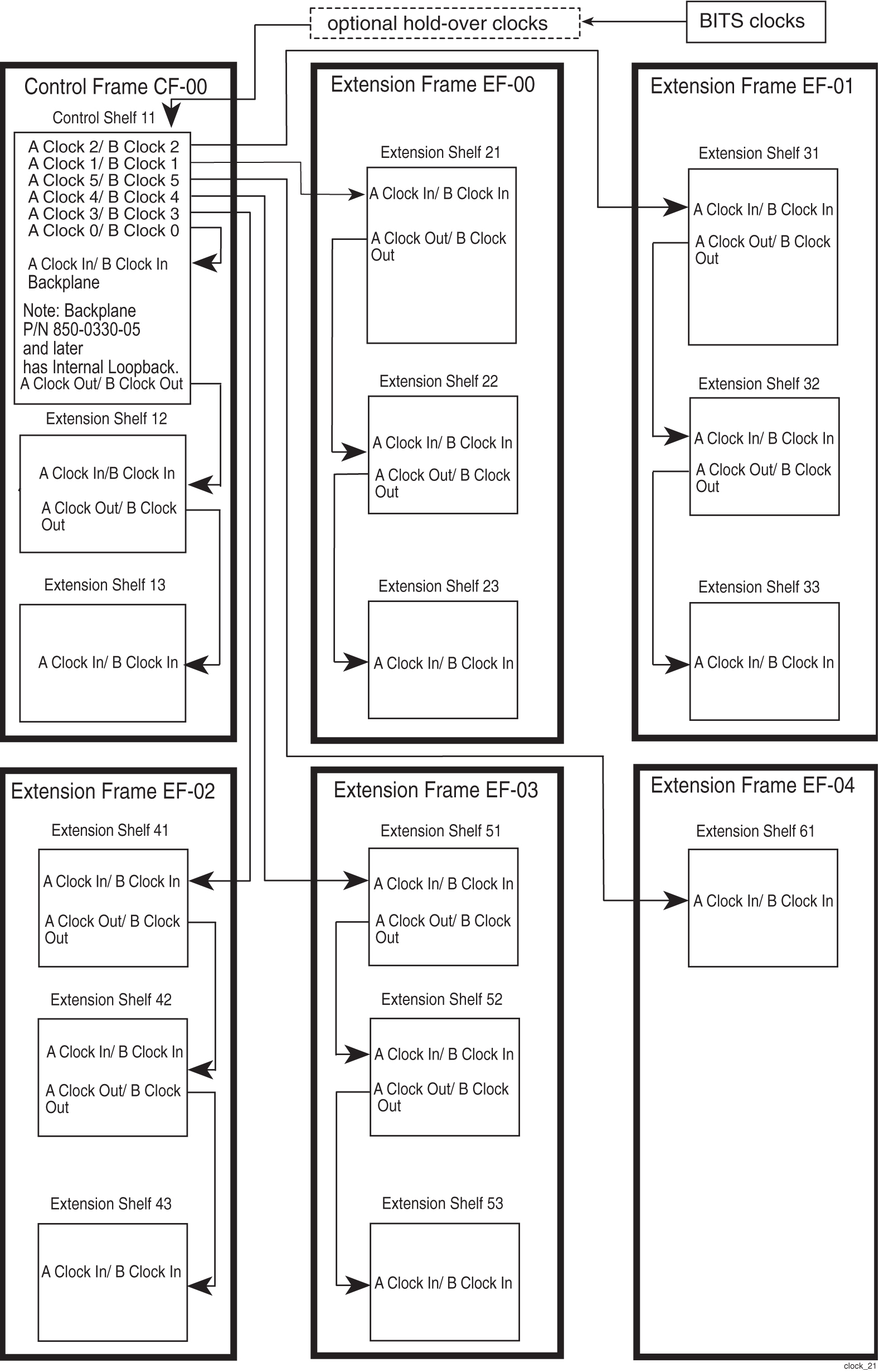
EAGLE also distributes system clocks to all frames. All shelves, both extension shelves and control shelves, provide “clock in” and “clock out” connections. Clock cables from the control shelf connect to the “clock in” connector on the top shelf of each frame. From the “clock out” connector on the top shelf of each frame, the clock signals are connected to the “clock in” connector of the middle shelf of the frame and from that shelf to the bottom shelf.
Holdover Clock
An optional holdover clock can maintain clock synchronization for EAGLE DS0A links during brief interruptions of the Building Integrated Timing System (BITS) clock signals. In accordance with Telcordia Technologies GR-1244-CORE, BITS clock outages of up to 15 seconds can be tolerated.
BITS Clock Routing
BITS clock signals A and B are routed through the holdover clock and then to the system, allowing the holdover clock to continue Stratum 3 clock signals to the EAGLE (see Figure 2-3).
Figure 2-3 Clock Routing
High-Speed Source Timing
The EAGLE can be configured with high-speed source timing capabilities. High-speed source timing allows synchronization of LIM cards at E1 or T1 rates. For more information about installing or upgrading to high-speed timing see the section on Source Timing in Installation Guide.
Time Slot Counter Synchronization
Time Slot Counter Synchronization (TSC) Synchronization allows all cards in the system that contain a Time Slot Counter (TSC) to synchronize with one another. The ability to have synchronized timing between cards is used in applications such as system wide message time stamping.
2.3 Multi-Purpose Server (MPS) Systems
The MPS system can be configured as an Oracle Communications EAGLE LNP Application Processor (ELAP) or EAGLE Application Processor (EPAP) server.
The MPS provides an interface between the customer provisioning network and the EAGLE SM cards. As the customer’s data is updated, the MPS stores the data and updates the SM cards. An MPS is usually co-located with an EAGLE. If you need to install an MPS at a distance from the EAGLE, contact the My Oracle Support (MOS) for assistance.
MPS running the EPAP software supports the GSM Flexible Numbering (G-Flex), GSM Mobile Number Portability (G-Port), INAP-based Number Portability (INP), and other features.
These features allow a subscriber to change location, service provider, or service while keeping the same directory number and ensures that subscribers receive the same freedom of choice for local service as they do with long-distance service providers.
MPS running the (ELAP) software supports the North American LNP feature.
The MPS uses the E5-APP-B card. For more information on this card, see Application B Card Hardware and Installation.
2.4 OEM Products
OEM-Based Servers
OEM-based products use Commercial Off-The-Shelf (COTS) servers, network elements, and peripheral components. Server hosts provide processing power and database storage capacity to deliver a scalable range of application specific services. Components can be configured redundantly to provide a high level of reliability in processing applications. One such OEM-based Product server currently being used is the Sun Netra T1DC200 server (used as Extended Services Platform (ESP) servers in the Integrated Sentinel systems).
OEM-based product capabilities are defined by specific application requirements. Optional processing components that provide application specific services can be integrated into OEM-based systems.
OEM-Based Network Elements
OEM-based products are configured as frame-mounted Local Area Networks (LAN) using Commercial Off-The-Shelf (COTS) routers, hubs, and switches. Typically OEM-based products are configured in redundant LANs with isolation and dial-up access IP links to customers networks.
Note:
Telco switches are provisioned in Eagle.Network components are typically configured in redundant pairs with dual power supply systems for reliability. Network components can include:
-
Routers
-
Hubs
-
Ethernet Switches
-
Application Servers
-
Optional components
OEM-Based Peripheral Components
OEM-based products use COTS peripheral components to support the server and network elements. Peripheral components can include:
-
Breaker panels
-
Workstations
-
Terminals
-
Switch boxes
-
Break-out boxes