A LED Information
A.1 Introduction
This section shows the card face plates and describes the Light Emitting Diodes (LEDs) for each card. This section assists maintenance personnel in troubleshooting.
EAGLE frames are configured with modules (cards) that provide specific functions and services. LEDs together with part numbers, text and bar codes are located on the faceplates of the cards. The cards are listed in alphabetical order of the full card name. Each card is identified by its acronym first, then by the full name of the card.
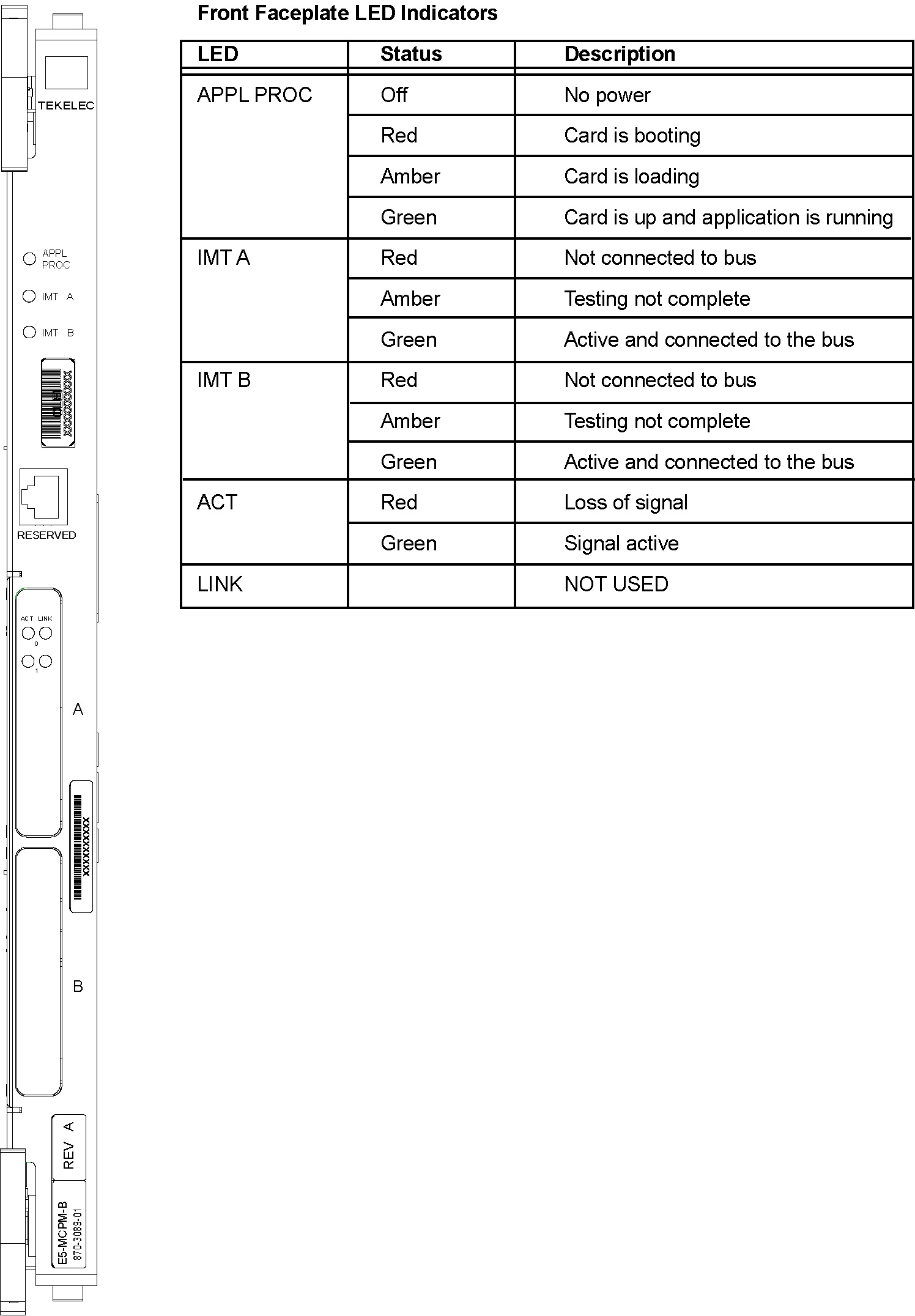
A.5 E5-ENET-B Interface Module
Figure A-4 E5-ENET-B Interface Module
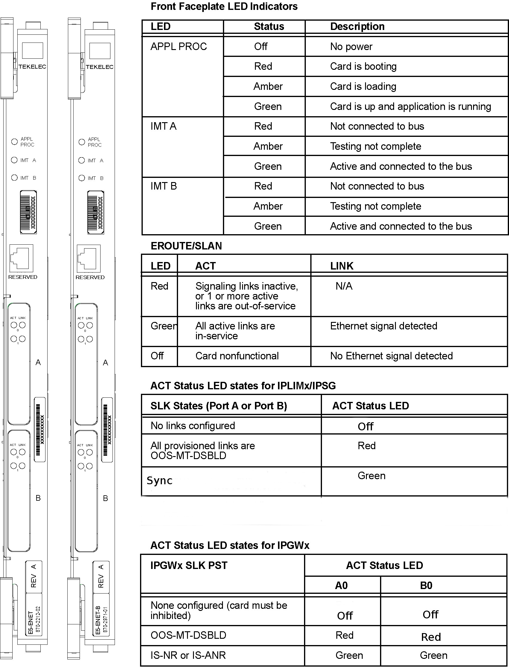
Note:
Must be used with the E5-MASP card.Note:
The E5-ENET-B is provisionable for multiple functions, but does not support multiple functions on a single card simultaneously.
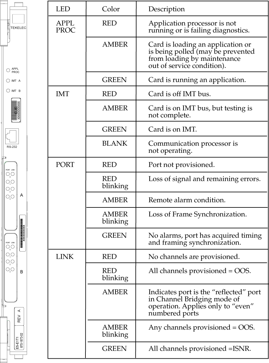
A.9 E5-SM8G-B Module
Figure A-8 E5-SM8G-B Interface Module
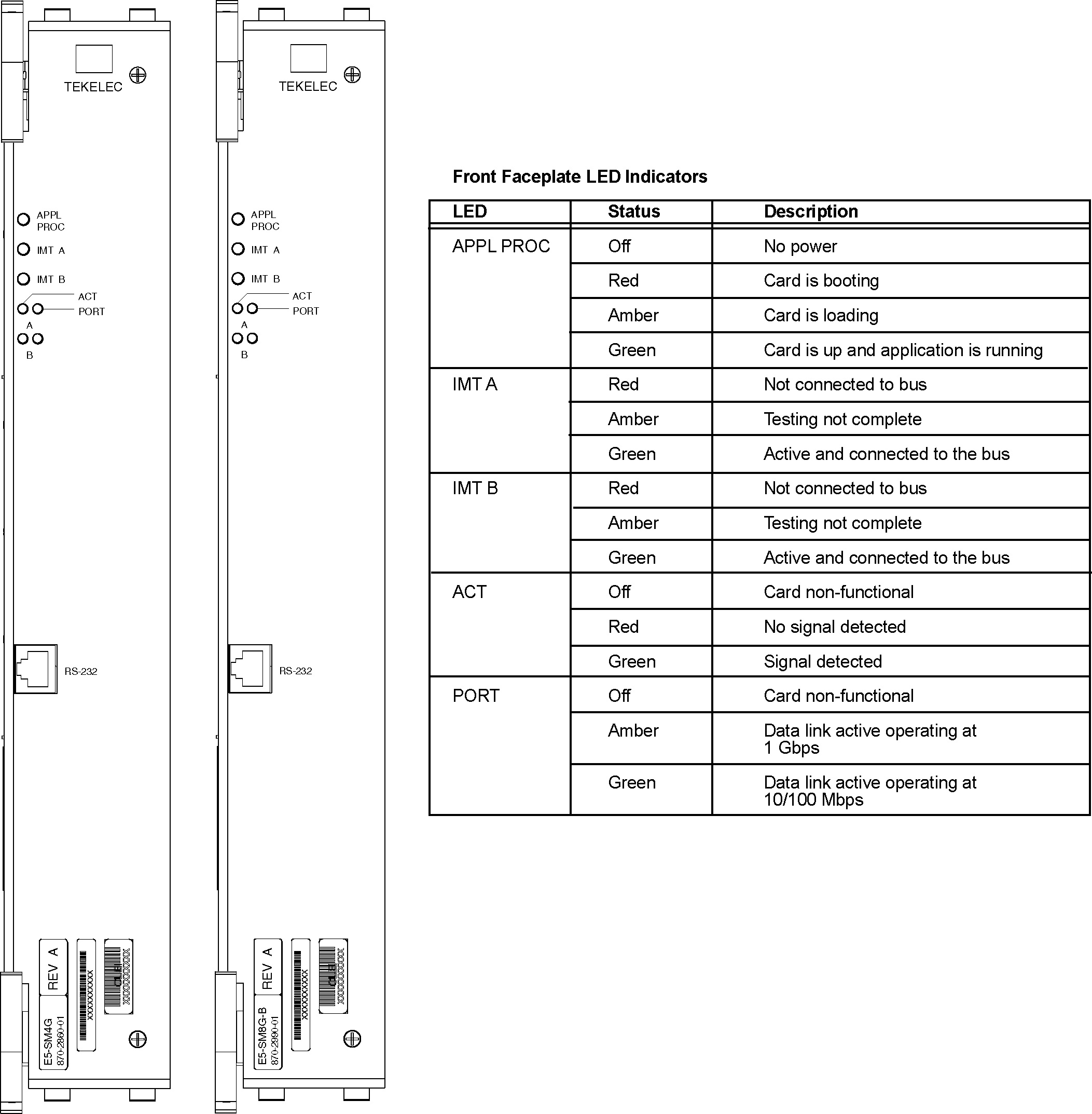
Table A-1 E5-SM8G Interface Module LEDs
| LED | Color | Descriptions |
|---|---|---|
|
APPL PROC |
Red |
Application processor is not running or is failing diagnostics. |
|
Amber |
Card is loading an application or is being polled (may be prevented from loading by maintenance-out-of-service condition) |
|
|
Green |
Card is running an application. |
|
|
IMT |
Red |
Card is off IMT bus |
|
Amber |
Card is on IMT bus, but testing is not complete. |
|
|
Green |
Card is on IMT bus |
|
|
Blank |
Communication processor is not operating. |
|
|
ACT |
Red |
No signal detected |
|
Green |
Signal detected |
|
|
Off |
Card nonfunctional |
|
|
PORT |
Amber |
Data link active operating at 1 Gbps |
|
Green |
Data link active operating at 10/100 Mbps |
|
|
Off |
Card non-functional |
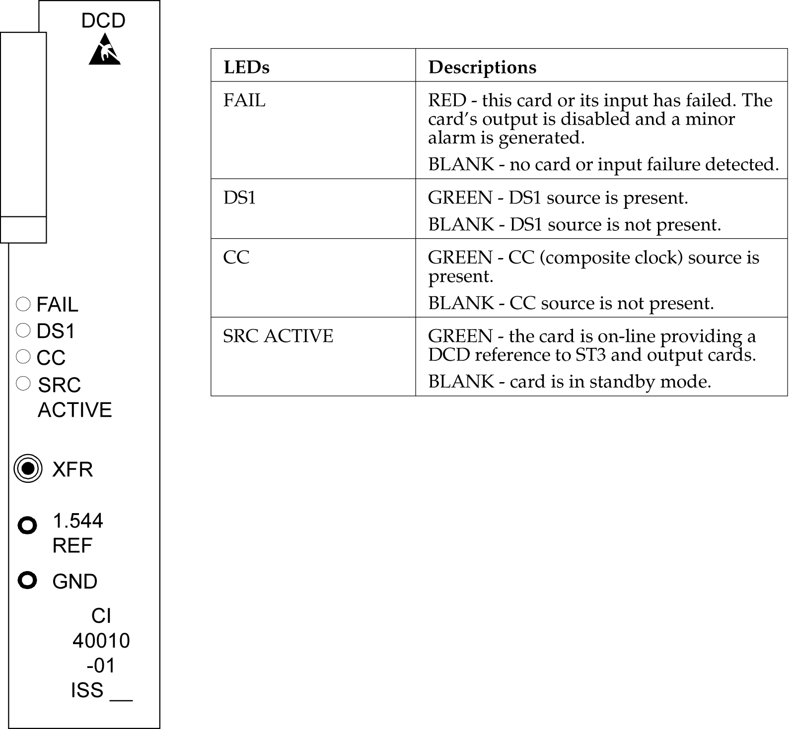
A.11 MIS, Maintenance Interface System, Holdover Clock
Figure A-10 Holdover Clock MIS Card LEDs
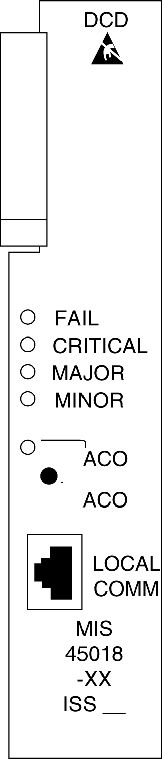
Table A-2 MIS LEDs
| LEDs | Descriptions |
|---|---|
|
FAIL |
RED – This card or its power supply has failed. BLANK – No card or power supply failure detected. |
|
CRITICAL |
RED – Holdover clock system has failed. BLANK – No holdover clock system failure detected. |
|
MAJOR |
RED – Holdover clock system or any holdover clock card has a major alarm. BLANK – No major alarm detected. |
|
MINOR |
YELLOW – Holdover clock system or any holdover clock card has a minor alarm. BLANK – No minor alarm detected. |
|
ACO |
GREEN – The ACO push button has been pressed to silence the alarm during an alarm state. |
A.12 MCA, Matrix Controller Assembly Card, Holdover Clock
Figure A-11 Holdover Clock MCA Card LEDs
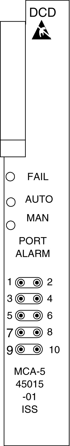
Table A-3 MCA LEDs
| LEDs | Descriptions |
|---|---|
|
FAIL |
RED – This card has failed or there is a loss of all input references to this card. BLANK – No card or input reference failure detected. |
|
AUTO |
GREEN – Indicates output failure was protected automatically. BLANK – No failures detected. |
|
MAN |
GREEN – Indicates output failure was protected manually. BLANK – No failures detected. |
A.13 SLIC Module
Alarms and LEDs
The SLIC has 21 LEDs visible on the faceplate. The LEDs are visible with the aid of a light pipe, which directs the light from the LED to the front panel.
Figure A-12 SLIC Module
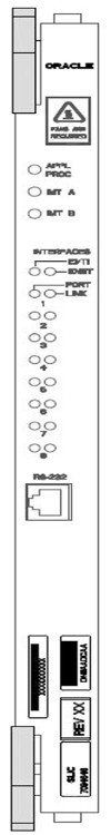
Table A-4 SLIC Front Panel LEDs
| LED Name | Control | Colors | Definition |
|---|---|---|---|
| APPL | FPGA / Application Software | Off / Red / Green |
Off - No power Red - Card is booting Green - Card is running Application |
| IMTA | LIIC FPGA / Communication Software | Red / Green |
Red -Not connected to BUS Green - Active and Connected to Bus Amber - MUX card on the same shelf is seated and not inhibited; bus not available |
| IMTB | LIIC FPGA / Communication Software | Red / Green |
Red - Not connected to BUS Green - Active and Connected to Bus Amber - MUX card on the same shelf is seated and not inhibited; bus not available |
| INTERFACES E1/T1 | FPGA / Application Software | Green / Off |
Green - Enabled Off - Disabled |
| INTERFACES ENET | FPGA / Application Software | Green / Off |
Green - Enabled Off - Disabled |
| PORT1-PORT8 | PHY / Application Software | Off / Red / Green |
Off - Not configured Red - Cable removed and/or not synced Green - 10/100Mb link speed |
| LINK1-LINK8 | FPGA / Application Software | Off / Red / Green |
Off - No SLKS configured Red - All Configured SLKS OOS Green - All SLKS aligned |
A.14 ST3, Stratum-3 Clock Card, Holdover Clock
Table A-5 ST3 LEDs
| LEDs | Descriptions |
|---|---|
|
FAIL |
RED – This card has failed. BLANK – No card failure detected. |
|
LOCK |
RED – Input has failed. BLANK – No input failure detected. |
|
REF A |
GREEN – Card is tracking the output of clock input card A. BLANK – Not tracking output of clock input card A. |
|
REF B |
GREEN – Card is tracking the output of clock input card B. BLANK – Not tracking output of clock input card B. |
Note:
If the FAIL and LOCK LEDs are both illuminated, the ST3 is in holdover mode and the card has not failed. Holdover Clock ST3 Card LEDs
A.15 TOCA, Timing Output Composite Automatic, Holdover Clock
Table A-6 TOCA LEDs
| LEDs | Descriptions |
|---|---|
|
FAIL |
RED – This card has failed or there is a loss of all input references to this card. BLANK – No card or input reference failure detected. |
|
PORT ALM |
RED – One to five outputs have failed or have been externally shorted. BLANK – No output failures detected. |
|
ST |
GREEN – An active clock is supplying the input reference for this card. BLANK – No active clock detected. |
|
INPUT |
GREEN – Card is receiving a reference signal from one or more of the following: clock input A, clock input B, clock card A, clock card B. BLANK – Card is not receiving a reference signal from any of the above sources. |
|
500’ |
Not used |
|
1000’ |
Not used |