6 Assemblies

6.1 Intra-system Cable Installation

This section covers the installation of cables that run within frames and between frames in a multiple frame installation. The cables covered in this section have been connected at one end in the factory and have connectors and are labeled at the other end for ease of installation. Consult the Equipment Specification for this installation and the label at the unconnected end of each cable to determine its connection point.

warning:

The intra-building port(s) of the equipment or subassembly is suitable for connection to intra-building or unexposed wiring or cabling only. The intra-building port(s) of the equipment or subassembly MUST NOT be metallically connected to interfaces that connect to the Outside Plant (OSP) or its wiring. These interfaces are designed for use as intra-building interfaces only (Type 2 or Type 4 ports as described in GR-1089-CORE, Issue 4) and require isolation from the exposed OSP cabling. The addition of Primary Protectors is not sufficient protection in order to connect these interfaces metallically to OSP wiring.

The cables covered in this section are:

  • Interprocessor Message Transport (IMT) cables

  • Clock/Alarm cables

  • Interface cables

For additional information concerning cables and cable replacement, see Cables and Adapters.

Recommended Tools

Oracle tools should be labeled “Property of ORACLE” with either a press-on Field Tool Identification label or Field Tool Identification wrap.

  • Safety glasses

  • Tie-wrap tool

  • Flush cutters

  • Slotted screwdriver, 1/8-inch blade with 8-inch shank preferred

  • Phillips screwdrivers #2 and #3

  • Wrist strap

6.1.1 Install IMT Cables

The Interprocessor Message Transport (IMT) cables are specific lengths, based on their application. Termination information is furnished on the cable labels. Refer to Cables and Adapters and Part Numbers

danger:

Always wear a wrist strap or other electrostatic protection when handling printed circuit cards and other electrostatic-sensitive devices.

Procedure — Install IMT Cables

  1. Route the cable and connect to the backplane connector specified on the cable label.
    The IMT cables route down the left side of the frames, see Figure 6-4.
  2. For the IMT cables, tighten the barrel securely on each connector.

    Figure 6-1 Interprocessor Message Transport Cables


    img/t_install_imt_cables_im-fig1.jpg

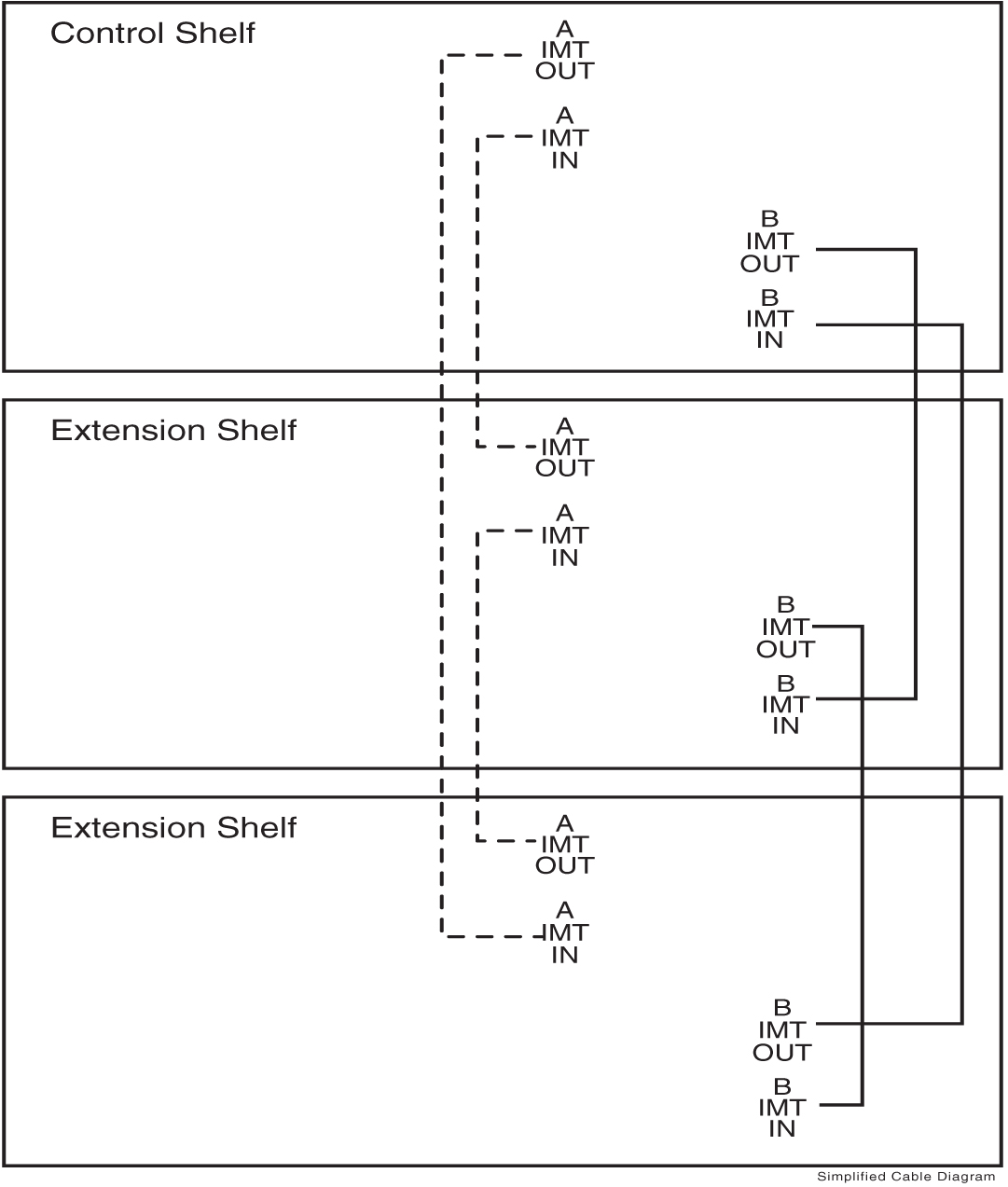
  3. Dress each cable and secure with cable ties.
    Ensure that each cable tie strap is cut flush with the cable tie head so that no sharp edges are exposed.

    Figure 6-2 Three-Frame Configuration


    img/t_install_imt_cables_im-fig2.jpg

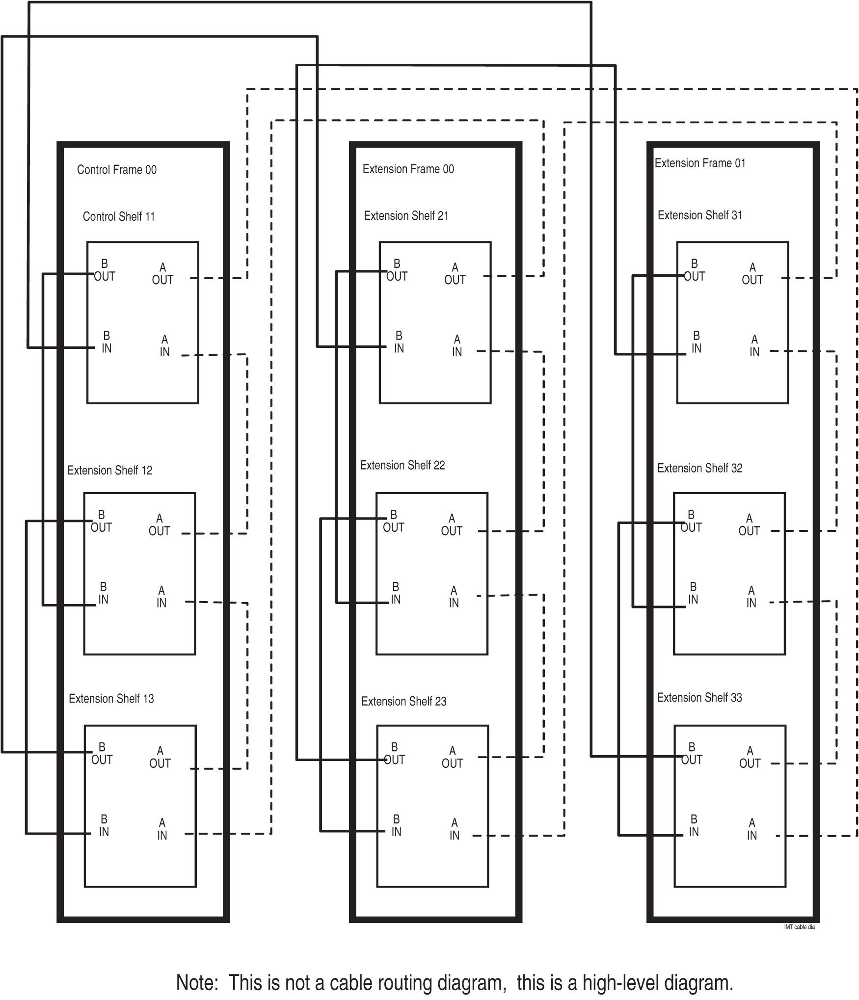
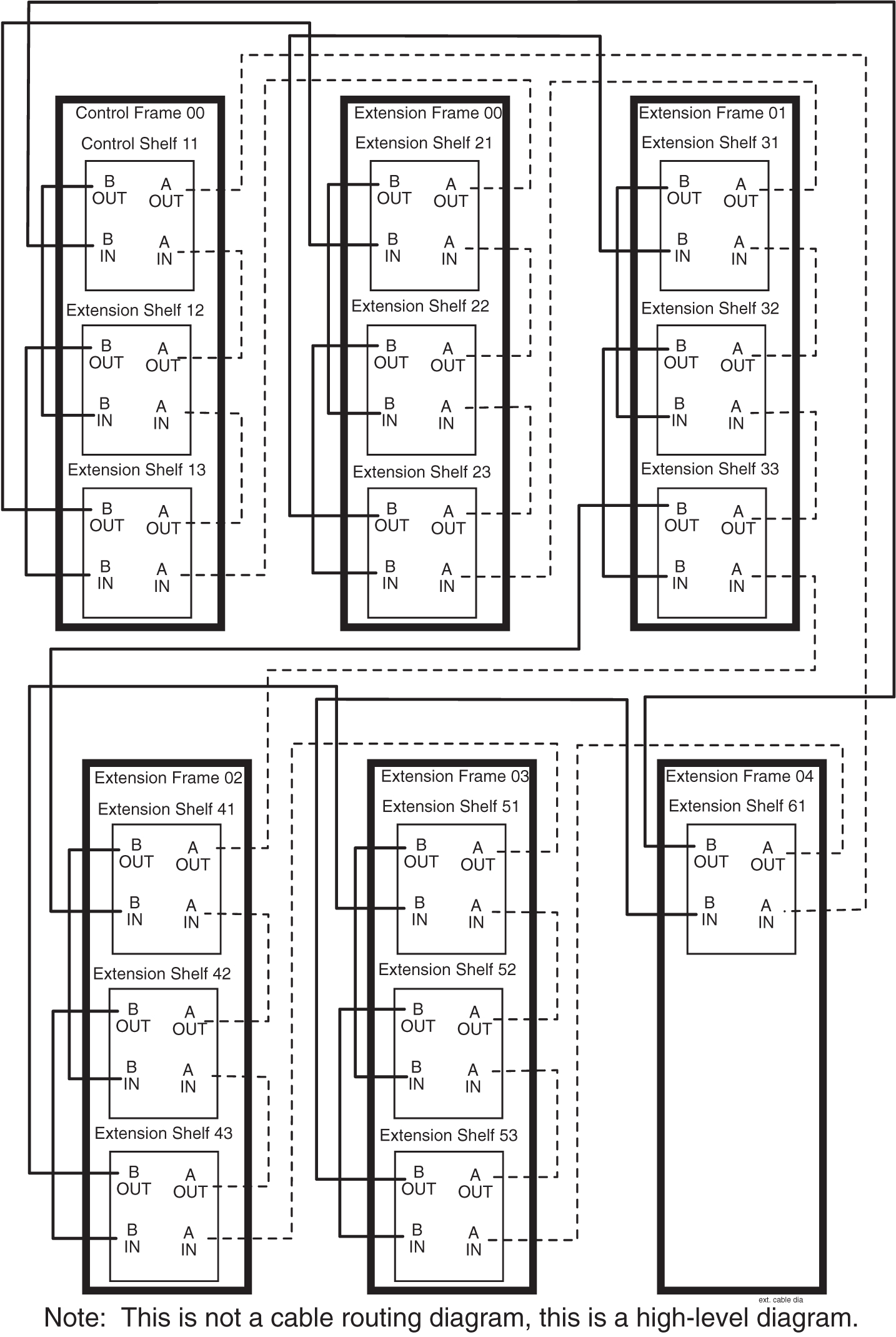
    Figure 6-3 Six-Frame Configuration


    img/t_install_imt_cables_im-fig3.jpg

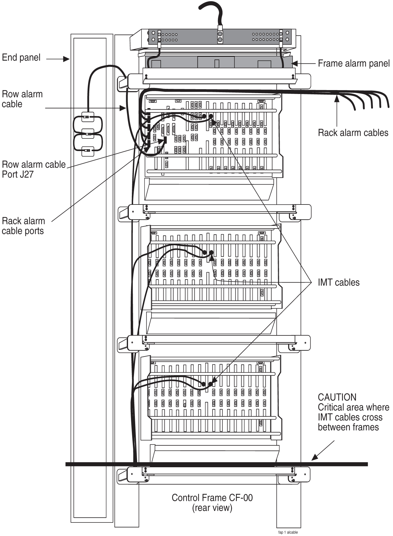
6.1.1.1 Rack Alarm and Row Alarm Cable Routing

The rack alarm cable leads from ports in the control backplane and connects up to six frames in the row. See Figure 6-4 and A Clock and B Clock Cable Replacement.

The row alarm cable leads from J34 on backplane 850-0330-06/07 or 7333412 on the control shelf backplane and terminates in the control frame end panel.

Note:

The clocking and fan control signals used to support frame 6 and frame 7 are eliminated in the 850-0330-06 or -07 version and later of the Control Shelf Backplane because those frames are no longer supported in the EAGLE STP system.

Figure 6-4 Control Shelf Cabling


img/c_rack_alarm_and_row_alarm_cable_routing_im-fig1.jpg

6.1.2 Interface Cable Installation

The procedure in this section is used to install the interface cables. The interface cables, one per signaling link, contain solid conductor twisted pairs for both directions of transmission in a single shield. They have connectors at one end for connection to the system backplanes.

Note:

Run Link Interface Module (LIM) cables on traverse arms, behind IMT and clock cables.

The ends without connectors are normally terminated on a DSX cross-connect panel with wire-wrap terminals.

  1. Secure the connector to the designated receptacle on the DSX panel.
  2. Plug the connector in and turn one of the connector screws to start the screw into the threaded hole.
  3. Start the other screw into the other threaded hole.
    With both screws started alternate tightening the screws until both screws are snug, finger tight. Complete tightening to FIVE inch-pounds only, NO MORE or the screws will twist off and the connection can be broken.

    Note:

    Tightening must be done in an alternating pattern.
    Termination information is furnished in the Cable Running List in the Equipment Specification for the site. See the Interface Cable Installation Order for a typical interface cable cross-connect panel connection.

    Note:

    All cable ends must be labeled “TO” and “FROM” location information from Port to Backplane.
6.1.2.1 Interface Cable Installation Order

Interface cables should be installed in the following order.

6.1.2.1.1 Control Frame CF-00 Backplane

(P/N  850-0330-04/06/07) or 7333412 

Control shelf 11

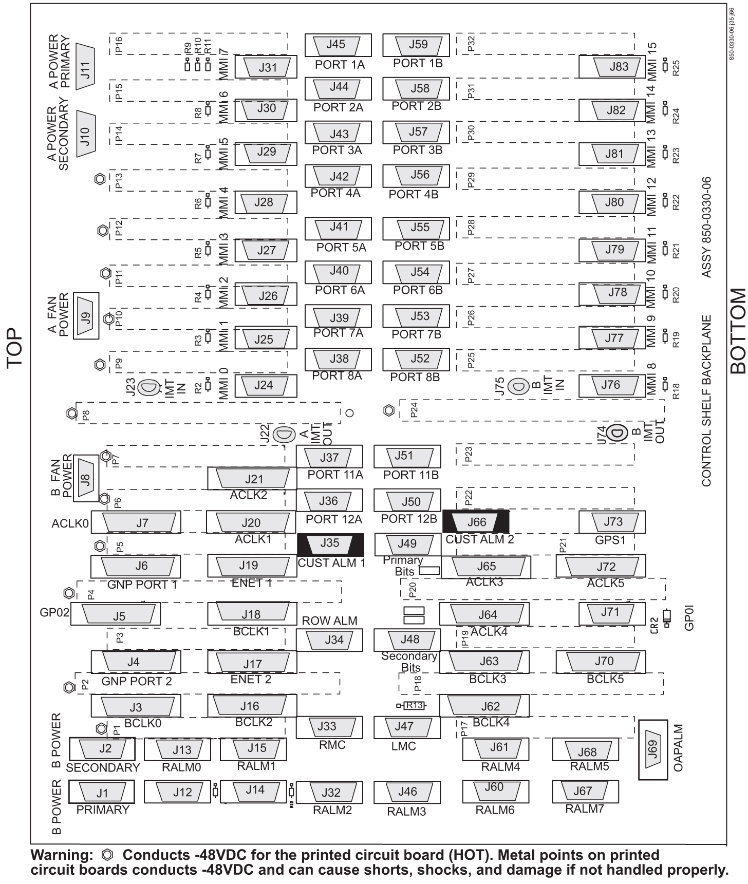
1101 A through 1108 A (P/N 850-0330-06 or -07 connectors J45 through J38)

1101 B through 1108 B (P/N 850-0330-06 or -07 connectors J59 through J52)

1111 A through 1112 A (P/N 850-0330-06 or -07 connectors J37 and J36)

1111 B through 1112 B (P/N 850-0330-06 or -07 connectors J51 and J50)
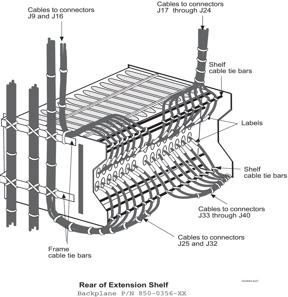
Extension shelf 12

1201 A through 1208 A (connectors J24 through J17)

1201 B through 1208 B (connectors J40 through J33)

1211 A through 1218 A (connectors J16 through J9)

1211 B through 1218 B (connectors J32 through J25)

Extension shelf 13 Backplane (P/N 850-0356-03)

1301 A through 1308 A (connectors J24 through J17)

1301 B through 1308 B (connectors J40 through J33)

1311 A through 1318 A (connectors J16 through J9)

1311 B through 1318 B (connectors J32 through J25)

6.1.2.1.2 Extension Frame EF-00

Extension shelf 21

2101 A through 2108 A (connectors J24 through J17)

2101 B through 2108 B (connectors J40 through J33)

2111 A through 2118 A (connectors J16 through J9)

2111 B through 2118 B (connectors J32 through J25)

Extension shelf 22

2201 A through 2208 A (connectors J24 through J17)

2201 B through 2208 B (connectors J40 through J33)

2211 A through 2218 A (connectors J16 through J9)

2211 B through 2218 B (connectors J32 through J25)

Extension shelf 23

2301 A through 2308 A (connectors J24 through J17)

2301 B through 2308 B (connectors J40 through J33)

2311 A through 2318 A (connectors J16 through J9)

2311 B through 2318 B (connectors J32 through J25)

6.1.2.1.3 Extension Frame EF-01

Extension shelf 31

3101 A through 3108 A (connectors J24 through J17)

3101 B through 3108 B (connectors J40 through J33)

3111 A through 3118 A (connectors J16 through J9)

3111 B through 3118 B (connectors J32 through J25)

Extension shelf 32

3201 A through 3208 A (connectors J24 through J17)

3201 B through 3208 B (connectors J40 through J33)

3211 A through 3218 A (connectors J16 through J9)

3211 B through 3218 B (connectors J32 through J25)

Extension shelf 33

3301 A through 3308 A (connectors J24 through J17)

3301 B through 3308 B (connectors J40 through J33)

3311 A through 3318 A (connectors J16 through J9)

3311 B through 3318 B (connectors J32 through J25)

6.1.2.1.4 Extension Frame EF-02

Extension shelf 41

4101 A through 4108 A (connectors J24 through J17)

4101 B through 4108 B (connectors J40 through J33)

4111 A through 4118 A (connectors J16 through J9)

4111 B through 4118 B (connectors J32 through J25)

Extension shelf 42

4201 A through 4208 A (connectors J24 through J17)

4201 B through 4208 B (connectors J40 through J33)

4211 A through 4218 A (connectors J16 through J9)

4211 B through 4218 B (connectors J32 through J25)

Extension shelf 43

4301 A through 4308 A (connectors J24 through J17)

4301 B through 4308 B (connectors J40 through J33)

4311 A through 4318 A (connectors J16 through J9)

4311 B through 4318 B (connectors J32 through J25)

6.1.2.1.5 Extension Frame EF-03

Extension shelf 51

5101 A through 5108 A (connectors J24 through J17)

5101 B through 5108 B (connectors J40 through J33)

5111 A through 5118 A (connectors J16 through J9)

5111 B through 5118 B (connectors J32 through J25)

Extension shelf 52

5201 A through 5208 A (connectors J24 through J17)

5201 B through 5208 B (connectors J40 through J33)

5211 A through 5218 A (connectors J16 through J9)

5211 B through 5218 B (connectors J32 through J25)

Extension shelf 53

5301 A through 5308 A (connectors J24 through J17)

5301 B through 5308 B (connectors J40 through J33)

5311 A through 5318 A (connectors J16 through J9)

5311 B through 5318 B (connectors J32 through J25)

6.1.2.1.6 Extension Frame EF-04

Extension shelf 61

6101 A through 6108 A (connectors J24 through J17)

6101 B through 6108 B (connectors J40 through J33)

6111 A through 6118 A (connectors J16 through J9)

6111 B through 6118 B (connectors J32 through J25)

6.1.2.2 Recommended Tools

Oracle tools should be labeled “Property of ORACLE” with either a press-on Field Tool Identification label or Field Tool Identification wrap.

  • Safety glasses

  • Tie-wrap tool

  • Diagonal cutters

  • Flush cutters

  • Slotted screwdriver, 1/8-inch blade with 8-inch shank

  • 3/8-inch shrink-wrap

  • Heat-shrink gun (hot air blower)

  • Torque screwdriver

  • Wire-wrap gun

  • 22-gauge wire-wrap bit

  • 24-gauge wire-wrap bit

Interface Cable Installation

Examine the labels on the ends of the interface cables to determine the system backplane connection location “FROM” information on label and DSX cross-connect panel location “TO” information on label for each cable.

Run the cables on the cable rack to the cross-connect panel on the Miscellaneous Frame in groups of eight. There are four groups per extension shelf and groups per control shelf (a total of 20 per control shelf). The jack numbering on the cross-connect panel determines which side of the frame to run the cable. Viewing the frame from the rear, cables going to jacks #1 through #32 are run on the right side of the frame and cables #33 through #64 are run on the left side of the frame.

Procedure — Install Interface Cable

  1. Secure connector to its respective receptacle on the backplanes. See Interface Cable Installation.

  2. Tie cables to the shelf cable tie bar at the rear of the shelf.

  3. Pull slack from each cable towards the cross-connect panel.

  4. Dress cable bundles neatly and tie to the cable tie bars at the side of the frame.

  5. Lace the bundles to the cable rack.

    Note:

    All cables must be laced onto the top traverse arms of each frame. Only lacing is used from the top traverse arms and above, on the frame and on the cable rack.

    Note:

    Where the cable leaves the cable rack, the cable must be protected with fiber paper through out the system.

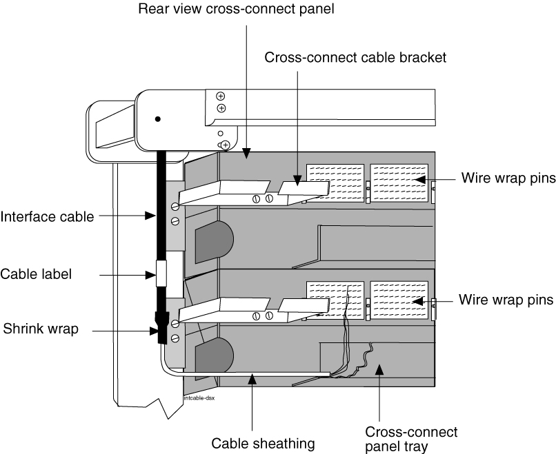
Procedure — Preparing Cables for Wire-Wrap

  1. Remove the insulation from the cable where it is even with the bracket of the associated cross-connect panel as shown in Figure 6-5.

    Note:

    Do not remove the inner sheath.
  2. Attach the label for the cross-connect end of the cable approximately two inches above the end of the insulation.
  3. Apply a 1-1/2-inch length of 1/4-inch shrink-wrap tubing, taking care to center the tubing on the end of the cable insulation.
    Use heat gun to shrink tubing.

    Note:

    Do not overheat the cable.
  4. Run the interface cable wires through the cross-connect panel cable tray.
  5. Remove the cable sheathing directly below the cross-connect jack.
  6. Cut the wires to length, strip and wire-wrap to the cross-connect panel.
  7. Cut the cable tie strap flush with the cable tie head.

    Figure 6-5 Interface Cable Cross-Connect Panel Connection


    img/t_recommended_tools_6_im-fig1.jpg

  8. Label DSX panel

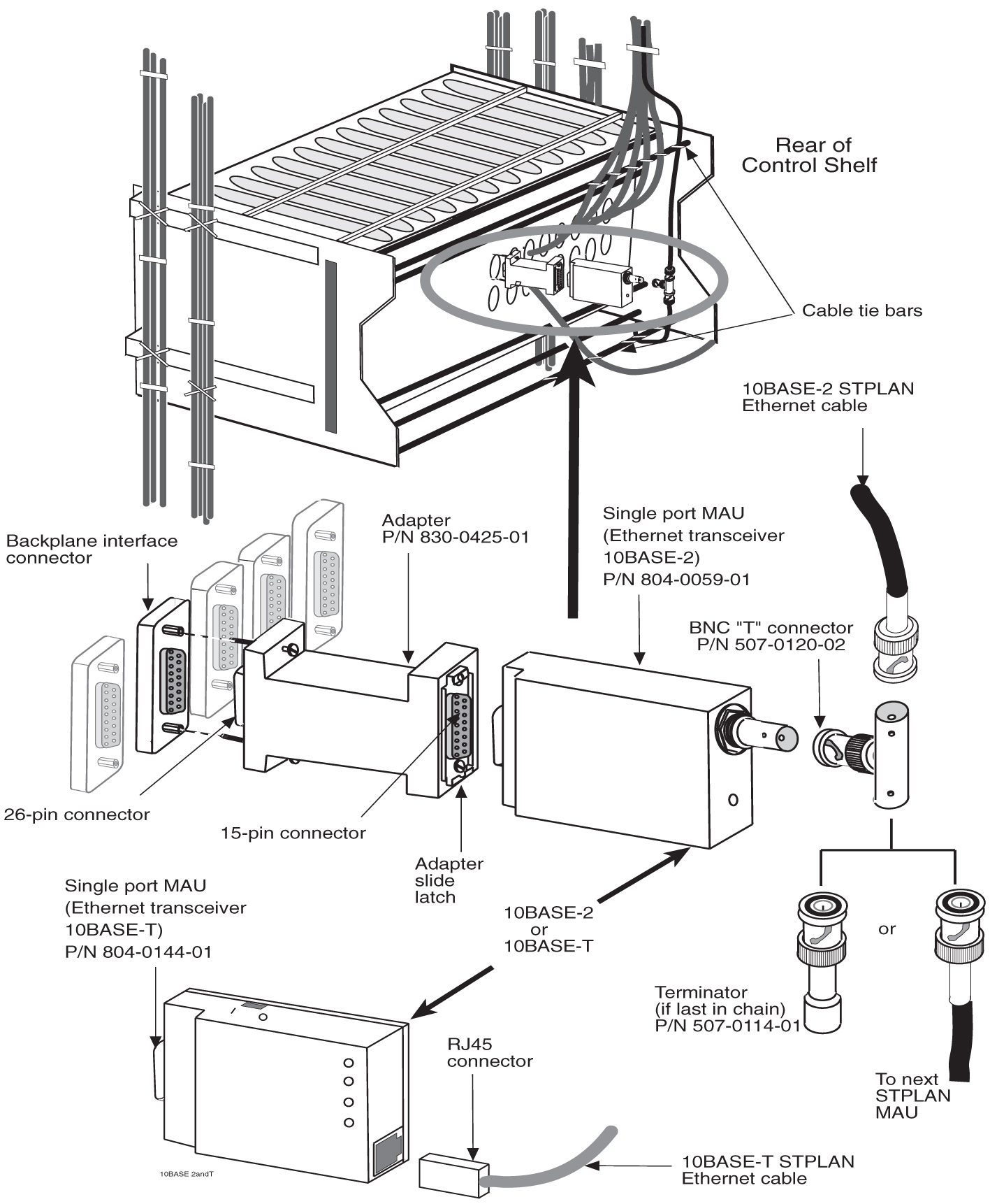
6.1.3 LAN Ethernet Cable Installation for ACM

This section contains the procedures for installing the Local Area Network (LAN) Ethernet cable, see Figure 6-7 for the location of equipment. The LAN provides selected data to a remote host system through an Ethernet network. In the system, communications with the host is interfaced through an Application Communication Module (ACM). Communications with the ACM is accomplished through:

  • The system backplane interface connector associated with that particular ACM

  • A 15-pin to 26-pin adapter

  • A single port Ethernet transceiver Media Access Unit (MAU)

  • A 10BASE-2 Thin net coax connection or 10BASE-T twisted pair connection to the Ethernet network

6.1.3.1 Customer Supplied Ethernet Cable Requirements

If a customer chooses to supply their own Ethernet cables for EAGLE (customer-supplied cables are not subject to Oracle warranty), the following requirements must be met:

Customer-supplied Ethernet cables for EAGLE must be shielded, meet the industry standard, and avoid dissimilar metals at the RJ45 connector interface. The required standards include:

Metallization (30 or 50µ in. Au over 50µ in. Ni), at the connector interface. The wire required follows: Category 5E SCTP 26AWG 7/34 tinned copper 4 PR per IEC 11801, TIA/EIA 568B, EN 50173 with Overall shield, 26 AWG stranded T.C. drain wire, UL CMR, C(UL) CMR rating, or other agency listing.

Signaling Cables (for example, T1, ATM) are EAGLE proprietary and must be purchased from Oracle.

6.1.3.2 Recommended Tools

Oracle tools should be labeled “Property of ORACLE” with either a press-on Field Tool Identification label or Field Tool Identification wrap.

  • Safety glasses

  • Diagonal cutters

  • Coax crimping tool

  • Tie-wrap tool

  • Flush cutters

  • Slotted screwdriver with 1/8-inch blade with 8-inch shank

  • Multimeter

LAN Ethernet Cable Installation

  1. Run each 10BASE-2 Thin net coax cable or 10BASE-T twisted pair cable from the Ethernet network onto the cable rack.
  2. Run each cable down the respective side of the system, outside the cable tie bars, and around the top or bottom edge of the terminating shelf.

    Note:

    Use Table 6-1 to locate the ACM backplane interface connector for each Ethernet connection.
    The ACM location number in Table 6-1 consists of the shelf (left two digits) and the slot (right two digits) that contain the ACM. For example, an ACM location of 1108 indicates slot 08 of the Control Shelf (shelf 11). For ACMs located in an Extension Shelf, replace “XX” in the ACM location number with the number for that shelf (12, 13, 21, 22, 23, 31, 32, or 33).

    Table 6-1 ACM Card and Backplane Interface

    Shelf ACM Location Backplane (P/N 850-0330-03/04/06) Connector

    Control Shelf

    1101

    J45

    1102

    J44

    1103

    J43

    1104

    J42

    1105

    J41

    1106

    J40

    1107

    J39

    1108

    J38

    1111

    J37

    1112

    J36


    Backplane (P/N 850-0356-03) Connector

    Extension Shelves (XX is shelf location)

    XX01

    J24

    XX02

    J23

    XX03

    J22

    XX04

    J21

    XX05

    J20

    XX06

    J19

    XX07

    J18

    XX08

    J17

    XX11

    J16

    XX12

    J15

    XX13

    J14

    XX14

    J13

    XX15

    J12

    XX16

    J11

    XX17

    J10

    XX18

    J9

  3. Attach a BNC connector to the end of the 10BASE-2 coax cable.
    If necessary, attach an RJ45 type connector to the end of the 10BASE-T twisted pair cable.
  4. Secure each cable, see Figure 6-7 to its respective connector on the system backplane as follows:
    1. Plug the 26-pin side of the adapter into the backplane interface connector.
    2. Start one of the adapter connector screws, and then alternately tighten the two adapter screws.
    3. Ensure the adapter slide latch is in the unlocked (up) position see to Figure 6-6.
    4. Plug the single port MAU into the adapter.
    5. Move the adapter slide latch to the locked (down) position.
    6. For the 10BASE-2 MAU, push the BNC connector on the coax cable onto the MAU and lock the connector in place by twisting the connector clockwise.
      For a 10BASE-T MAU, push the RJ45 connector into the MAU until it snaps into place.

      Figure 6-6 Adapter Slide Latch


      img/t_recommended_tools_7_im-fig1.jpg

  5. Tie-wrap each cable to the cable tie bar at the rear of the shelf and then to the cable tie bars at the side of the frame.
  6. Pull the slack back toward the other end of the cables and lace to the cable rack.
  7. Ensure that each tie-wrap strap is cut flush with the tie-wrap heads so that no sharp edges are exposed.

    Figure 6-7 LAN Ethernet Cable Installation


    img/t_recommended_tools_7_im-fig2.jpg

6.2 E5-ENET/E5-ENET-B and Fan Option, EDCM, E5-SM4G/E5-SM8G-B Cabling

E5-ENET/E5-ENET-B and EDCM Modules

The following cabling procedures apply to E5-ENET/E5-ENET-B,EDCM and E5-SM4G/E5-SM8G-B cards in the latest EAGLE.

  1. When the Database Communications Module (E5-ENET/E5-ENET-B) cards have been configured in the system, run the Ethernet cables straight through.
  2. The Ethernet cables have a DB26 connector on the system end, and a RJ45 on the other end of the cable.
    One cable is required for each E5-ENET/E5-ENET-B card.
  3. On the system end (DB26), if the card is in slots 1,3,5, or 7, the cable is run down the right side of the frame (as seen from the back of the frame).
    If E5-ENET/E5-ENET-B cards are in slots 11,13,15, or 17, the cables is run down the left side of the frame (as seen from the back of the frame).
  4. Run the cable off the side of the cable rack on the correct side of the frame.
    Route the cable down the traverse arms to the correct shelf location.
  5. Route the cable around the top edge of the shelf and connect it to the A connector, of the odd numbered card slot where the E5-ENET/E5-ENET-B card is located, see Figure 6-8.

    Caution:

    Always trim tie-wrap flush and turn the trimmed tie-wrap to the rear of the cable bundle when facing the rear of the frame.
  6. All cable ends must be labeled “TO” and “FROM” location information on both ends.

    Figure 6-8 E5-ENET/E5-ENET-B Family Cabling, Enhanced Bulk Download


    img/t_dcm_and_fan_option_edcm_edcm_a_dsm_cabling_im-fig1.jpg

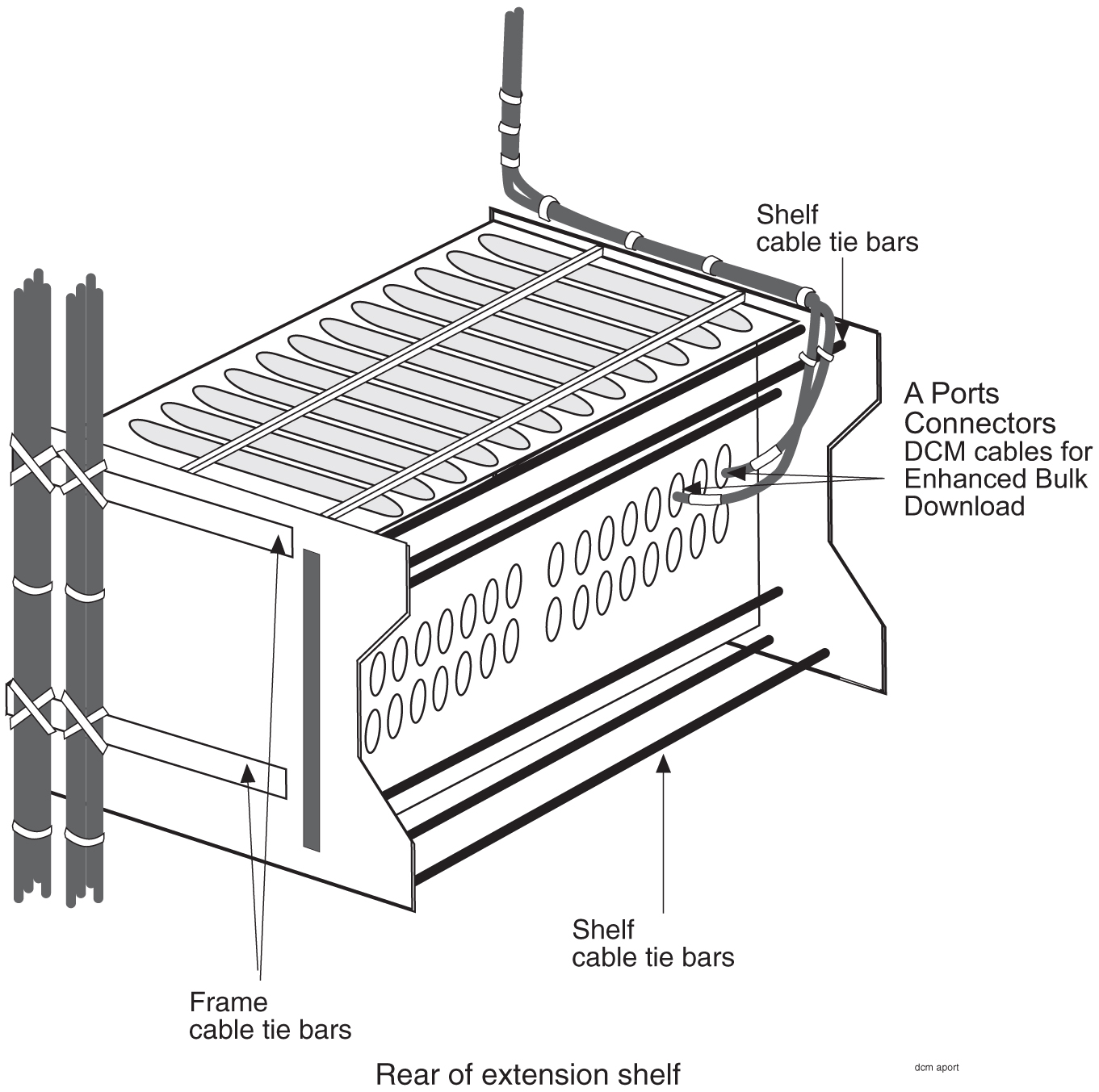
    Figure 6-9 Interface Cable Routing, Control Shelf


    img/t_dcm_and_fan_option_edcm_edcm_a_dsm_cabling_im-fig2.jpg

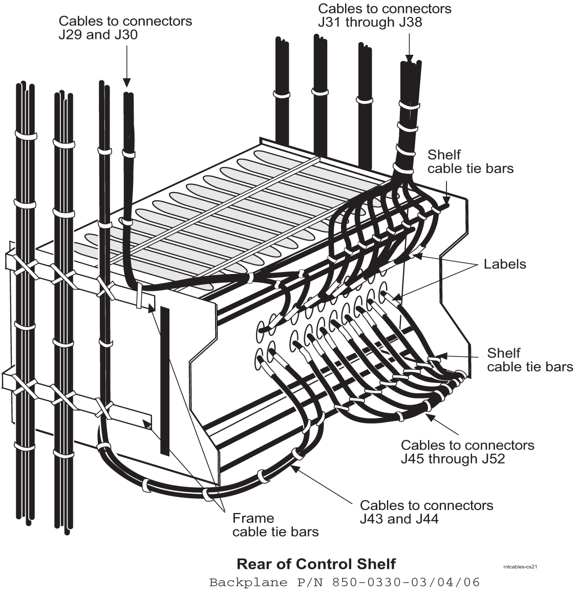
    Figure 6-10 Interface Cable Routing, Extension Shelf


    img/t_dcm_and_fan_option_edcm_edcm_a_dsm_cabling_im-fig3.jpg

6.3 User Upgrade Procedures

This section describes procedures for upgrading your ASM and TDM cards, and your DSM cards loaded with the MCPM application.

Note:

DSM and EDSM cards loaded with the MCPM application and the E5-MCPM-B card will be referred to as “MCPM cards.”

6.3.1 Upgrading to E5-MCPM-B Module (MCPM)

This procedure upgrades EDSM-2G cards with E5-MPCM-B cards. The optimal time of day to run the procedure is between xx35 and xx58 where xx is any value between 01 and 23. The stated times provide the best opportunity for minimal interference with normal collection and reporting operations.

Note:

Do not attempt this procedure during the first hour of the day (0000 to 0059).

Note:

Throughout this document, the term MCPM refers to both the E5-MCPM-B (P/N 870-3089-xx) and the EDSM-2G loaded with the MCPM application (P/N 870-2372-03) cards unless specifically noted otherwise.

The Primary MCPM card performs all measurements collection and reporting functions and provides on-card RAM storage for collected data and scheduled reports. The Secondary MCPM provides a redundant backup for the Primary module, and assumes collection and reporting responsibilities on the loss of the Primary. TCP/IP connections are used to deliver measurement reports from the Primary MCPM card to the customer via an FTP client. The FTP configuration can be customized to support automatic transfer of scheduled reports from the client to the server.

  1. Enter the following command to determine the status and number of the MCPM cards.
    rept-stat-meas
    The following is an example of the possible output.
    
                                       PST     SST      AST
    MEAS SS                            OOS-MT  Fault    ----- 
        ALARM STATUS =         ** 0516  MEAS degraded with card out of service 
    CARD        VERSION        TYPE    PST     SST      AST
    1107        P 101-9-000    MCPM    IS-NR   Active   ----- 
        IP LInk A                      IS-NR   Active   Available 
    1109        101-9-000      MCPM    OOS-MT  Fault    ----- 
        IP Link A                      OOS-MT  Fault    Unavailable 
    CARD 1107 ALARM STATUS = No Alarms 
    CARD 1109 ALARM STATUS = Card is isolated from the system
    Command Completed.
    ;
  2. Verify the location of the primary and secondary MCPM.
    The primary is noted by the P beside the card location in the output of rept-stat-meas.

    Note:

    The secondary MCPM should be upgraded before the primary MCPM.
  3. Enter the following command to remove the secondary MCPM card from service.
    • If there is more than one MCPM card in service, enter:

      inh-card:loc=xxxx

    • If there is only one MCPM card in service, enter:

      inh-card:loc=xxx:force=yes

      where xxxx is the secondary MCPM card location.

    Do not use the force command unless this is the only MCPM card in service; MCPM collection and reporting service should be maintained at all times.

    Note:

    Removing the last MCPM or only MCPM from service will cause loss of measurements data.
  4. Remove the secondary MCPM card.

    See Removing a Card in an Existing EAGLE System for removal procedures.

    1. Place the removed MCPM card into an ESD container.

      Note:

      Do not put it into the spare card storage shelf.
    2. Place the new MCPM (E5-MCPM-B) card into its place.
    3. Be sure the revision numbers of the card is compatible with the EAGLE software release.
      • If they are not, go to 5 to flash the card to the software release level of the EAGLE system.
      • If your card is compatible with the EAGLE software relelease level, go to 7.
      • If in doubt about the compatibility of your new hardware, call the My Oracle Support (MOS).
  5. Enter the following command to flash the card:
    init-flash:loc=xxxx:code=appr

    where xxxx is the location of the card.

    The following is sample output.
     
    rlghncxa03w 01-03-02 13:05:05 EST Rel 44.0
    FLASH Memory Downloading for card 1105 Started.
    rlghncxa03w 01-03-02 13:05:05 EST Rel 44.0
    BLMCAP Downloading for card 1105 Complete.
    rlghncxa03w 01-03-02 13:05:05 EST Rel 44.0
    Command Completed.
    ;
  6. Enter the following command to activate the FLASHGPL on the card:
    act-flash:loc=xxxx

    where xxxx is the location of the card.

    The following is sample output:
    
    rlghncxa03w 04-02-04 13:05:05 EST EAGLE 44.0
    FLASH Memory Activation for card 1105 Started.
    ;
    rlghncxa03w 04-02-04 13:05:05 EST EAGLE 44.0
    FLASH Memory Activation for card 1105 Completed.
    ;
    rlghncxa03w 04-02-04 13:05:05 EST EAGLE 44.0
    Command Completed.
    ;
  7. Enter the following command to return the upgraded MCPM card into service.
    alw-card:loc=xxxx

    where xxxx is the MCPM card location.

    • This causes the MASP to begin downloading tables to the new MCPM card.
    • When the card has been successfully loaded there will be a response on the terminal that downloading is complete.
    • This can take up to 10 minutes.
  8. Enter the following command to verify the card is operational (IS-NR).
    rept-stat-meas
  9. If you want to upgrade a spare MCPM, go to 10.

    Otherwise, got to 18.

  10. Remove the spare MCPM card from the spare card storage shelf.
  11. Place it into an ESD container.
  12. Enter the following command to remove the previously upgraded secondary MCPM card from service.
    • If there is more than one MCPM card in service, enter:

      inh-card:loc=xxxx
    • If there is only one MCPM card in service, enter:

      inh-card:loc=xxx:force=yes

      where xxxx is the secondary MCPM card location.

    This card will become the spare.

    Do not use the force command unless this is the only MCPM card in service; MCPM collection and reporting service should be maintained at all times.

    Note:

    Removing the last MCPM or only MCPM from service will cause loss of measurements data.
  13. Remove the MCPM card.

    See Removing a Card in an Existing EAGLE System for removal procedures.

    1. Place the removed MCPM card into the spare card storage shelf.
    2. Place the new MCPM (E5-MCPM-B) card into its place.
    3. Be sure the revision numbers of the card is compatible with the EAGLE software release.
      • If they are not, go to 14 to flash the card to the software release level of the EAGLE system.
      • If your card is compatible with the EAGLE software release level, go to 16.
      • If in doubt about the compatibility of your new hardware, call the My Oracle Support (MOS).
  14. Enter the following command to flash the card:
    init-flash:loc=xxxx:code=appr

    where xxxx is the location of the card.

    The following is sample output.
    
    rlghncxa03w 01-03-02 13:05:05 EST Rel 44.0 
    FLASH Memory Downloading for card 1105 Started.
    rlghncxa03w 01-03-02 13:05:05 EST Rel 44.0
    BLMCAP Downloading for card 1105 Complete.
    rlghncxa03w 01-03-02 13:05:05 EST Rel 44.0
    Command Completed.
    ;
  15. Enter the following command to activate the FLASH GPL on the card:
    act-flash:loc=xxxx

    where xxxx is the location of the card.

    The following is sample output:
    
    rlghncxa03w 04-02-04 13:05:05 EST EAGLE 44.0
    FLASH Memory Activation for card 1105 Started.
    ;
    rlghncxa03w 04-02-04 13:05:05 EST EAGLE 44.0
    FLASH Memory Activation for card 1105 Completed.
    ;
    rlghncxa03w 04-02-04 13:05:05 EST EAGLE 44.0
    Command Completed.
    ;
  16. Enter the following command to return the upgraded MCPM card into service.
    .alw-card:loc=xxxx

    where xxxx is the MCPM card location.

    • This causes the MASP to begin downloading tables to the new MCPM card.

    • When the card has been successfully loaded (there will be a response on the terminal that downloading is complete.

    • This can take up to 10 minutes.

  17. Enter the following command to verify the card is operational (IS-NR).
    rept-stat-meas
  18. Enter the following command to remove the primary MCPM card from service.
    • If there is more than one MCPM card in service, enter:

      inh-card:loc=xxxx
    • If there is only one MCPM card in service, enter:

      inh-card:loc=xxx:force=yes

      where xxxx is the primary MCPM card location.

    Do not use the force command unless this is the only MCPM card in service; MCPM collection and reporting service should be maintained at all times.

    Note:

    Removing the last MCPM or only MCPM from service will cause loss of measurements data.
  19. Remove the MCPM card.

    See Removing a Card in an Existing EAGLE System for removal procedures.

    1. Place the removed MCPM card into an ESD container.

      Note:

      Do not put it into the spare card storage shelf.
    2. Place the new MCPM (E5-MCPM-B) card into its place.
    3. Be sure the revision numbers of the card is compatible with the EAGLE software release.
      • If they are not, go to 20 to flash the card to the software release level of the EAGLE system.
      • If your card is compatible with the EAGLE software release level, go to 22.
      • If in doubt about the compatibility of your new hardware, call the My Oracle Support (MOS).
  20. Enter the following command to flash the card:
    init-flash:loc=xxxx:code=appr

    where xxxx is the location of the card.

    The following is sample output.
    
    rlghncxa03w 01-03-02 13:05:05 EST Rel 44.0
    FLASH Memory Downloading for card 1105 Started.
    rlghncxa03w 01-03-02 13:05:05 EST Rel 44.0
    BLMCAP Downloading for card 1105 Complete.
    rlghncxa03w 01-03-02 13:05:05 EST Rel 44.0
    Command Completed.
    ;
    
  21. Enter the following command to activate the FLASHGPL on the card:
    act-flash:loc=xxxx

    where xxxx is the location of the card.

    The following is sample output:
    
    rlghncxa03w 04-02-04 13:05:05 EST EAGLE 44.0
    FLASH Memory Activation for card 1105 Started.
    ;
    rlghncxa03w 04-02-04 13:05:05 EST EAGLE 44.0
    FLASH Memory Activation for card 1105 Completed.
    ;
    rlghncxa03w 04-02-04 13:05:05 EST EAGLE 44.0
    Command Completed.
    ;
    
  22. Enter the following command to return the upgraded MCPM card into service.
    alw-card:loc=xxxx

    where xxxx is the MCPM card location.

    • This causes the MASP to begin downloading tables to the new MCPM card.

    • When the card has been successfully loaded (there will be a response on the terminal that downloading is complete.

    • This can take up to 10 minutes.

      Note:

      Ensure that the primary FTP server points to the primary card.
  23. Enter the following command on the primary card to return the card to the status recorded in 1 prior to the upgrade:
    init-card:loc=xxxx

    where xxxx is the location of the primary card.

  24. Enter the following command to verify the card is operational (IS-NR).
    rept-stat-meas

6.3.2 Measurement Collection and Polling Module (MCPM)

This procedure upgrades DSM cards loaded with the MCPM application (870-2371-03) to EDSM cards with 32 MBFSRAM and 2 GBRAM loaded with the MCPM application (870-2372-03).

Note:

DSM and EDSM cards loaded with the MCPM application will be referred to as “MCPM cards.”

The Primary MCPM card performs all measurements collection and reporting functions and provides on-card RAM storage for collected data and scheduled reports. The Secondary MCPM provides a redundant backup for the Primary module, and assumes collection and reporting responsibilities on the loss of the Primary. TCP/IP connections are used to deliver measurement reports from the Primary MCPM card to the customer via an FTP client. The FTP configuration can be customized to support automatic transfer of scheduled reports from the client to the server.

  1. Enter the following command to determine the status and number of the MCPM cards.
    rept-stat-meas
    The following is an example of the possible output.
    
                                       PST     SST      AST
    MEAS SS                            OOS-MT  Fault    ----- 
        ALARM STATUS =         ** 0516  MEAS degraded with card out of service 
    CARD        VERSION        TYPE    PST     SST      AST
    1107        P 101-9-000    MCPM    IS-NR   Active   ----- 
        IP LInk A                      IS-NR   Active   Available 
    1109        101-9-000      MCPM    OOS-MT  Fault    ----- 
        IP Link A                      OOS-MT  Fault    Unavailable 
    CARD 1107 ALARM STATUS = No Alarms 
    CARD 1109 ALARM STATUS = Card is isolated from the system
    Command Completed.
    ;
    
    
  2. Verify the location of the primary and secondary MCPM.
    The primary is noted by the P beside the location in the output of rept-stat-meas. Upgrade the secondary MCPM first.
  3. Enter the following command to remove the secondary MCPM card from service.
    Do not use the force command unless this is the only MCPM card in service; MCPM collection and reporting service should be maintained at all times.

    Note:

    Removing the last MCPM or only MCPM from service will cause loss of measurements data.
    If there is more than one MCPM card in service, enter:
    inh-card:loc=xxxx
    where xxxx is the secondary MCPM card location.
    If there is only one MCPM card in service, enter:
    inh-card:loc=xxx:force=yes
    where xxxx is the secondary MCPM card location.
  4. Remove the MCPM card.
    See Removing a Card in an Existing EAGLE System for removal procedures. Place the removed MCPM card into an ESD container; do not put it into the spare card storage shelf. Place the new MCPM (EDSM) card into its place. Be sure the revision numbers of the card is compatible with the EAGLE software release. If they are not, go to 5 to flash the card to the software release level of the EAGLE system. If your card is compatible with the EAGLE software release level, go to 7 . If in doubt about the compatibility of your new hardware, call the My Oracle Support (MOS).
  5. Enter the following command to flash the card:
    init-flash:loc=xxxx:code=appr
    Where xxxx is the location of the card.
    The following is sample output.
    
     
    rlghncxa03w 01-03-02 13:05:05 EST Rel 28.1.0
    FLASH Memory Downloading for card 1105 Started.
    rlghncxa03w 01-03-02 13:05:05 EST Rel 28.1.0
    BPDCM Downloading for card 1105 Complete.
    rlghncxa03w 01-03-02 13:05:05 EST Rel 28.1.0
    Command Completed.
    ;
    
    
  6. Enter the following command to activate the FLASHGPL on the card:
    act-flash:loc=xxxx
    Where xxxx is the location of the card.
    The following is sample output:
    
    rlghncxa03w 04-02-04 13:05:05 EST EAGLE 31.3.0
    FLASH Memory Activation for card 1105 Started.
    ;
    rlghncxa03w 04-02-04 13:05:05 EST EAGLE 31.3.0
    FLASH Memory Activation for card 1105 Completed.
    ;
    rlghncxa03w 04-02-04 13:05:05 EST EAGLE 31.3.0
    Command Completed.
    ;
    
  7. Enter the following command to return the upgraded MCPM card into service.
    This causes the MASP to begin downloading tables to the new MCPM card.
    alw-card:loc=xxxx
    Where xxxx is the MCPM card location.
    When the card has been successfully loaded (there will be a response on the terminal that downloading is complete).
    This can take up to 10 minutes.
  8. Enter the following command to verify the card is operational (IS-NR).
    rept-stat-measIf the secondary MCPM card is operational, go to 9 . If it is not, call the My Oracle Support (MOS).
  9. If you want to upgrade a spare MCPM, go to 10 .
    Otherwise, got to 16 .
  10. Remove the spare MCPM card from the spare card storage shelf and place it into an ESD container.
    Next, enter the following command to remove the previously upgraded secondary MCPM card from service. This card will become the spare. Do not use the force command unless this is the only MCPM card in service; MCPM collection and reporting service should be maintained at all times.

    Note:

    Removing the last MCPM or only MCPM from service will cause loss of measurements data.
    If there is more than one MCPM card in service, enter:
    inh-card:loc=xxxx
    where xxxx is the secondary MCPM card location.
    If there is only one MCPM card in service, enter:
    inh-card:loc=xxx:force=yes
    where xxxx is the secondary MCPM card location.
  11. Remove the MCPM card.
    See Removing a Card in an Existing EAGLE System for removal procedures. Place the removed MCPM card into the spare card storage shelf. Place the new MCPM (EDSM) card into its place. Be sure the revision numbers of the card is compatible with the EAGLE software release. If they are not, go to 12 to flash the card to the software release level of the EAGLE system. If your card is compatible with the EAGLE software release level, go to 14 . If in doubt about the compatibility of your new hardware, call the My Oracle Support (MOS).
  12. Enter the following command to flash the card:
    init-flash:loc=xxxx:code=appr
    Where xxxx is the location of the card.
    The following is sample output.
    
    rlghncxa03w 01-03-02 13:05:05 EST Rel 28.1.0 
    FLASH Memory Downloading for card 1105 Started.
    rlghncxa03w 01-03-02 13:05:05 EST Rel 28.1.0
    BPDCM Downloading for card 1105 Complete.
    rlghncxa03w 01-03-02 13:05:05 EST Rel 28.1.0
    Command Completed.
    ;
    
  13. Enter the following command to activate the FLASHGPL on the card:
    act-flash:loc=xxxx
    Where xxxx is the location of the card.
    The following is sample output:
    
    rlghncxa03w 04-02-04 13:05:05 EST EAGLE 31.3.0
    FLASH Memory Activation for card 1105 Started.
    ;
    rlghncxa03w 04-02-04 13:05:05 EST EAGLE 31.3.0
    FLASH Memory Activation for card 1105 Completed.
    ;
    rlghncxa03w 04-02-04 13:05:05 EST EAGLE 31.3.0
    Command Completed.
    ;
    
  14. Enter the following command to return the upgraded MCPM card into service.

    This causes the MASP to begin downloading tables to the new MCPM card

    .alw-card:loc=xxxx
    Where xxxx is the MCPM card location.
    When the card has been successfully loaded (there will be a response on the terminal that downloading is complete). This can take up to 10 minutes.
  15. Enter the following command to verify the card is operational (IS-NR).
    rept-stat-measIf the secondary MCPM card is operational, go to 16. If it is not, call the My Oracle Support (MOS).
  16. Enter the following command to remove the primary MCPM card from service.
    Do not use the force command unless this is the only MCPM card in service; MCPM collection and reporting service should be maintained at all times.

    Note:

    Removing the last MCPM or only MCPM from service will cause loss of measurements data.
    If there is more than one MCPM card in service, enter:
    inh-card:loc=xxxx
    where xxxx is the primary MCPM card location.
    If there is only one MCPM card in service, enter:
    inh-card:loc=xxx:force=yes
    where xxxx is the primary MCPM card location.
  17. Remove the MCPM card.
    See Removing a Card in an Existing EAGLE System for removal procedures. Place the removed MCPM card into an ESD container; do not put it into the spare card storage shelf. Place the new MCPM (EDSM) card into its place. Be sure the revision numbers of the cards are compatible with the EAGLE software release. If they are not compatible, you should go to 18 to flash the card to the software release level of the EAGLE system. If your card is compatible with the EAGLE software release level, proceed to 20. If in doubt about the compatibility of your new hardware, call the My Oracle Support (MOS).
  18. Enter the following command to flash the card:
    init-flash:loc=xxxx:code=appr
    Where xxxx is the location of the card.
    The following is sample output.
    
    rlghncxa03w 01-03-02 13:05:05 EST Rel 28.1.0
    FLASH Memory Downloading for card 1105 Started.
    rlghncxa03w 01-03-02 13:05:05 EST Rel 28.1.0
    BPDCM Downloading for card 1105 Complete.
    rlghncxa03w 01-03-02 13:05:05 EST Rel 28.1.0
    Command Completed.
    ;
    
  19. Enter the following command to activate the FLASHGPL on the card:
    act-flash:loc=xxxx
    Where xxxx is the location of the card.
    The following is sample output:
    
    rlghncxa03w 04-02-04 13:05:05 EST EAGLE 31.3.0
    FLASH Memory Activation for card 1105 Started.
    ;
    rlghncxa03w 04-02-04 13:05:05 EST EAGLE 31.3.0
    FLASH Memory Activation for card 1105 Completed.
    ;
    rlghncxa03w 04-02-04 13:05:05 EST EAGLE 31.3.0
    Command Completed.
    ;
    
  20. Enter the following command to return the upgraded MCPM card into service.
    This causes the MASP to begin downloading tables to the new MCPM card.
    alw-card:loc=xxxx
    Where xxxx is the MCPM card location.
    When the card has been successfully loaded (there will be a response on the terminal that downloading is complete). This can take up to 10 minutes.

    Note:

    Ensure that the primary FTP server points to the primary card.
  21. Enter the following command on the primary card to return the card to the status recorded in 1 prior to the upgrade:
    init-card:loc=xxxx
    where xxxx is the location of the primary card.
  22. Enter the following command to verify the card is operational (IS-NR).
    rept-stat-meas

6.3.3 Removing a Card in an Existing EAGLE System

Use this procedure anytime a card is removed from a previously operational EAGLE system for upgrade purposes. See Maintenance Guide for card replacement. Failure to use this procedure may result in equipment damage. Use the procedures at the beginning of this section before physically removing any cards.

attention:

Before performing any maintenance procedures on the EAGLE, make sure you wear a wrist strap connected to the wrist strap grounding point of the EAGLE System.

Before removing, reseating, or initializing a card, inhibit any OAP terminal ports that are in-service normal (IS-NR) to ensure the card loads properly. No database updates or single command line entries should be made while the card is loading.

attention:

This procedure may interrupt service. When possible, perform maintenance during low traffic and database provisioning periods, such as the maintenance window.
  1. Locate the card to be removed.

    Note:

    To ensure no loss of service, be sure to check that the green LED on the card is not lit when you remove the card.
  2. Push the inject/eject clamps outward from the card’s faceplate (top clamp in the “UP” position, bottom clamp in the “DOWN” position). Pull the levers away from the shelf until they are parallel to the floor.
    Gently pull the card towards you until the card clears the shelf.

    Figure 6-11 Push Inject/Eject Clamps Outward

    img/t_removing_a_card_in_an_existing_eagle_5_iss_system_im-fig1.jpg
  3. Place the card you have removed in an electrostatic discharge (ESD) protective container, or place the card in the spare card storage shelf.
  4. Be sure that the replacement card has the same part number and revision number as the card you have just removed (unless this is an upgrade).
  5. Open the ejector levers on the replacement card.
    Carefully align the card’s edges with the top and bottom card guides. Then push the card along the length of the card guides until the rear connectors on the card engage the mating connectors on the target shelf backplane.
  6. Press the front of the card’s faceplate using constant pressure until you feel the card’s progress cease.

    attention:

    Do not impact the faceplate in order to mate the connectors. Any impact to the card’s faceplate can damage the faceplate, the pins, or the connectors.
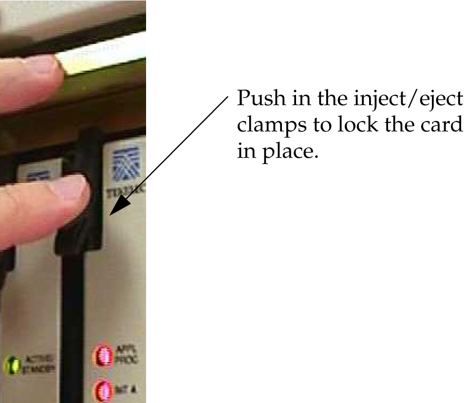
  7. Push in the top and bottom inject/eject clamps.
    This locks the card in place and ensures a strong connection with the pins on the target shelf backplane.

    Figure 6-12 Push in Inject/Eject Clamps

    img/t_removing_a_card_in_an_existing_eagle_5_iss_system_im-fig2.jpg
  8. Verify that both IMT bus LEDs are green.
  9. Record the activity in the site maintenance log.

6.4 Fan Assembly Installation and Cabling

warning:

Do not carry exposed metal keys or tools in pockets or on belts when working on or around system equipment.

warning:

Do not wear metal rings, watches, or jewelry on wrists or hands when working on system equipment or other related electrostatic sensitive components. Always wear a wrist strap or other electrostatic protection when handling printed circuit cards and other electrostatic sensitive devices.

Caution:

Be sure to install the fan assembly 890-0001-04 before installing the HCMIM card.

This section shows how to install the optional Fan Assembly 890-0001-04 and Fan Assembly 890-1038-01/890-1038-02. All of these fan assemblies can be installed in the standard frame and the Heavy Duty Frame. Be sure to determine which type of frame you have before performing these procedures.

6.4.1 Installing Fan Assembly 890-0001-04

Note:

Beginning with EAGLE software release 33.0, all systems with HCMIM cards must have the 890-0001-04 fan assembly installed.

Tools needed:

  • #1 Flat screwdriver

  • #2 Philips screwdriver (long)

  • Fiber Paper (Approximately 2’ x 3’)

  • 5/16” ratchet socket wrench

  • Tie Wraps

Procedure — Install and Retrofitting Fans

  1. Determine which shelves will have HCMIM modules installed and be aware of hardware that needs to be retained or installed in a specific way.

  2. Place a piece of fiber paper on the top of the shelf below where the fan is to be installed to ensure that nothing will drop into equipment below the new fan.

  3. Make sure to pull both dummy fuses from the appropriate fuse locations for the A and B fan power. Use the following guidelines to determine fuse locations:

    • The fuse card located on the Fuse and Alarm Panel is marked FAN A and FAN B. Fuse positions 6, 12, and 18 are the correct locations on the FAP faceplate.

    • Fuse position 6 is for the fan unit directly below the x100 shelf.

    • Fuse position 12 is for the fan directly below the x200 shelf.

    • Fuse position 18 is for the fan directly below the x300 shelf.

    • All fans are to be fused at 3As, with blue flags, per feed. Fill out the fuse card completely.

    • Ensure the FAP fuse location for the fan is properly labeled.

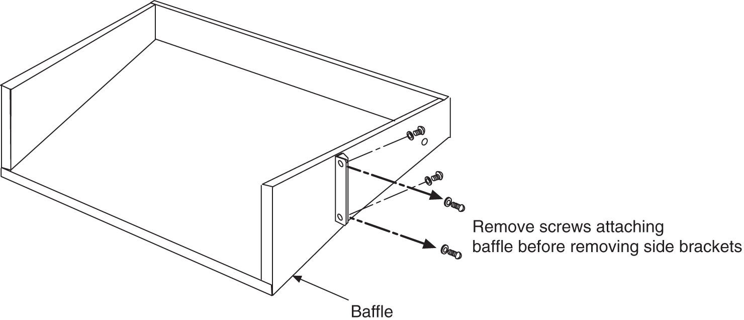
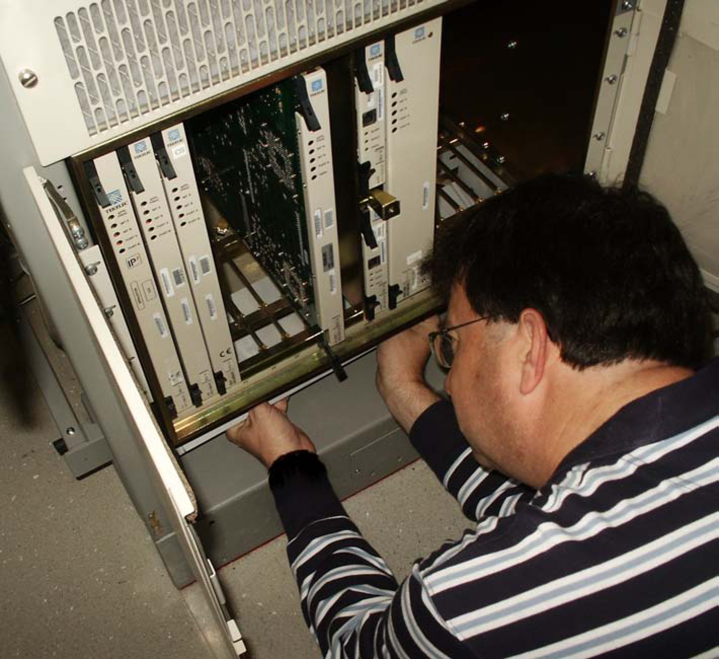
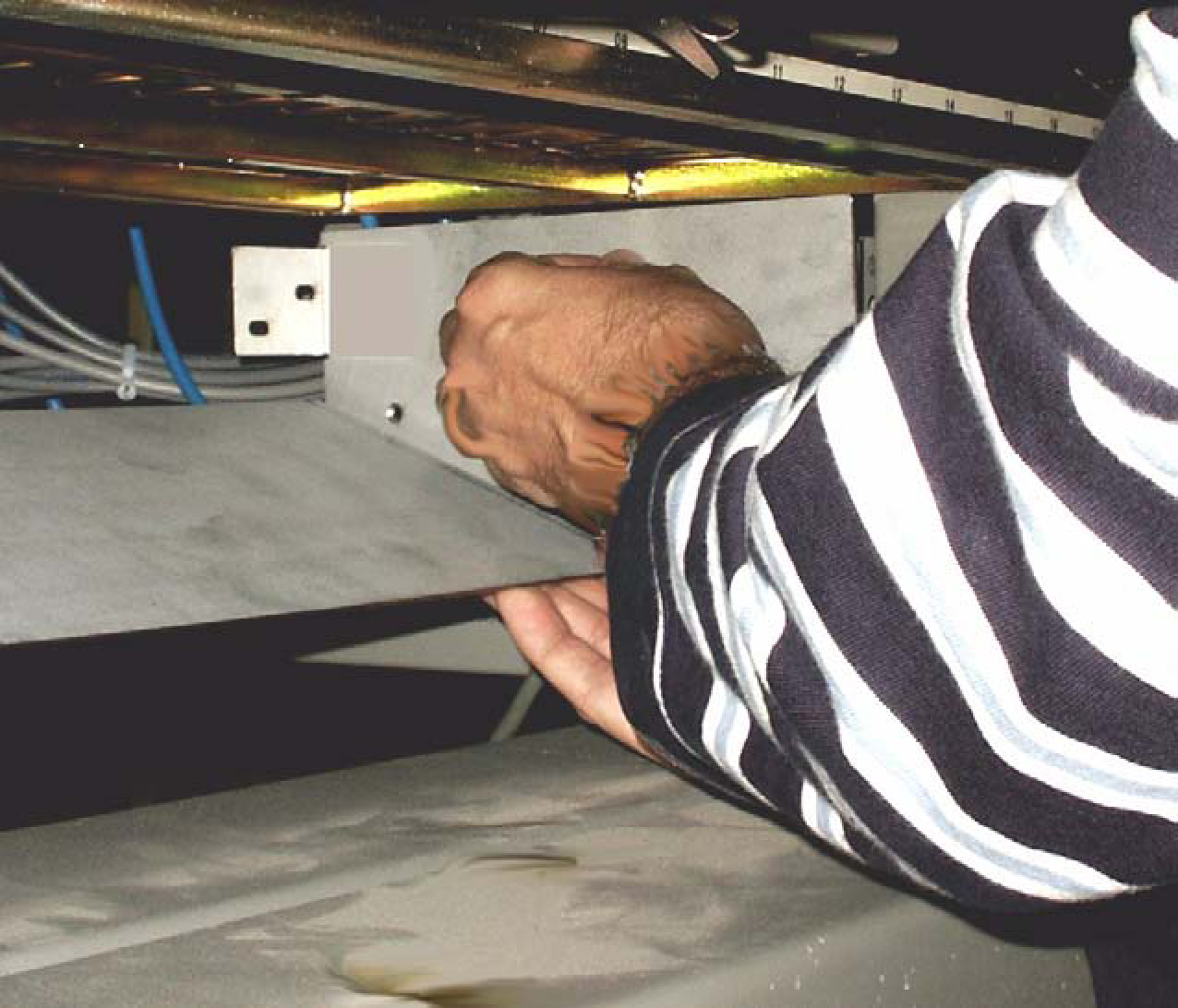
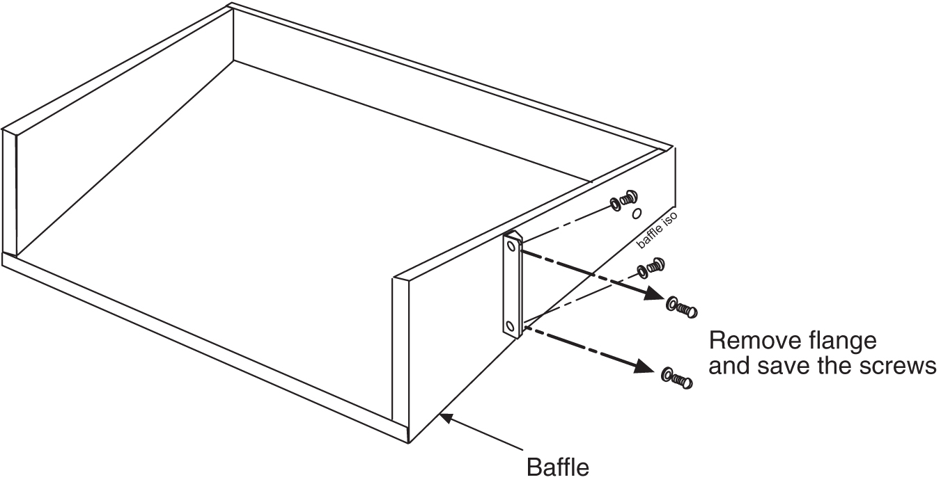
  4. If you are installing the fan assembly into an existing frame, remove the four screws (two on each side) that attach the air baffle to the mounting brackets. Do not remove the screws holding the side brackets to the frame at this time. Support the baffle while you remove the screws.

    Figure 6-13 System Air Baffle


    img/c_installing_fan_assembly_890000104_im-fig1.jpg

  5. Remove the baffle through the front of the frame. Then, remove the two screws holding the left and right side baffle brackets to the frame and remove the brackets.

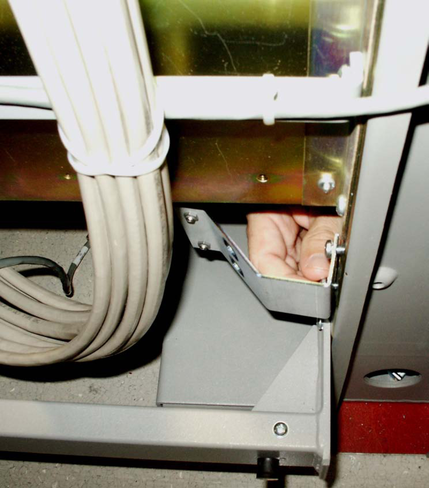
  6. Install the new side brackets for the new fan tray into the frame. The side brackets are installed from the front of the frame just below the shelf containing that cards that require the fan. Use the 12-24-x1/2 screws provided to attach the brackets to the left and right front frame rails. The top screw hole is 5/16 inch below the shelf containing the cards. Be sure not to completely tighten the brackets at this time.

    Figure 6-14 Attach side fan bracket to front frame rail


    img/c_installing_fan_assembly_890000104_im-fig2.jpg

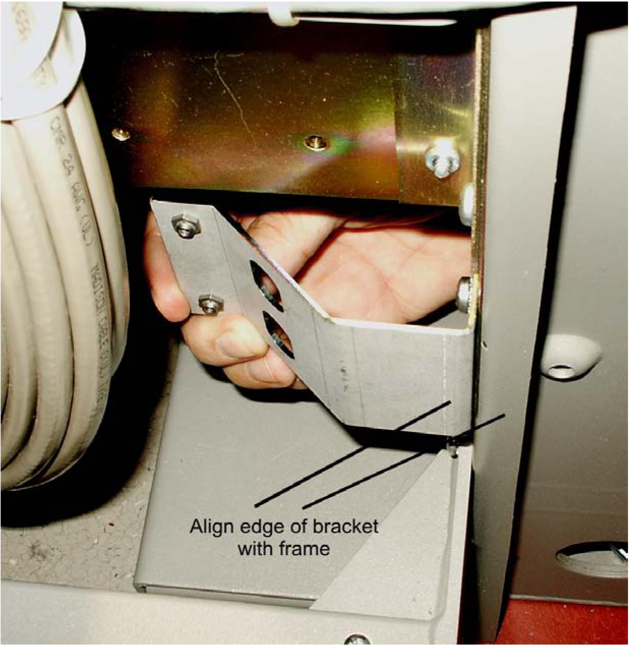
  7. Slide the brackets in toward the center of the frame so the outside of the bracket is flush with the side of the frame as shown in Figure 6-15.

    Figure 6-15 Slide the side fan brackets flush with the Frame


    img/c_installing_fan_assembly_890000104_im-fig3.jpg

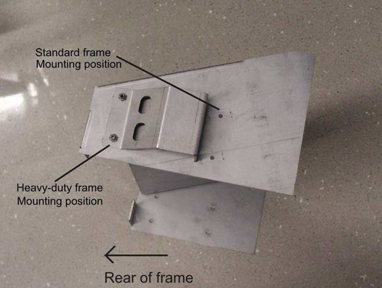
  8. Verify whether the frame type is a standard or heavy duty so that you can ensure the fan tray bracket will be mounted correctly. Use the following mounting positions:

    • Use the side holes on the fan tray bracket that are closest to the front of the frame if you are installing in a standard frame.

    • Use the holes closest to the rear of the frame if installing in a heavy duty frame.

      Figure 6-16 Side bracket mounting positions on fan tray bracket.


      img/c_installing_fan_assembly_890000104_im-fig4.jpg

  9. Insert the fan tray bracket (P/N 652-0012-01) into the space left by the baffle under the card shelf. The untightened side brackets will slide outward slightly to accommodate the fan tray bracket as it is inserted. They should remain flush against the fan tray bracket.

    Figure 6-17 Insert fan tray bracket


    img/c_installing_fan_assembly_890000104_im-fig5.jpg

    Note:

    When inserting the fan tray bracket, be sure not to pinch cables between the bottom of the shelf and the fan tray bracket.
  10. From inside the frame, screw the fan tray bracket to the side brackets with one hand while using the other hand to support the fan tray bracket. Use two 8-32 phillips screws for each side bracket. See Figure 6-18.

    Figure 6-18 Attaching the fan tray bracket to the side brackets - inside front


    img/c_installing_fan_assembly_890000104_im-fig6.jpg

  11. Remove the new fan tray from the container. The fan tray is shipped with the three fans already installed.

    Figure 6-19 Fan Tray


    img/c_installing_fan_assembly_890000104_im-fig7.jpg
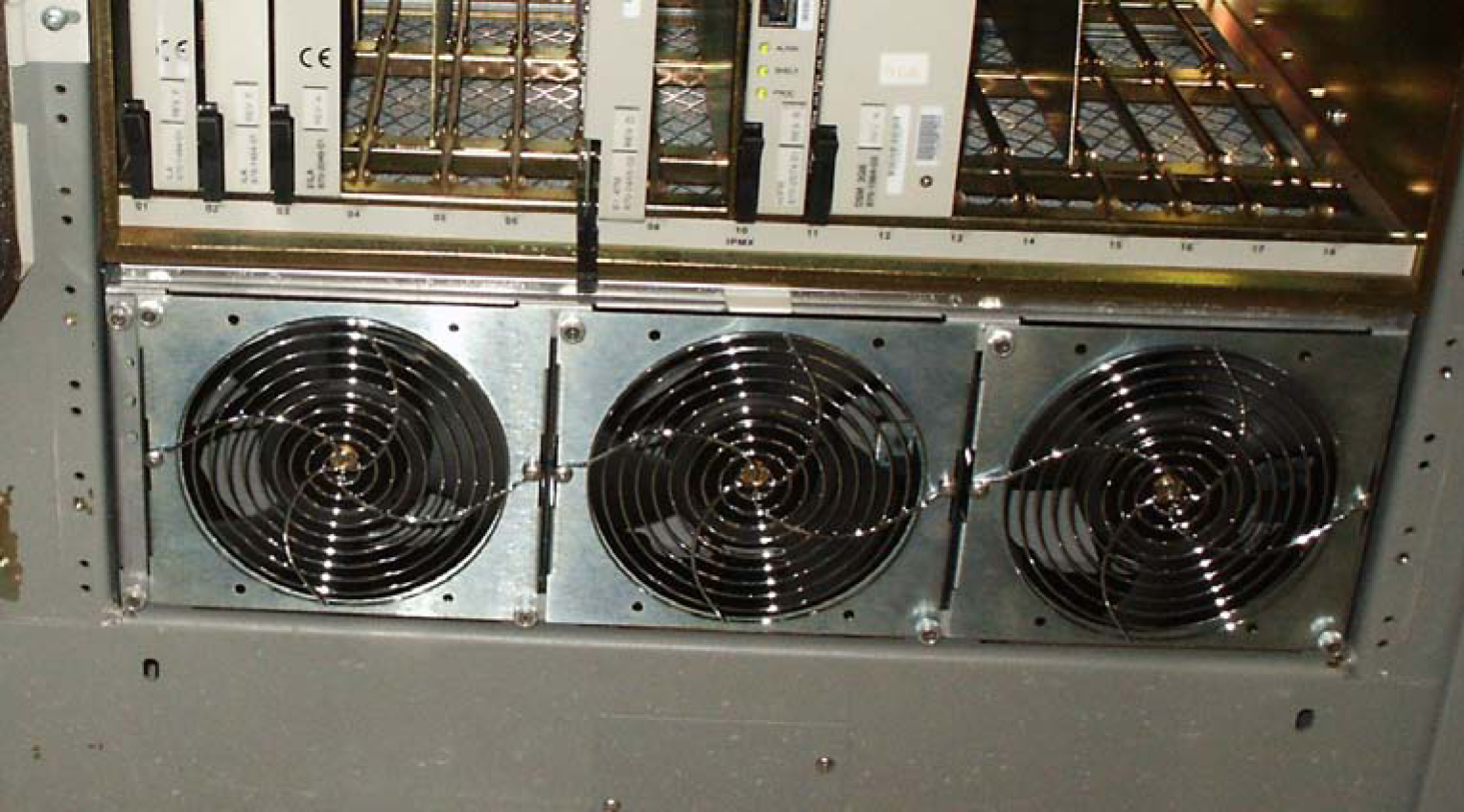
  12. Insert the fan tray into the fan tray bracket. You might need to tilt the fan tray up as it is pushed in so that it is completely inserted into the bracket. After insertion, be sure the front of the fan tray is recessed in 1/2 inch with respect to the front frame rails.

    Figure 6-20 Fan tray inserted into fan tray bracket in the frame- front view


    img/c_installing_fan_assembly_890000104_im-fig8.jpg

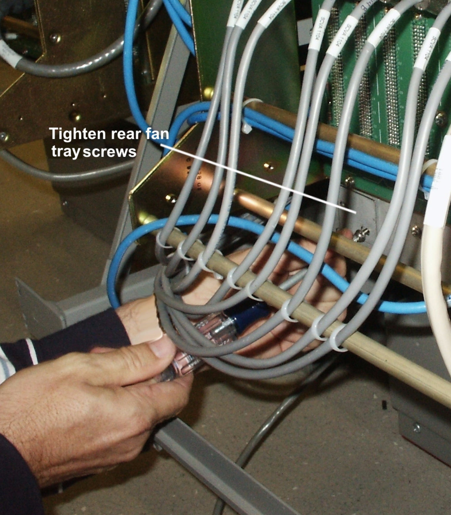
  13. When the fan tray is aligned and in place, attach the fan tray to the fan tray bracket by tightening the screws on the left and right sides of the rear of the fan tray bracket. There are two screws on each side. These screws must be tightened from the rear of the frame.

    Figure 6-21 Tighten rear fan tray screws


    img/c_installing_fan_assembly_890000104_im-fig9.jpg

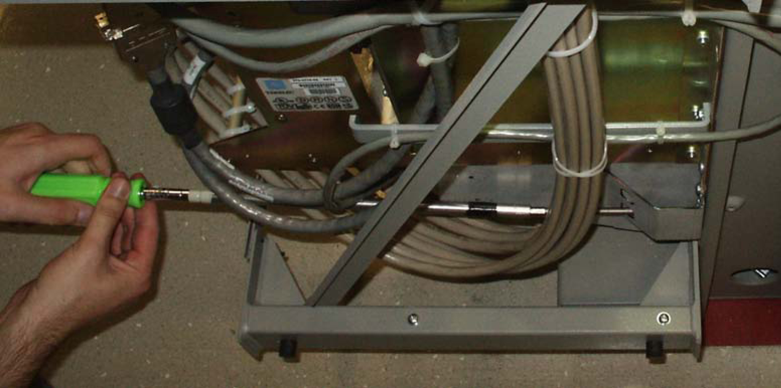
  14. At this time check and tighten all screws, including the screws holding the side brackets to the frame. The side bracket screws should be tightened fully from the rear of the frame. Use a long hex driver or flat head screw driver.

    Figure 6-22 Tighten fan side bracket screws


    img/c_installing_fan_assembly_890000104_im-fig10.jpg

  15. Remove the piece of fiber paper on the top of the shelf below where the fan assembly was installed. This procedure is complete.

    Caution:

    Before powering up the fans, ensure that the shelf directly above the fan does not contain any empty slots. Install an air management card in any empty slots to ensure proper air flow. These filler cards have no electrical connection to the system. See Card Installation and Replacement for general card installation guidelines.

6.4.2 Installing Fan Cables

On the control and extension shelf backplanes, the connectors are marked A FAN POWER and B FAN POWER.

  • Control shelf:

    On backplane (P/N 850-0330-06 or -07) the connectors are A FAN POWER, J-9 and B FAN POWER, J-8.

    These connectors are located at the upper middle of the backplane on both the control shelf and the extension shelves.

  • Extension shelf: The backplane connectors are A, J-3 and B J-2.

  • For A fan power:

    The fan cable 830-1157-01 is included with the fan assembly. Plug one end of the cable into J-9 on the backplane. Route the cable to the left of the frame, faced from the rear, and to the assembly, to the connection marked FAN A POWER.

  • For B fan power:

    Plug one end of the cable 830-1157-01 into J-8 on the backplane. Route the cable to the right of the frame, faced from the rear, and to the fan assembly, to the connection marked FAN B POWER. Form and dress the two cables together and check the security of all of the connections.

  1. To cable the fan assembly, plug a cable onto the shelf on backplane FAN A POWER, and connector J9.
    Tighten the screws on the connector.
  2. When the cable is connected to the backplane route the cable to the top tie-down rod and secure the cable with a tie-wrap.
  3. Route the cable to the right side of the frame.
    Run the cable between the shelf and the traverse arms.

    Caution:

    Do not form the cable with the LIM cables.
  4. Secure the fan cables to the back side of the traverse arm using tie-wraps.
  5. Plug the other end of the cable onto the fan unit connector marked FAN A POWER.
    Tighten the screws on the connector.
  6. The other fan cable (P/N 830-0690-01) plugs into the backplane connector J8.
    Tighten the screws on the connector.
  7. Route the cable out to the top tie down rod and secure it using a tie-wrap.
    Run the cable down between the shelf and traverse arm.

    Caution:

    Do not form FAN POWER cables with LIM cables.
  8. Secure the cables to the back side of the traverse arms using tie-wraps.
  9. Plug the other end of the cable onto the fan unit connector marked FAN B POWER.
    Secure the connector.

6.4.3 Powering Up the Fan Assembly

All fans are fused at 3A (blue) per feed.

warning:

Before powering up the fans, ensure that the shelf above the fan does not contain any empty slots. Install the air management card in any empty slots. See Card Installation and Replacement for general card installation guidelines.

Procedure — Power up Fan Assembly

  1. After the fan is installed, the powering up process depends on the shelf location.
    • The fuse card located on the Fuse and Alarm Panel are marked FAN A and FAN B, fuse positions 6, 12, and 18 are marked correct locations on the FAP faceplate.
    • Fuse position 6 is for the fan unit directly below the x100 shelf.
    • Fuse position 12 is for the fan directly below the x200 shelf.
    • Fuse position 18 is for the fan directly below the x300 shelf.
    • All fans are to be fused at 3As, with blue flags, per feed.
    • Fill out the fuse card completely.
    • Ensure the FAP fuse location for the fan is properly labeled.

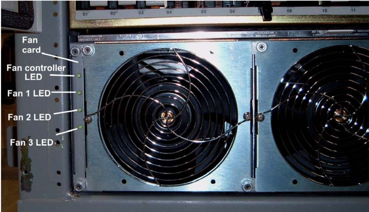
  2. Fifteen seconds after both the A side and B side power is connected to the fan assembly all of the LEDs on the fan controller card (located on the left side of the front of the fan assembly) are green.

    Figure 6-23 Fan card with LEDs on front of fan assembly


    img/t_powering_up_the_fan_assembly_im-fig1.jpg

  3. When the fans are powered up and running, a test must be conducted to ensure proper service.
    Go to the system terminal.
  4. Check to see if the fan feature is activated. At the terminal, enter the command:
    rtrv-feat

    If the fan feature is off, go to 5. Otherwise, go to 6.

  5. At the terminal, enter the command:
    chg-feat:fan=on

    Note:

    UAM 0080 will be raised for HC-MIM, E5-EPM-B or E5-SM8G-B if shelf FAN bit is OFF. These cards can be provisioned with ent-cardcommand. UAM 0080 will be cleared once shelf FAN bit is turned ON.

    With this command the user will perform the tests beginning with 7.

  6. At the terminal, enter the command:
    rept-stat-trbl

    Check to see that there are no fan errors. Specifically, check that there are no “#302 Cooling Fan Failure” errors. Next, perform the tests beginning with 6.

  7. Fan Verification (perform 7 through 12 for each fan assembly).
    Move to the rear of the frame and remove the A POWER cable from the FAN unit. Result: Fan 2 and Fan 3 LEDs will blink as the fans speed up to maximum speed. This may take up to 15 seconds. Once maximum speed has been reached Fan 2 and Fan 3 LEDs on the Fan Controller card will be solid green. Fan 1 LED should be red. The controller LED should be blinking green. Fan 1 should stop running and the MINORLED is lit.
  8. At the system terminal enter the command:
    rept-stat-trbl

    This step is repeated for each fan. Test each fan to ensure that the alarm and the units are working correctly. Result: The terminal reports:

    
    # 302 Cooling Fan Normal.
    
  9. Replace the A POWER cable on the back of the FAN unit and secure the connector.
    Result: All fans are running and the MINORLED is not lit.
    
    Terminal reports alarm:   # 303 Cooling Fan Normal
    .
    
  10. Remove the B POWER cable from the FAN unit.
    Result: Fan 1 and Fan 2 LEDs will blink as the fans speed up to maximum speed. This may take up to 15 seconds. Once maximum speed has been reached Fan 1 and Fan 2 LEDs will be solid green. Fan 3 LED should be red. The fan controller LED should be blinking. Fan 3 should stop running and the MINORLED is lit.
  11. At the system terminal enter the command:
    rept-stat-trbl

    Test each fan to ensure that the alarms and the unit is working correctly. Result: The terminal reports:

    
    # 302 Cooling Fan Normal.
    
  12. Replace the B POWER cable on the back of the FAN unit and secure the connector.
    Result: The fans are running and the MINORLED is not lit. The terminal reports alarm:
    
    # 303 Cooling Fan Normal.
    
  13. Repeat 7 through 12 for each fan unit installed.
    This procedure is complete.

6.4.4 Installing Fan Assembly 890-1038-01 or 890-1038-02

Tools needed:

  • #1 Flat screwdriver

  • #2 Philips screwdriver (long)

  • Fiber Paper (Approximately 2’ x 3’)

  • Tie Wraps

  1. Determine where the fan assembly will be installed and be aware of hardware that needs to be retained or installed in a specific way, see Figure 6-25.
  2. Place a piece of fiber paper on the top of the shelf below where the fan is to be installed, to ensure that nothing will drop into the area and equipment below.
    1. The fan unit is secured with the same screws that are removed from the frame holding the baffle in place.
    2. The brackets are installed from the rear of the frame using the screws provided with the brackets (standard frame).
    3. When the brackets are attached, secure them to the frame using external tooth washers and four screws.
  3. Remove the four screws, two on each side, from the mounting brackets on the frame that hold the baffle in place, on both sides.
    This will allow the removal of the baffle.

    Figure 6-24 System Air Baffle


    img/t_installing_fan_assembly_890103801_or_890103802_im-fig1.jpg

  4. Place the screws in a safe place because they are used later in this procedure.
  5. Remove the baffle through the front of the frame.
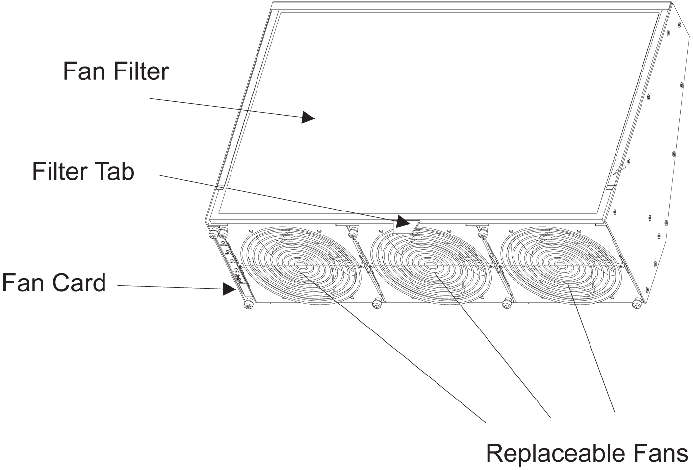
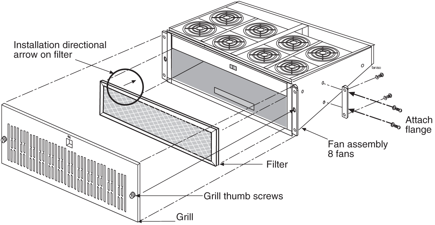
  6. Remove the fan unit from the container and remove the grill and filter from the unit assembly.
    The fan is shipped with the side flange not attached. Set the grill and filter in a safe location; it will be used later in this procedure.

    Figure 6-25 Fan Assembly with Grill and Filter


    img/t_installing_fan_assembly_890103801_or_890103802_im-fig2.jpg

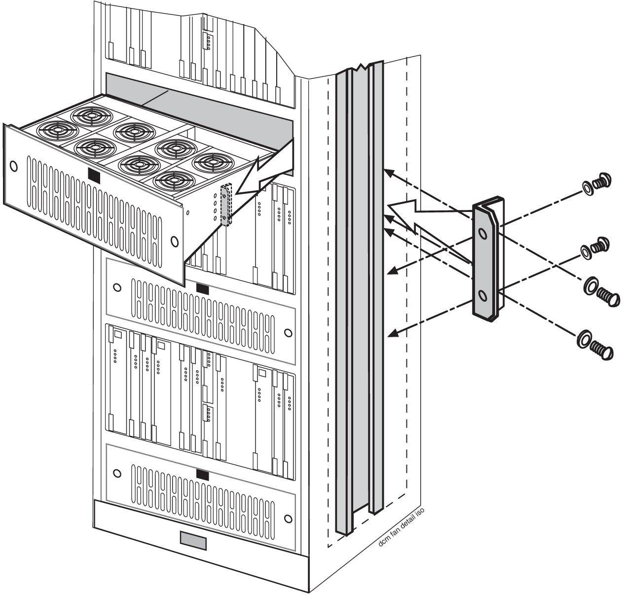
  7. Install the fan unit in the space left by the baffle.

    Figure 6-26 Installing Fan Assembly


    img/t_installing_fan_assembly_890103801_or_890103802_im-fig3.jpg

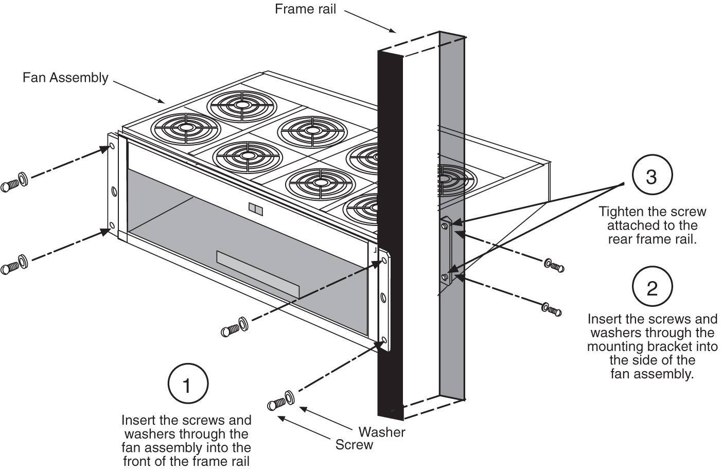
    Figure 6-27 Fan Bracket Installation


    img/t_installing_fan_assembly_890103801_or_890103802_im-fig4.jpg

  8. Secure the fan unit with the same screws that were removed from the frame holding the baffle in place.
    Do not tighten the screws at this time to allow for some minor adjustment. See Figure 6-27.

    Note:

    When mounting the fan unit, be sure not to pinch cables between the bottom of the shelf and the fan unit.
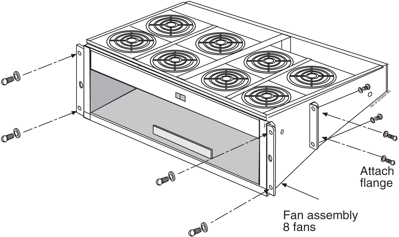
  9. From the front of the frame, install the four screws and tighten.
    At this time, check and tighten all screws

    Figure 6-28 Fan with Brackets and Screws


    img/t_installing_fan_assembly_890103801_or_890103802_im-fig5.jpg

  10. Return to the back of the frame and tighten the screws in the mounting brackets into the side of the fan unit.
  11. When the fan unit is aligned and in place, tighten the screws in the brackets on the sides of the frame.
  12. Reinstall the fan filter.
    The filter has an arrow stamped on the top edge to indicate the direction of the air flow. The arrow points toward the fans.
  13. Install the fan grill, placing it back on the front of the unit and FINGER TIGHTEN the thumb screws on the front of the grill.
  14. Remove the piece of fiber paper on the top of the shelf below where the fan is to be installed.

6.4.5 Installing Fan Cables

On the control and extension shelf backplanes, the connectors are marked A FAN POWER and B FAN POWER.

  • Control shelf:

    On backplane (P/N 850-0330-06 or -07) the connectors are A FAN POWER, J-9 and B FAN POWER, J-8.

    These connectors are located at the upper middle of the backplane on both the control shelf and the extension shelves.

  • Extension shelf: The backplane connectors are A, J-3 and B J-2.

  • For A fan power:

    The fan cable is included with the fan assembly. Plug one end of the cable into J-9 on the backplane. Route the cable to the left of the frame, faced from the rear, and to the assembly, to the connection marked FAN A POWER.

  • For B fan power:

    Plug one end of the cable into J-8 on the backplane. Route the cable to the right of the frame, faced from the rear, and to the fan assembly, to the connection marked FAN B POWER. Form and dress the two cables together and check the security of all of the connections.

  1. To cable the fan assembly, plug a cable onto the shelf on backplane FAN A POWER, and connector J9.
    Tighten the screws on the connector.
  2. When the cable is connected to the backplane route the cable to the top tie-down rod and secure the cable with a tie-wrap.
  3. Route the cable to the right side of the frame.
    Run the cable between the shelf and the traverse arms.

    Caution:

    Do not form the cable with the LIM cables.
  4. Secure the fan cables to the back side of the traverse arm using tie-wraps.
  5. Plug the other end of the cable onto the fan unit connector marked FAN A POWER.
    Tighten the screws on the connector.
  6. The other fan cable plugs into the backplane connector J8.
    Tighten the screws on the connector.
  7. Route the cable out to the top tie down rod and secure it using a tie-wrap.
    Run the cable down between the shelf and traverse arm.

    Caution:

    Do not form FAN POWER cables with LIM cables.
  8. Secure the cables to the back side of the traverse arms using tie-wraps.
  9. Plug the other end of the cable onto the fan unit connector marked FAN B POWER.
    Secure the connector.

6.4.6 Powering Up the Fan Assembly

All fans are fused at 2A (orange) per feed.

  1. After the fan assembly is installed, the powering up process depends on the shelf location.
    1. The fuse card located on the Fuse and Alarm Panel are marked FAN A and FAN B, fuse positions 6, 12, and 18 are marked correct locations on the FAP faceplate.
    2. Fuse position 6 is for the fan unit directly below the x100 shelf.
    3. Fuse position 12 is for the fan directly below the x200 shelf.
    4. Fuse position 18 is for the fan directly below the x300 shelf.
    5. All 890-1038-xx fans are to be fused at 2As, with orange flags, per feed.
    6. Fill out the fuse card completely.
  2. When the fan units are powered up, the switch in the middle front of the fan unit must be turned to the ON position.
    Do not set the switch to the AUTO position.

    Figure 6-29 Front Card Suite with Fan Switch


    img/t_powering_up_the_fan_assembly_1_im-fig1.jpg

  3. When the fans are powered up and running, a test must be conducted to ensure proper service.
    Go to the system terminal.
  4. At the terminal, enter the command:
    chg-feat:fan=on

    Note:

    UAM 0080 will be raised for HC-MIM, E5-EPM-B or E5-SM8G-B if shelf FAN bit is OFF. These cards can be provisioned with ent-cardcommand. UAM 0080 will be cleared once shelf FAN bit is turned ON.

    With this input this command the user will perform the tests beginning with 6.

  5. At the terminal, enter the command:
    rept-stat-trbl

    Check to see that there are no fan errors.

  6. Fan Verification (perform 6 through 14 for each fan assembly).
    On the front of the fan unit toggle the switch to the OFF position (switch to FANSOFF). Result: The fans stop running and the MINORLED is lit.
  7. At the terminal, type:
    rept-stat-trbl

    Result: The terminal will show:

    
    0055.0302 * SYSTEM    Cooling Fan Failure
    
    MINORLED is lit.
  8. Fan Verification: On the front of the fan unit, toggle the fan switch to the ON position (switch to FANSON).
    Result: The fans are running and the MINORLED is not lit. Terminal reports alarm:
     # 303 Cooling Fan Normal
    
    .

    Note:

    The normal setting for the fan unit is ON.
  9. Move to the rear of the frame and remove the A POWER cable from the FAN unit.
    Result: The fans stop running and the MINORLED is lit.
  10. At the system terminal enter the command:
    rept-stat-trbl

    This step is repeated for each fan. Test each fan to ensure that the alarm and the units are working correctly. Result: The terminal reports:

    
    # 302 Cooling Fan Normal
    
  11. Replace the A POWER cable on the back of the FAN unit and secure the connector.
    Result: The fans are running and the MINORLED is not lit.
    
    Terminal reports alarm:   # 303 Cooling Fan Normal
    .
    
  12. Remove the B POWER cable from the FAN unit.
    Result: The B powered fans stop running and the MINORLED is lit.
  13. At the system terminal enter the command:
    rept-stat-trbl

    Test each fan to ensure that the alarms and the unit is working correctly. Result: The terminal reports:

    
    #  302 Cooling Fan Failure.
    
  14. Replace the B POWER cable on the back of the FAN unit and secure the connector.
    Result: The fans are running and the MINORLED is not lit. The terminal reports alarm:
    
    # 303 Cooling fan Normal.
    
  15. Repeat 6 through 14 for each fan unit installed.

6.4.7 Testing the Fan Assembly

  1. Log in and verify the FAN feature is on using the rtrv-feat command.
  2. If the FAN feature is off, turn it on using the chg-feat:fan=on command.
  3. Remove the applicable fuses (one at a time) associated with each Fan (6A, 12A, 18A, 6B, 12B, and 18B).
    Verify that with each fuse pulled, the corresponding fans loses power. IE: 6A= 1st half of the 1100 fan, 12A = 1st half of the 1200 fan, 18A = 1st half of the 1300, 6B=2nd half of the 1100 fan, 12B=2nd half of the 1200 fan, and 18B=2nd half of the 1300 fan.
  4. Replace the fan grill by placing it back over the filter on the front of the assembly.
    Hand-tighten the grill thumb screws.

    Figure 6-30 Fan Assembly with Grill and Filter

    img/t_testing_the_fan_assembly_im-fig1.jpg
  5. Turn off the 1100,1200 and 1300 shelf fans and verify the EAGLE and Fan unit displays the alarm.
    For the EAGLE use the rept-stat-trbl command, and for the fan unit, verify the LED near the Fan switch is RED (10x03/x04 software must be installed).

6.5 Source Timing

The EAGLE connects to the customer provided Building Integrated Time System (BITS) clocks through the backplane of the control shelf. The BITS clock provides a primary and secondary set of two separate clock signals; a composite (64KHz) clock signal and a high speed (2.048Mhz or 1.544Mhz) clock signal.

The section provides information about the High‑Speed Source Timing feature and instructions on how to implement the feature. Procedures include the replacement of the composite clock cables.

Note:

This feature does not cover the replacement of the control shelf, the control shelf backplane, or an EAGLE software upgrade. For these items, contact My Oracle Support (MOS) for assistance.

Source Timing Overview

The High‑Speed (HS) Source Timing feature offers a mode of operation that allows a high speed capable (T1 or E1 rate) Link Interface Module (LIM‑ATM) or E1/T1MIM installed in an EAGLE STP to receive its transit timing reference directly from an external HS Source clock source, instead of slaving to the timing information contained in the received data. The timing information is then encoded into the T1 or E1 transmitted data stream used to synchronize downstream equipment. The site clock sources (both HS and composite) are connected with an RS422 compatible cable to the primary and secondary clock inputs of the EAGLE STP.

The high‑speed Source clock source provides the EAGLE STP with a second system clock input in addition to the original composite clock. Timing signals from both system clocks is distributed within the EAGLE STP to all LIM card slots.

The HS Source Timing feature is integrated into the EAGLE Control Card set.

Implementation of the HS Source Timing feature might require the correct Control Card set, the installation or presence of at least one ATMLIM card or E1/T1MIM, the replacement of both composite clock cables or adding new cables, and the provisioning of at least one ATMLIM card or E1/T1MIM. ATMLIM cards or E1/T1MIM that do not use the high‑speed clock source and LIM cards that continue using the composite clock source do not require any changes to card provisioning.

OAP terminals must be inhibited before replacing the Control Card set for the HS Source Timing feature to ensure that no OAP updates are inadvertently sent to the database during the implementation.

The composite clock cables connect the site’s composite (BITS) clocks with the EAGLE STP control shelf. Implementation of the HS Source Timing feature requires the replacement of both composite clock cables with two new HS Source clock cables (RS422 compatible) on control shelf backplane (P/N 850‑0330‑06 or ‑07 and later).

Only ATMLIM cards or E1/T1MIM can be configured or re‑configured for the HS Source Timing feature. Once the baseline hardware requirements for the HS Source Timing feature have been met, see the Source Timing Feature Requirement Matrix, install the cards.

Caution:

These are redundant systems to allow service during normal maintenance. When repairs require a total power disconnect, both input supply sources must be disconnected. This will cause service interruption and takes down the systems.
  • Install an ATM card, add the card to the system database, and enable it for the HS Source Timing feature (ent‑slk:atmtsel=external); or

  • Install an E1/T1MIM, add the card to the system database, and enable it for the HS Source Timing feature (ent‑e1:e1tsel=external).

Reconfigure any existing ATMLIM card or E1/T1MIM to use the HS Source Timing feature. LIM cards that will continue using the composite clock will not require any changes to the card provisioning.

Note:

The EAGLE terminal output screens refer to the composite clocks as Building Integrated Timing Source (BITS) clocks. In this document, references to BITS and composite clocks are interchangeable.

Source Timing Site Requirements

Implementation of the HS Source Timing feature requires the following software and hardware baselines:

  • One of the following Control Card/Software Release sets:
    • E5-based Control Cards with Software Release 40.1 or later

    Note:

    See "Hardware Baseline Table" in Release Notes for compatible card and control shelf and extension backplane part numbers.
  • Control shelves with backplane (P/N 850‑0330‑03 or 04), if adapter cables P/N 830‑1183‑01 are installed with HS clock cables P/N 830‑0873‑xx or P/N 830‑1189‑xx.

    Note:

    Replace the existing composite clock cables (P/N 830‑0226‑xx) with RS422 compatible HS Source and composite clock cables P/N 830‑0873‑xx or P/N 830‑1189‑xx. For control shelves with backplane (P/N 850‑0330‑06 or ‑07 or later), connect the cables to J48 and J49 (primary and secondary BITS) and connect the other ends to the site clock sources.

    Note:

    For control shelves with backplane (P/N 850‑0330‑03 or 04), connect the adapter cables (P/N 830‑1183‑01) between connectors J57 and J56 (ACLK3 and ACLK4) on the backplane and to the site HS clock source using HS clock cables. Leave the existing composite clock cables connected to J42 and J41 (Primary and Secondary BITS).
  • Control shelves with backplane P/N 850‑0330‑06 or ‑07 or later using HS Source and composite clock cables P/N 830‑0873‑xx or P/N 830‑1189‑xx.

    Note:

    Replace the existing composite clock cables (P/N 830‑0226‑xx) with RS422 compatible HS Source and composite clock cables P/N 830‑0873‑xx or P/N 830‑1189‑xx. For control shelves with backplane (P/N 850‑0330‑06 or ‑07 or later), connect the cables to J48 and J49 (primary and secondary BITS) and connect the other ends to the site clock sources.

    Note:

    Control shelf backplane (P/N 850‑0330‑05) cannot be used with the HMUX card required to implement the Large System feature.
  • ATMLIM card(s) or E1/T1MIM(s)
  • High‑speed clock source (T1 or E1)
    • T1 clock source (RS422 compatible), 1.544 MHz ± 200 Hz square wave output.
    • E1 clock source (RS422 compatible), 2.048 MHz ± 103 Hz square wave output.
    • ITU G.703 Sec 5 UnFramed T1
    • T1-T1.101 /T1-T1.102 Framed T1
    • E1-G.703-sec. 9 Framed E1
    • E1-G.703-sec. 13 Unframed E1

Source Timing Feature Requirement Matrix

Use Table 6-2 to identify the hardware or software that is required to prepare your EAGLE STP for the HS Source Timing feature. Perform the procedures in the order listed. Skip any procedure that does not apply.

Note:

Perform the procedures mentioned in this document during a maintenance window.

Table 6-2 Feature Requirement Matrix

If you do not have... do this... using procedures... Notes

Control shelf backplane P/N 850‑0330‑06 or ‑07 or later

Replace the backplane

Contact My Oracle Support (MOS) for assistance.


If you have a control shelf with backplane P/N 850‑0330‑03 /04, install adapter cable (P/N 830‑1183‑01) and HS clock cable (P/N 830‑0873‑xx)

See HS Source and Composite Clock Cables on Backplane P/N 850‑0330‑03/04.


HS Source and composite clock cables (P/N 830‑0873‑xx) installed

Replace composite clock cables with HS Source and composite clock cables and adapter cable if necessary

See HS Source and Composite Clock Cables on Backplane P/N 850‑0330‑06/07 or A Clock and B Clock Cable Replacement.

Replace one cable at a time.

In an EAGLE using legacy Control Cards: GPSM ll cards (P/N 870‑2360‑01) TDM (P/N 870‑0774‑10 or later).

Note:

Beginning with EAGLE Software Release 31.6 TDM cards must be P/N 870‑0774‑18 to support Global Timing Interface (TDMGTI).

Replace MASP (TDM 10 or later as needed)

Contact My Oracle Support (MOS) for assistance replacing the MASP.

Always start with standby MASP

In an EAGLE using E5-based Control Cards: E5-MASP cards

Replace legacy MASP (TDM 10 or later as needed)

Contact My Oracle Support (MOS) for assistance replacing the MASP.

Always start with standby MASP

E1/T1MIM installed

Install E1/T1

Refer to Maintenance Guide or Database Administration - SS7 User's Guide.


E1/T1MIM configured

Configure E1/T1

Adding an SS7 Signaling Link or Provisioning the E1/T1 in the Database as described in Database Administration - SS7 User's Guide.


Tools and Equipment

Have the following tools and equipment ready for the cable replacement:
  • Two high speed Source and composite clock cables (P/N 830‑0873‑xx)
  • Two adapter cables (P/N 830‑0846‑01) if using control shelf backplane (P/N 850‑0330‑03/04) with HS cables (P/N 830‑0873‑xx).
  • T1 or E1 LIM card(s)
  • ESD safe slotted screw driver
  • Cable ties

6.5.1 HS Source and Composite Clock Cables on Backplane P/N 850‑0330‑06/07

On systems with backplane (P/N 850‑0330‑06/07) the HS source and composite clock cable (P/N 830‑0873‑xx) is used to transmit the clock outputs from the customer HS source and composite clock sources to the EAGLE control shelf backplane, providing the EAGLE with a second synchronized system clock. The EAGLE connects to the site source clock through two DB 15 style connectors (J49 and J48) on the backplane of the control shelf for primary and secondary clock signals. The two connectors are labeled Primary BITS and Secondary BITS. Both primary and secondary clock signals are sent to each terminal disk module (TDM). The TDM cards select between the primary and secondary clock signals to provide A and B system clocks to the rest of the EAGLE.

This procedure replaces the existing composite clock cables (P/N 830‑0226‑xx) with RS422 compatible cables (P/N 830‑0873‑xx or P/N 830‑1189‑xx) connected to the customer HS and composite clock sources.

Caution:

A system with DS0A links cannot run without a composite clock source. Take extreme caution when replacing the composite clock source cables. Remove one cable at a time and confirm between removals that the other composite clock source is active.

Caution:

Perform this procedure during a maintenance window.

Caution:

Prior to adding or replacing the high‑speed source and composite clock cables, perform an EAGLE system health check.

Caution:

HS clock alarms are only generated if an external BITS clock source is being used.

Caution:

Always replace the IDLE clock cable first, whether it is the primary or secondary cable position. After the replacement of the first (IDLE) cable position, ensure the system reports the clock status properly with an ACTIVE and IDLE clock output. If the output reports the correct status the ACTIVE cable can be disconnected for replacement. Disconnecting the ACTIVE cable will transition the previously IDLE clock to the ACTIVE clock forcing the system to use the new clock cable that was installed.

Note:

In this procedure, the high‑speed clock status indicated in the output of the rept-stat-clk command reflects the presence of at least one ATM LIM card or E1/T1 MIM in the system. The status fields remain empty until the card is configured to use the high‑speed clock.

Procedure — Replace or Add HS source Timing Clock Cables with backplane (P/N 850‑0330‑06/07)

  1. Before starting the cable replacement, physically locate the:
    • primary and secondary composite clock and high‑speed clock connections at the backplane of the customer composite clock source (customer will provide positions).
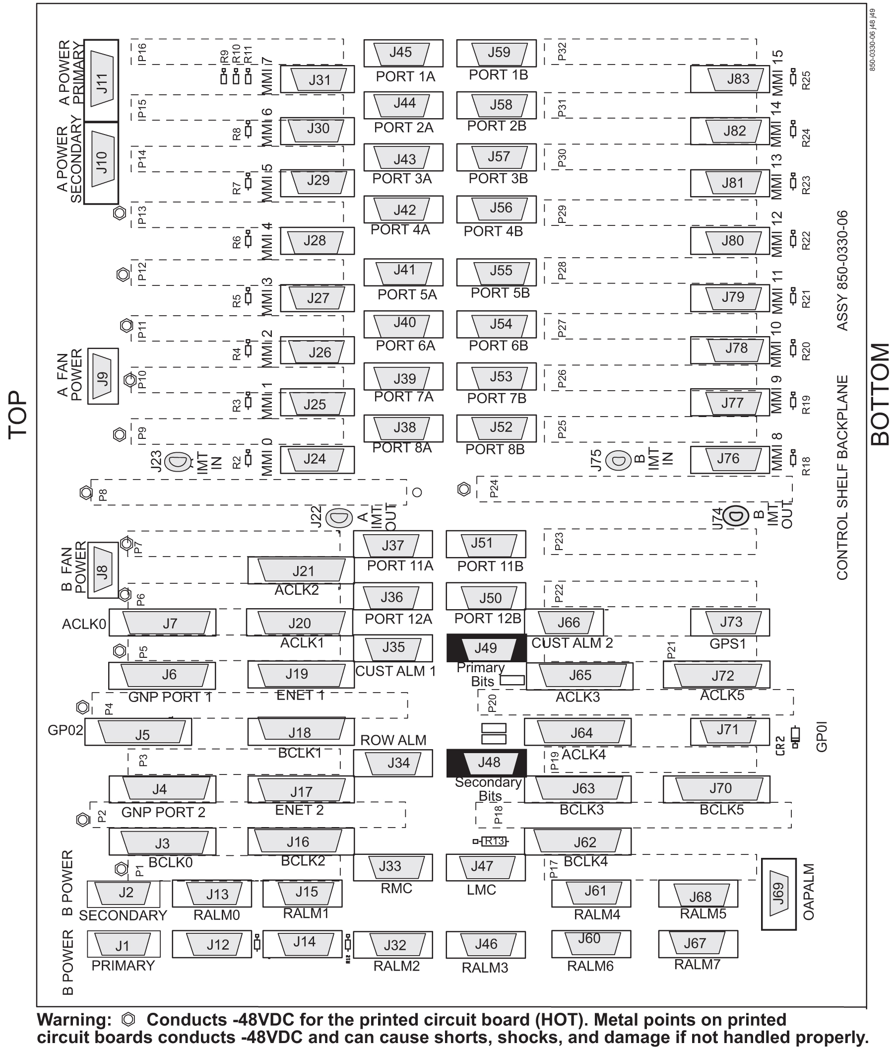
    • existing composite clock cables (P/N 830‑0226‑xx) that are routed from the primary and secondary composite clock connections of the customer clock source to the Primary BITS and Secondary BITS clock connectors J49 and J48 on the control shelf. Figure 6-31 shows the location of these connectors on the control shelf backplane.

    Figure 6-31 Control Shelf (P/N 850-0330-06 or -07) BITS Connectors


    img/t_replacing_a_and_b_frame_clock_cables_im-fig7.jpg

  2. Obtain the two new primary and secondary high‑speed source and composite clock cables (P/N 830‑0873‑xx or P/N 830‑1189‑xx). Cut out the cable ties along the route of the existing composite clock cables (P/N 830‑0226‑xx).
  3. Route the new primary and secondary high‑speed source and composite clock cables (P/N 830‑0873‑xx or P/N 830‑1189‑xx) to the frame using new cable ties.

    Note:

    Route but do not connect the new cables to the back panel at this time to avoid any accidental pull on cable connectors that could disconnect them from the composite clock source. Always route clock cables on separate cable racks, if provided, for redundancy.
  4. Prior to cable replacement, check your system for any troubles. At the EAGLE terminal, enter:
    rept-stat-trbl
    Record any troubles and ensure that no clock problems exist.

    Note:

    If clock errors exist that cannot be resolved, contact the My Oracle Support (MOS) for assistance before starting the cable replacement.
  5. Generate a clock status report to ensure that the current primary and secondary composite clock sources are running and determine which MASP is active or on standby; enter:
    rept-stat-clk

    The output displays the card status and the presence of the primary and secondary clocks, the number of cards that use clocks A and B, and the number of cards using bad clocks.

    tekelecstp 00-12-10 11:35:15 EST Rel 26.0.0
    CARD LOC = 1114 (Active )  CARD LOC  = 1116 (Standby)
    PRIMARY BITS     = Active  PRIMARY BITS      = Active
    SECONDARY BITS   = Idle    SECONDARY BITS    = Idle
    
           PSTSSTAST
           SYSTEM CLOCKIS-NRActive-----
    # Cards using CLK A = 11   # Cards with bad CLK A = 0
    # Cards using CLK B = 3    # Cards with bad CLK B = 0
    # Cards using CLK I = 0
           PSTSSTAST
    Command Completed.
    
    where:
    • CARD LOC is the TDM card location and the status of the MASP ·
    • PRIMARY BITS is the status of the primary composite clock
      • Idle indicates that the present clock source is valid but not selected as active clock source
      • Active indicates that the present clock source is valid and selected as active clock source
      • Fault indicates that no clock source is present ·
    • SECONDARY BITS is the status of the secondary composite clock
      • Idle indicates that the present clock source is valid but not selected as active clock source
      • Active indicates that the present clock source is valid and selected as active clock source
      • Fault indicates that no clock source is present ·
    • # Cards using CLK A, B, I is the number of cards using clocks A, B, and I.
    • # Cards using CLK A, B is the number of cards using clock A or clock B, when clock A or B is bad. NOTE: If any card indicates a bad clock, troubleshoot the card using the rept-stat-trbl command. Replace the card if necessary. If the bad clock error cannot be resolved, contact the unresolvable-reference.html#GUID-DA69F134-D4A7-4841-B765-BB12DD756A90 for assistance before starting the cable replacement.

    Note:

    There should be no cards using bad clocks. If any card indicates a bad clock, troubleshoot the card using the rept-stat-trbl command. Replace the card if necessary. If the bad clock error cannot be resolved, contact the My Oracle Support (MOS) for assistance before starting the cable replacement.
  6. From the output in 5, determine the IDLE clock cable.

    Caution:

    Always replace the IDLE clock cable first, whether it is the primary or secondary cable position. After the replacement of the first (IDLE) cable position, ensure the system reports the clock status properly with an ACTIVE and IDLE clock output. If the output reports the correct status the ACTIVE cable can be disconnected for replacement. Disconnecting the ACTIVE cable will transition the previously IDLE clock to the ACTIVE clock forcing the system to use the new clock cable that was installed.
  7. Perform the following to prepare the open end of the new IDLE high‑speed source and composite clock cable (P/N 830‑0873‑xx or P/N 830‑1189‑xx) for connection to the customer’s high‑speed and composite clock sources.
    1. Remove the outer insulation to expose the wires.
    2. Cut back any unused wires as shown in Figure 6-32.
    3. Slide on a 1‑1/2 inch length of shrink‑wrap tubing.
    4. Center the tubing on the end of the cable insulation before shrinking tubing with a heat gun.
    5. Ensure that each tie‑wrap strap is cut flush with the tie‑wrap head so that no sharp edges are exposed.

    Caution:

    A system with DS0A links cannot run without a composite clock source. Take extreme caution when replacing the composite clock source cables. Remove one cable at a time and confirm between removal that the other composite clock source is active.
  8. Remove the IDLE clock cable on the control shelf by removing the IDLE composite clock connector of cable (P/N 830‑0226‑xx) from the appropriate connector (J48 or J49) on the control shelf backplane.
    At the terminal, the EAGLE displays the following alarms:
        tekelecstp 00-12-10 12:17:10 EST Rel 26.0.0
    *   4306.0167  * CLOCK SYSTEM          1114-S clock failed
        tekelecstp 00-12-10 12:17:10 EST Rel 25.0.0-26.0.0
    **  4307.0169 ** CLOCK SYSTEM          1114-S, 1116-S clocks failed
        tekelecstp 00-12-10 12:05:04 EST Rel 25.0.0-26.0.0
    *   4276.0161  * CLOCK SYSTEM          1116-S clock failed
    Legend: minor (*), major (**), critical (C*), and inhibited (I) alarms. 

    Caution:

    If Both PRIMARY BITS and SECONDARY BITS clocks show FAULT condition, reconnect the cable (P/N 830‑0226‑xx) to the appropriate connector (J48 or J49) and abort this procedure. Contact the My Oracle Support (MOS) for assistance.
  9. At the output panel of the customer composite clock source, locate the end of the composite/BITS clock cable (P/N 830‑0226‑xx) that was disconnected in 8 and remove all wires.
  10. Connect the new high‑speed source clock and composite cable (P/N 830‑0873‑xx or P/N 830‑1189‑xx) to the site HS clock source.
    1. Cut the wires to length and strip.
    2. Wire‑wrap to the appropriate IDLE (primary or secondary) clock connections on the customer clock source. Refer to the cable wire coding (P/N 830‑0873‑xx or P/N 830‑1189‑xx) shown in Figure 6-32 for connection information.
      • Connect the HS clock source to the orange and white/orange wires.

      • Connect the composite clock source to the blue and white/blue wires.

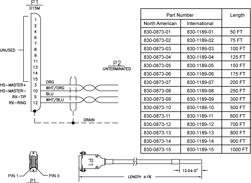
    Figure 6-32 Wire Coding of High‑Speed source and Composite Clock Cable (P/N 830‑0873‑xx or P/N 830‑1189‑xx)


    img/t_hs_clock_cable_830_0873-11891.jpg

  11. Connect P1 of the high‑speed source and composite clock cable (P/N 830‑0873‑xx or P/N 830‑1189‑xx) connector end to the appropriate IDLE ckock connector(J48 or J49). Tighten the connector with a slotted screw driver.
    After the cable (P/N 830‑0873‑xx or P/N 830‑1189‑xx) wires are attached correctly to the site clock sources and connected to the control shelf (J48 or J49), the EAGLE terminal returns the message that alarms have been cleared:
    tekelecstp 99-12-10 12:05:04 EST Rel 25.0.0-26.0.0
     4277.0113    CLOCK SYSTEM          Clock alarm(s) cleared
  12. At the EAGLE terminal, reenter the clock status command to ensure that both primary and secondary BITS clocks are available again, enter:
    rept-stat-clk
    The output indicates whether the BITS clocks are running.
    tekelecstp 00-12-10 11:35:15 EST Rel 25.0.0-26.0.0
    CARD LOC = 1114 (Active )  CARD LOC  = 1116 (Standby)
    PRIMARY BITS     = Active  PRIMARY BITS      = Active
    SECONDARY BITS   = Idle    SECONDARY BITS    = Idle
    
           PSTSSTAST
           SYSTEM CLOCKIS-NRActive-----
    # Cards using CLK A = 11   # Cards with bad CLK A = 0
    # Cards using CLK B = 3    # Cards with bad CLK B = 0
    # Cards using CLK I = 0
           PSTSSTAST
    Command Completed.
    
    Refer to 5 for output legend

    Note:

    There should be no bad clocks present in the output of the rept-stat-clk command. If bad clocks are present, contact the My Oracle Support (MOS) for assistance.
  13. Verify that you don’t have any new alarms, refer to the recorded output obtained in 4. If you check the system for clock alarms, the output should show no clock errors; enter:
    rept-stat-trbl

    Note:

    There should be no clock error messages present in the output of the rept-stat-trbl command. If clock error messages are present, contact the My Oracle Support (MOS) for assistance.
  14. Perform the following to prepare the open end of the second new high‑speed source and composite clock cable, currently the ACTIVE, (P/N 830‑0873‑xx or P/N 830‑1189‑xx) for connection to the customer’s high‑speed and composite clock sources.
    1. Remove the outer insulation to expose the wires.
    2. Cut back any unused wires as shown in Figure 6-32.
    3. Slide on a 1‑1/2 inch length of shrink‑wrap tubing.
    4. Center the tubing on the end of the cable insulation before shrinking tubing with a heat gun.
    5. Ensure that each tie‑wrap strap is cut flush with the tie‑wrap head so that no sharp edges are exposed.

    Caution:

    A system with DS0A links cannot run without a composite clock source. Take extreme caution when replacing the composite clock source cables. Remove one cable at a time and confirm between removal that the other composite clock source is active.
  15. Remove the ACTIVE clock cable on the control shelf by removing the ACTIVE composite clock connector of cable (P/N 830‑0226‑xx) from the appropriate connector (J48 or J49) on the control shelf backplane.
    At the terminal, the EAGLE displays the following alarms:
        tekelecstp 00-12-10 12:17:10 EST Rel 26.0.0
    *   4306.0167  * CLOCK SYSTEM          1114-P clock failed
        tekelecstp 00-12-10 12:17:10 EST Rel 25.0.0-26.0.0
    **  4307.0169 ** CLOCK SYSTEM          1114-P, 1116-P clocks failed
        tekelecstp 00-12-10 12:05:04 EST Rel 25.0.0-26.0.0
    *   4276.0161  * CLOCK SYSTEM          1116-P clock failed
    Legend: minor (*), major (**), critical (C*), and inhibited (I) alarms. 

    Caution:

    If Both PRIMARY BITS and SECONDARY BITS clocks show FAULT condition, reconnect the cable (P/N 830‑0226‑xx) to the appropriate connector (J48 or J49) and abort this procedure. Contact the My Oracle Support (MOS) for assistance.
  16. If you check the system for clock alarms, the output will show clock errors; enter:
    rept-stat-trbl
    The output will show any minor (*), major (**), critical (C*), and inhibited (I) alarms. The following display shows possible error messages with their alarm indicators:
    * 0014.0021 *   CARD 1116 OAM Clock A for card failed, Clock B normal
    * 0014.0022 *   CARD 1116 OAM Clock B for card failed, Clock A normal
    * 0014.0023 *   CARD 1116 OAM Clocks A and B for card failed
    **0046.0023  * CARD 1201 ATMANSI Clocks A and B for card failed
    **4307.0164 ** CLOCK SYSTEM  1114-P, 1116-P clocks failed
    Legend: minor (*), major (**), critical (C*), and inhibited (I) alarms. 
    
  17. At the output panel of the customer composite clock source, locate the end of the composite/BITS clock cable (P/N 830‑0226‑xx) that was disconnected in 15 and remove all wires.
  18. Connect the new high‑speed source clock and composite cable (P/N 830‑0873‑xx or P/N 830‑1189‑xx) to the site HS clock source.
    1. Cut the wires to length and strip.
    2. Wire‑wrap to the appropriate IDLE (primary or secondary) clock connections on the customer clock source. Refer to the cable wire coding (P/N 830‑0873‑xx or P/N 830‑1189‑xx) shown in Figure 6-32 for connection information.
      • Connect the HS clock source to the orange and white/orange wires.

      • Connect the composite clock source to the blue and white/blue wires.

    Figure 6-33 Wire Coding of High‑Speed source and Composite Clock Cable (P/N 830‑0873‑xx or P/N 830‑1189‑xx)


    img/t_hs_clock_cable_830_0873-11891.jpg

  19. Connect P1 of the high‑speed source and composite clock cable (P/N 830‑0873‑xx or P/N 830‑1189‑xx) connector end to the appropriate ckock connector(J48 or J49). Tighten the connector with a slotted screw driver.
    After the cable (P/N 830‑0873‑xx or P/N 830‑1189‑xx) wires are attached correctly to the site clock sources and connected to the control shelf (J48 or J49), the EAGLE terminal returns the message that alarms have been cleared:
    tekelecstp 99-12-10 12:05:04 EST Rel 25.0.0-26.0.0
     4277.0113    CLOCK SYSTEM          Clock alarm(s) cleared
  20. At the EAGLE terminal, reenter the clock status command to ensure that both primary and secondary BITS clocks are available again, enter:
    rept-stat-clk
    The output indicates whether the BITS clocks are running.
    tekelecstp 00-12-10 11:35:15 EST Rel 25.0.0-26.0.0
    CARD LOC = 1114 (Active )  CARD LOC  = 1116 (Standby)
    PRIMARY BITS     = Idle      PRIMARY BITS      = Idle
    SECONDARY BITS   = Active    SECONDARY BITS    = Activee
    
           PSTSSTAST
           SYSTEM CLOCKIS-NRActive-----
    # Cards using CLK A = 11   # Cards with bad CLK A = 0
    # Cards using CLK B = 3    # Cards with bad CLK B = 0
    # Cards using CLK I = 0
           PSTSSTAST
    Command Completed.
    
    Refer to 5 for output legend

    Note:

    There should be no bad clocks present in the output of the rept-stat-clk command. If bad clocks are present, contact the My Oracle Support (MOS) for assistance.
  21. Verify that you don’t have any new alarms, refer to the recorded output obtained in 4. If you check the system for clock alarms, the output should show no clock errors; enter:
    rept-stat-trbl

    Note:

    There should be no clock error messages present in the output of the rept-stat-trbl command. If clock error messages are present, contact the My Oracle Support (MOS) for assistance.
You have completed the cable replacement procedure for the high‑speed source and composite clock cables on EAGLE systems with backplane (P/N 850‑0330‑06/07).

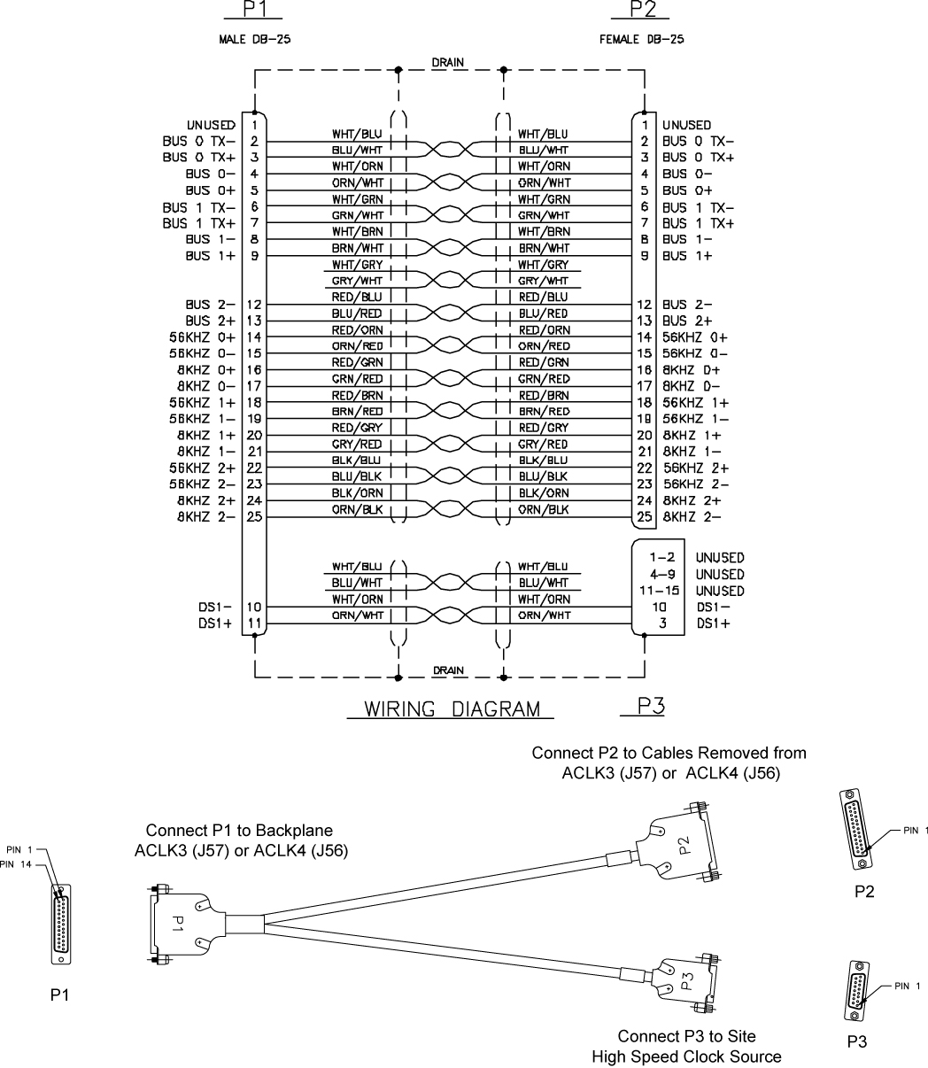
6.5.2 HS Source and Composite Clock Cables on Backplane P/N 850‑0330‑03/04

On systems with control shelf backplane (P/N 850‑0330‑03/04), the high‑speed source clock cable (P/N 830‑0873‑xx or P/N 830‑1189‑xx) sends only high‑speed clock signals to the EAGLE. The existing composite clock cables (P/N 830‑0226‑xx) continue to provide the low‑speed clock connections to connectors J42 and J41 (Primary BITS and Secondary BITS) on the backplane. The HS cables (P/N 830‑0873‑xx or P/N 830‑1189‑xx) send the HS primary and secondary clock signals through adapter cables (P/N 830‑0846‑01) to connectors J57 and J56 on the backplane. The two connectors are labeled ACLK3 and ACLK4.

This procedure describes the steps required to install the HS clock cables on the EAGLE with control shelf backplane (P/N 850‑0330‑03/04) using adapter cable (P/N 830‑0846‑01).

Caution:

A system with DS0A links cannot run without a composite clock source. This procedure requires removing and replacing the ACLK3 cables to frame 3 (shelves 4100, 4200, 4300) and frame 4, ACLK4 (shelves 5100, 5200, 5300). Take extreme caution when removing and replacing the ACLK cables. Remove one cable at a time and confirm before removal that the BCLK clock source is active to that frame.

Caution:

Perform this procedure during a maintenance window.

Caution:

Prior to adding or replacing the high‑speed source and composite clock cables, perform an EAGLE system health check.

Caution:

HS clock alarms are only generated for ATM LIM cards and E1/T1 MIM if the card is provisioned to use the HS clock.

Caution:

Always replace the IDLE clock cable first, whether it's the primary or secondary cable position. After the replacement of the first (Idle) cable position, ensure the system reports the clock status properly with an active and idle clock output. If the output reports the correct status you are know able to replace the active cable which will force the system to use the new clock cable (idle) position and it will transition state to active.

Caution:

Connectors ACLK3 and ACLK4 propagate system A clocks to frame 3 (shelves 4100, 4200, and 4300) and frame 4 (shelves 5100, 5200, 5300). System A clock signals to cards in these shelves will be lost during this procedure. If the EAGLE contains these shelves with cards installed the cards switch automatically to the system B clock sources when the A clock sources are removed.

Note:

In this procedure, the high‑speed clock status indicated in the output of the rept-stat-clk command reflects the presence of at least one ATM LIM card or E1/T1 MIM in the system. The status fields remain empty until the card is configured to use the high‑speed clock.

Procedure — Replace or Add HS source Timing Clock Cables with:backplane (P/N 850‑0330‑03/04)

  1. Prior to cable replacement, check your system for any troubles. At the EAGLE terminal, enter:
    rept-stat-trbl
    Record any troubles and ensure that no clock problems exist.

    Note:

    If clock errors exist that cannot be resolved, contact the My Oracle Support (MOS) for assistance before starting the cable replacement.
  2. Generate a clock status report to ensure that the current primary and secondary composite clock sources are running and determine which MASP is active or on standby; enter:
    rept-stat-clk

    The output displays the card status and the presence of the primary and secondary clocks, the number of cards that use clocks A and B, and the number of cards using bad clocks.

    tekelecstp 00-12-10 11:35:15 EST Rel 26.0.0
    CARD LOC = 1114 (Active )  CARD LOC  = 1116 (Standby)
    PRIMARY BITS     = Active  PRIMARY BITS      = Active
    SECONDARY BITS   = Idle    SECONDARY BITS    = Idle
    
           PSTSSTAST
           SYSTEM CLOCKIS-NRActive-----
    # Cards using CLK A = 11   # Cards with bad CLK A = 0
    # Cards using CLK B = 3    # Cards with bad CLK B = 0
    # Cards using CLK I = 0
           PSTSSTAST
    Command Completed.
    
    where:
    • CARD LOC is the TDM card location and the status of the MASP ·
    • PRIMARY BITS is the status of the primary composite clock
      • Idle indicates that the present clock source is valid but not selected as active clock source
      • Active indicates that the present clock source is valid and selected as active clock source
      • Fault indicates that no clock source is present ·
    • SECONDARY BITS is the status of the secondary composite clock
      • Idle indicates that the present clock source is valid but not selected as active clock source
      • Active indicates that the present clock source is valid and selected as active clock source
      • Fault indicates that no clock source is present ·
    • # Cards using CLK A, B, I is the number of cards using clocks A, B, and I.
    • # Cards using CLK A, B is the number of cards using clock A or clock B, when clock A or B is bad. NOTE: If any card indicates a bad clock, troubleshoot the card using the rept-stat-trbl command. Replace the card if necessary. If the bad clock error cannot be resolved, contact the My Oracle Support (MOS) for assistance before starting the cable replacement.

    Note:

    There should be no cards using bad clocks. If any card indicates a bad clock, troubleshoot the card using the rept-stat-trbl command. Replace the card if necessary. If the bad clock error cannot be resolved, contact the My Oracle Support (MOS) for assistance before starting the cable replacement.
  3. Before starting the cable replacement, physically locate the:
    • two new HS clock cables (P/N 830‑0873‑xx) to be connected to the customers HS clock source.

    • adapter cables (P/N (830‑0846‑01).

    • the existing composite clock cables (P/N 830‑0226‑xx) connected to the primary and secondary BITS clock sources and connectors (J42 and J41) on the control shelf backplane.

    • any existing ACLK cables connected to ACLK3 and ACLK4 (J57 and J56) on the control shelf backplane.

      Note:

      Depending on the amount of extension shelves in the system the cables connecting ACLK3 and ACLK4 to extension frames may not be installed. If these cables are not installed the P2 (DB25) end of the adapter cables (P/N 830‑0846‑01) are not used. Secure the unused P2 end of the adapter cables with tie‑wraps.

    Figure 6-34 shows the location of these connectors on the control shelf backplane.

    Figure 6-34 Control Shelf (P/N 850-0330-03 or -04) BITS Connectors
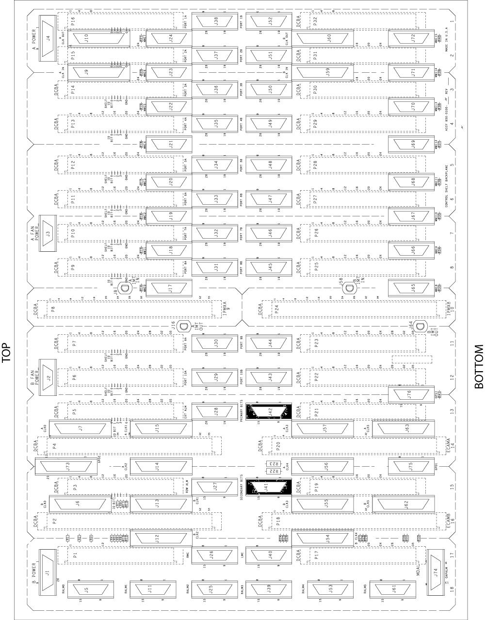

    img/850-0330-04.jpg

    warning:

    Metal points on the PCB conduct ‑48VDC and can cause shorts, shocks, and damage if not handled properly.
  4. Obtain the two new primary and secondary high‑speed source clock cables (P/N 830‑0873‑xx or P/N 830‑1189‑xx). Cut out the cable ties along the route of the existing composite clock cables (P/N 830‑0226‑xx).
  5. Route the new HS source clock cables (P/N 830‑0873‑xx) using new cable ties. Route the primary and secondary HS clock cables from the customer’s high‑speed clock sources to the EAGLE control shelf backplane near connectors J57 and J56.

    Note:

    Route but do not connect the new cables to the backpanel at this time to avoid any accidental pull on cable connectors that could disconnect them from the composite clock source. Always route clock cables on separate cable racks, if provided, for redundancy.

    Ensure that each tie‑wrap strap is cut flush with the tie‑wrap head so that no sharp edges are exposed.

  6. Prepare the open end of the new primary high‑speed source and composite clock cable (P/N 830‑0873‑xx or P/N 830‑1189‑xx) for connection to the customer’s primary clock and high‑speed clock sources. Remove the outer insulation to expose the wires.
  7. Slide on a 1‑1/2 inch length of shrink‑wrap tubing. Center the tubing on the end of the cable insulation before shrinking tubing with a heat gun.
  8. Connect the open cable end wires to the site primary and secondary high‑speed clock sources. Connect the primary and secondary HS source clock source cables (P/N 830‑0873‑xx or P/N 830‑1189‑xx) to the wires attached to connector P1, pins 10 and 3, on each cable.

    Figure 6-354 shows the connector pin outs of the high‑speed source clock cable adapter cable (P/N 830‑0873‑xx or P/N 830‑1189‑xx).

    Figure 6-35 Wire Coding of High‑Speed source and Composite Clock Cable (P/N 830‑0873‑xx or P/N 830‑1189‑xx)


    img/t_hs_clock_cable_830_0873-11891.jpg

    Caution:

    A system with DS0A links cannot run without a composite clock source. Take extreme caution when replacing the composite clock source cables. Remove one cable at a time and confirm between removal that the other composite clock source is active.

    Note:

    If the ACLK3 or ACLK4 connectors did not have cables connected as indicated in 3 the P2 (DB 25) end of the adapter cable is not used. Using tie‑wraps secure the P2 end of the cable.
  9. Start adding the primary HS clock cable (P/N 830‑0873‑xx) and adapter cable (P/N 830‑0846‑01) on the control shelf by removing the cable end at ACLK3 connector J57.

    At the terminal, the EAGLE displays alarms indicating loss of ACLK to cards on shelves 4100, 4200, and 4300 with BCLK normal.

  10. Generate a clock status report to confirm that the secondary composite clock is now active. Enter the following command:
    rept-stat-clk
    The system returns output similar to the following:
    tekelecstp 00-12-10 11:35:15 EST Rel 26.0.0
    CARD LOC = 1114 (Active   ) CARD LOC = 1116 (Standby  )
    PRIMARY BITS     = Fault    PRIMARY BITS     = Fault
    SECONDARY BITS   = Active   SECONDARY BITS   = Active
           PSTSSTAST
           SYSTEM CLOCKIS-NRActive-----
    # Cards using CLK A = 11   # Cards with bad CLK A = 0
    # Cards using CLK B = 3    # Cards with bad CLK B = 0
    # Cards using CLK I = 0
           PSTSSTAST
    Command Completed.
    

    Refer to 2 for output legend.

    Caution:

    If cards on shelves 4100, 4200, and 4300 indicate bad ACLK and BCLK reconnect the ACLK3 cable to connector J57 and abort this procedure. Contact the My Oracle Support (MOS) for assistance.

    Note:

    In the following steps reference Figure 6-36 for cabling connections.
  11. Connect the adapter cable (P/N 830‑0846‑01) P1 (DB25) to ACLK3 connector J57 on the control shelf backplane. Tighten the connector with a slotted screw driver.

    Figure 6-36 High-Speed source Timing Adapter Cable (P/N 830‑0846‑01)


    img/t_high_speed_adapter_cbl_830-0846-01.jpg

  12. Connect the adapter cable (P/N 830‑0846‑01) P2 (DB25) to the end of the ACLK cable removed in Step\ Tighten the connector with a slotted screw driver.

    This step reconnects the ACLK3 signals to shelves 4100, 4200, 4300.

    At the terminal, the EAGLE displays messages indicating return of ACLK to cards on shelves 4100, 4200, and 4300 with BCLK normal.

  13. Connect the primary HS source clock cable (P/N 830‑0873‑xx) connector end to adapter cable (P/N 830‑0846‑01) P3 (DB15). Tighten the connector with a slotted screw driver.

    This step connects the customer primary HS clock source to the TDM card through the unused contacts of the ACLK3 connector J57.

    After the wires are attached correctly, the EAGLE terminal returns the following message:
    tekelecstp 00-12-10 12:05:04 EST Rel 26.0.0
     4277.0113    CLOCK SYSTEM          Clock alarm(s) cleared
    
  14. At the EAGLE terminal, reenter the clock status command to ensure that both primary and secondary BITS clocks are available again, enter:
    rept-stat-clk
    The output indicates whether the BITS clocks are running. In this example, the secondary BITS clock is still active and the primary BITS clock is running but in standby mode.
    tekelecstp 00-12-10 11:35:15 EST Rel 25.0.0-26.0.0
    CARD LOC = 1114 (Active  ) CARD LOC = 1116 (Standby)
    PRIMARY BITS     = Idle    PRIMARY BITS     = Idle
    SECONDARY BITS   = Active  SECONDARY BITS   = Active
    
           PSTSSTAST
           SYSTEM CLOCKIS-NRActive-----
    # Cards using CLK A = 11   # Cards with bad CLK A = 0
    # Cards using CLK B = 3    # Cards with bad CLK B = 0
    # Cards using CLK I = 0
           PSTSSTAST
    Command Completed.
    
    Refer to 2 for output legend

    Note:

    There should be no bad clocks present in the output of the rept-stat-clk command. If bad clocks are present, contact the My Oracle Support (MOS) for assistance.
  15. Verify that you don’t have any new alarms, refer to the recorded output obtained in 1. If you check the system for clock alarms, the output should show no clock errors; enter:
    rept-stat-trbl

    Note:

    There should be no clock error messages present in the output of the rept-stat-trbl command. If clock error messages are present, contact the My Oracle Support (MOS) for assistance.
  16. To continue this procedure to add the secondary HS clock cables go to 13.

    Caution:

    A system with DS0A links cannot run without a composite clock source. Take extreme caution when replacing the ACLK to extension shelf cables. Remove one cable at a time and confirm between removal that the other composite clock source on that shelf is active.
  17. Start adding the secondary HS clock cable the cable (P/N 830‑0873‑xx) and adapter (P/N 830‑0846‑01) on the control shelf by removing the cable end at ACLK4 connector J56.

    At the terminal, the EAGLE displays alarms indicating loss of ACLK to cards on shelves 5100, 5200, and 5300 and BCLK normal.

  18. Generate a clock status report to confirm that cards on shelves 5100, 5200, and 5300 are using the BCLK. Enter the following command:
    rept-stat-clk
    The output indicates whether the BITS clock is running again. In this example, the primary BITS clock is active and the secondary BITS clock has failed.
    tekelecstp 00-12-10 11:35:15 EST Rel 26.0.0
    CARD LOC = 1114 (Active   )CARD LOC = 1116 (Standby  )
    PRIMARY BITS     = Active  PRIMARY BITS     = Active
    SECONDARY BITS   = Fault   SECONDARY BITS   = Fault
           PSTSSTAST
           SYSTEM CLOCKIS-NRActive-----
    # Cards using CLK A = 11   # Cards with bad CLK A = 0
    # Cards using CLK B = 3    # Cards with bad CLK B = 0
    # Cards using CLK I = 0
           PSTSSTAST
    Command Completed.
    

    Refer to Step 2 for output legend.

    Caution:

    If cards on shelves 5100, 5200, and 5300 indicate bad ACLK and BCLK, reconnect the ACLK3 cable to connector J57 and abort this procedure. Contact the My Oracle Support (MOS) for assistance.
  19. Connect the adapter cable (P/N 830‑0846‑01) P1 (DB25) to ACLK4 connector J56 on the control shelf backplane. Tighten connector with slotted screw driver.

    Note:

    If the ACLK3 and ACLK4 connectors did not have cables connected as indicated in 3 the P2 (DB 25) end of the adapter cable is not used. Using tie‑wraps secure the P2 end of the cable.
  20. Connect the adapter cable (P/N 830‑0846‑01) P2 (DB25) to the end of the ACLK cable removed in 3. Tighten the connector with a slotted screw driver. This step reconnects the ACLK4 signals to shelves 5100, 5200, 5300.

    At the terminal, the EAGLE displays messages indicating return of ACLK to cards on shelves 5100, 5200, and 5300 and BCLK normal.

  21. Connect the secondary HS source clock cable (P/N 830‑0873‑xx) connector end to adapter cable (P/N 830‑0846‑01) P3 (DB15). Tighten the connector with a slotted screw driver.

    This step connects the customer secondary HS clock source to the TDM card through the unused contacts of the ACLK4 connector J56.

    After the cables are attached correctly, the EAGLE terminal returns the following message:
    tekelecstp 00-12-10 12:05:04 EST Rel 26.0.0
      4277.0113    CLOCK SYSTEM          Clock alarm(s) cleared
    
  22. At the EAGLE terminal, reenter the clock status command to ensure that both primary and secondary BITS clocks are available again, enter:
    rept-stat-clk
    The output indicates whether the BITS clocks are running. In this example, the secondary BITS clock is still active and the primary BITS clock is running but in standby mode.
    tekelecstp 00-12-10 11:35:15 EST Rel 26.0.0
    CARD LOC = 1114 (Active   )CARD LOC = 1116 (Standby  )
    PRIMARY BITS     = Active  PRIMARY BITS     = Active
    SECONDARY BITS   = Fault   SECONDARY BITS   = Fault
           PSTSSTAST
           SYSTEM CLOCKIS-NRActive-----
    # Cards using CLK A = 11   # Cards with bad CLK A = 0
    # Cards using CLK B = 3    # Cards with bad CLK B = 0
    # Cards using CLK I = 0
           PSTSSTAST
    Command Completed.
    

    Refer to 2 for output legend.

    Note:

    There should be no bad clocks present in the output of the rept-stat-clk command. If bad clocks are present, contact the My Oracle Support (MOS) for assistance.
  23. Verify that you don’t have any new alarms, refer to the recorded output obtained in 1. If you check the system for clock alarms, the output should show no clock errors; enter:
    rept-stat-trbl

    Note:

    There should be no clock error messages present in the output of the rept-stat-trbl command. If clock error messages are present, contact the My Oracle Support (MOS) for assistance.
You have completed the cable replacement procedure for the high‑speed source clock cables on EAGLE systems with control shelf backplane (P/N 850‑0330‑03/04.

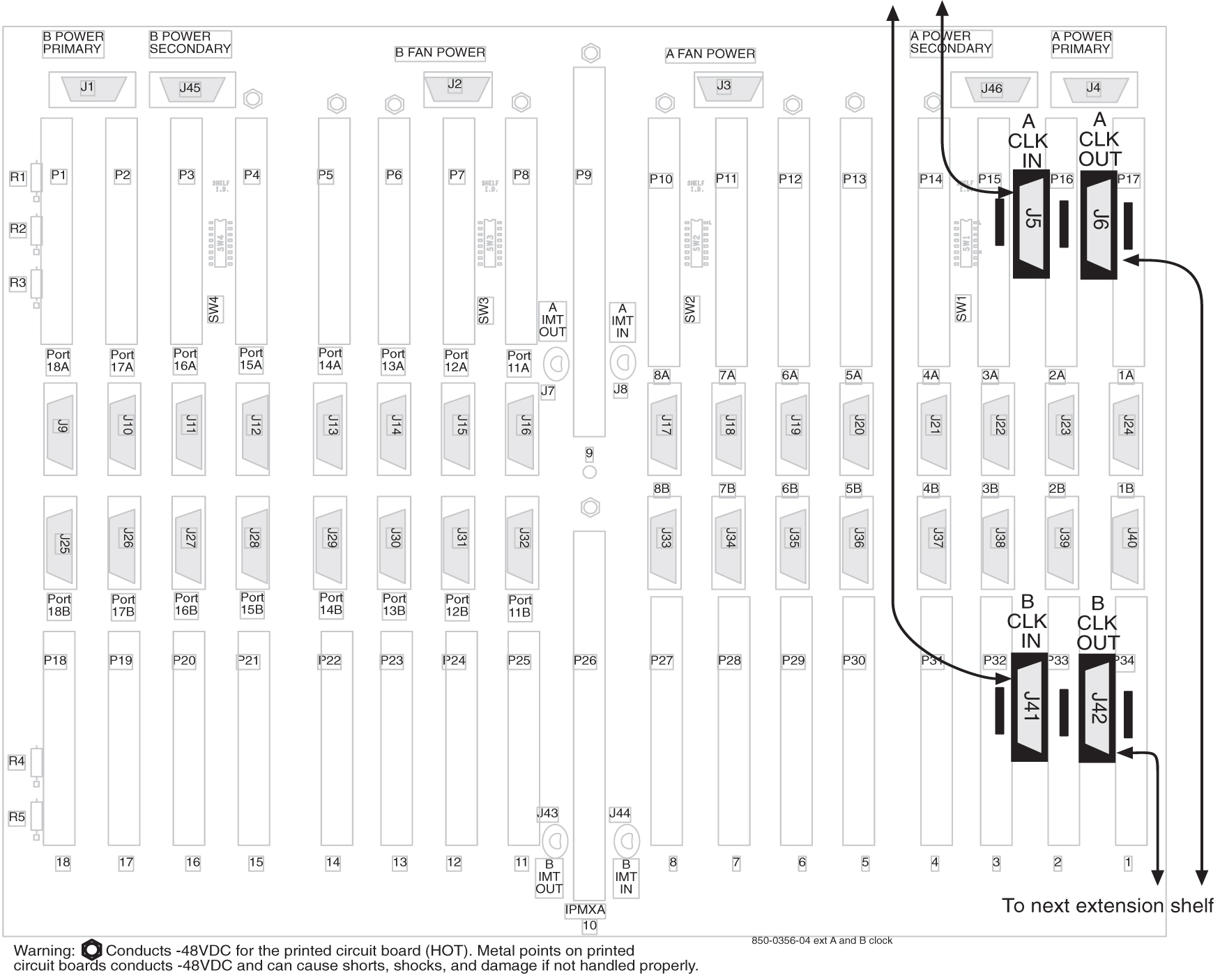
6.6 A Clock and B Clock Cable Replacement

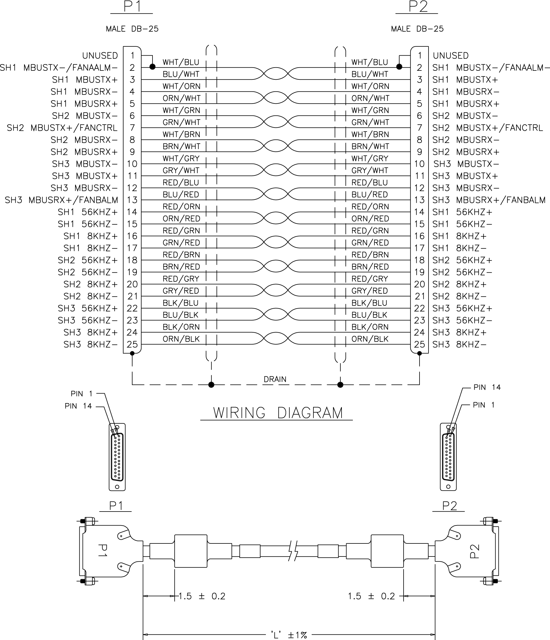
Proper support for HMUX and alarm reporting require that all A and B clock cables be of P/N 830-0398-xx (domestic) or P/N 830-1150-xx (international). Clock cables of P/N 830-0404-xx must be replaced. The A and B clock cables typically are from the control shelf and those coming in from an extension shelf. These cables contain proper alarm alert capabilities and support HMUX. See Figure 6-37 and Figure 6-38.

This procedure can also be used for regular clock cable replacement.

Perform the replacement during a maintenance window and prior to fan assembly installation.

Figure 6-37 Cable (P/N 830-0404-xx)


img/t_replacing_a_and_b_frame_clock_cables_im-fig1.jpg

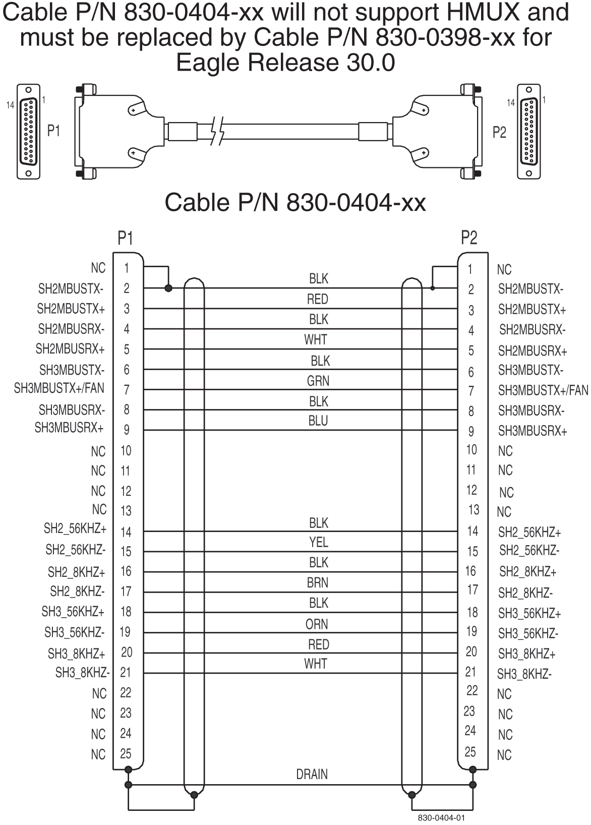
Figure 6-38 Cable 830-0398-xx or 830-1150-xx


img/t_a_b_clock_cable_830_0398_1150.jpg

6.6.1 Procedure — Replacing A Frame Clock Cables

This procedure explains the replacement of one A frame clock cable. The steps show the replacement of one frame clock cable and are repeated for every frame clock cable that is to be replaced.

  1. Remove the plastic panels from the back of all shelves that require the frame clock cables be replaced.
  2. Install Pin Protector Assembly on all shelves that require the frame clock cables be replaced.

    The pin protectors are placed over the ID pins directly to the right and left of the A CLK IN cables connectors on each shelf. Shelf ID pins must be covered with pin protectors. If contact is made with the ID pins, the shelf may lose its identity.

  3. Connect a laptop or access by way of a monitor, the EAGLE system and start a terminal emulator program such as ProComm.
  4. Open a captured file by simultaneously pressing the Alt and F1 keys

    Name the file the last four digits of the [NT#]xxyyzz.CAP

    Example: 2641E1T1_A.cap

  5. Issue the command to report clock status.
    rept-stat-clk
    Response to the clock status command is displayed.
    
    tekelecstp 03-02-10 05:34:03 HST Rel XX.x.x-XX.x.x
       rept-stat-clk
       Command entered at termoinal #1.
    ;
       tekelecstp 03-02-10 05:34:03 HST Rel XX.x.x-XX.x.x
       CARD LOC= 1114 (Standby)    CARD LOC= 1116 (Active)
       PRIMARY BITS     = Active PRIMARY BITS       = Active
       SECONDARY BITS   = Idle    SECONDARY BITS     = Idle
       HS PRIMARY CLK   = Active HS PRIMARY CLK     = Active
       HS SECONDARY CLK = Idle


        HS SECONDARY CLK   = Idle
                              PST           SST       AST
       SYSTEM CLOCK           IS-NR         Active    -----
       # Cards using CLK A = 7    # Cards with bad CLK A = 000
       # Cards using CLK B = 0    # Cards with bad CLK B = 000
       # Cards using CLK I = 0
       Command Completed.
                              PST           SST       AST
       HS SYSTEM CLOCK        IS-NR         Active    -----
       # Cards using HS CLK A = 1   # Cards with bad HS CLK A = 0
       # Cards using HS CLK B = 0   # Cards with bad HS CLK B = 0
       # Cards using HS CLK I = 0
       
       Command Completed.
    ;
    
  6. Verify that both BITS clocks are either in IDLE or ACTIVE state on both ACTIVE and STANDBYMASP

    All underlined cards-with-bad-CLK values should equal zero.

  7. For the A frame clock cable being replaced remove all tie wraps or lacing cord securing the cable in the frame.
  8. Remove the A frame clock cable from the shelf’s A CLKOUT connector.

    Figure 6-39 Backplane P/N 850-0330-06 or -07 Control Shelf


    img/t_replacing_a_and_b_frame_clock_cables_im-fig3.jpg

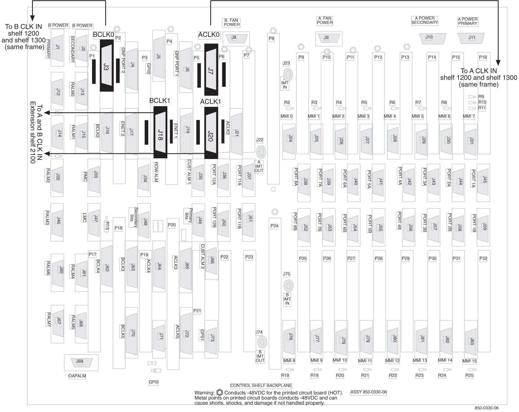
    Figure 6-40 Backplane P/N 850-0356-04 Extension Shelf


    img/t_replacing_a_and_b_frame_clock_cables_im-fig4.jpg

  9. Remove the other end of the frame clock cable from the next shelf’s A CLKIN connector.
  10. Select the new frame clock cable (P/N 830-0398-xx or P/N 830-1150-xx) and connect it to the A CLKOUT connector, refer to 8
  11. Route the clock cable in the frame following the routing directions in this manual.
  12. Connect the other end of the new frame clock cable (P/N 830-0398-xx or P/N 830-1150-xx) from A CLKOUT, refer to 10, to the next shelf’s A CLKIN connector.
  13. Issue the command to report clock status.
    rept-stat-clk
    Response to the clock status command is displayed.
    
    tekelecstp 03-02-10 05:34:03 HST Rel XX.x.x-XX.x.x
       rept-stat-clk
       Command entered at termoinal #1.
       
    ;
       tekelecstp 03-02-10 05:34:03 HST Rel XX.x.x-XX.x.x
       CARD LOC= 1114 (Standby)    CARD LOC= 1116 (Active)
       PRIMARY BITS     = Active PRIMARY BITS       = Active
       SECONDARY BITS   = Idle    SECONDARY BITS     = Idle
       HS PRIMARY CLK   = Active HS PRIMARY CLK     = Active
       HS SECONDARY CLK = Idle


        HS SECONDARY CLK   = Idle
                              PST           SST       AST
       SYSTEM CLOCK           IS-NR         Active    -----
       # Cards using CLK A = 7    # Cards with bad CLK A = 
    000
       # Cards using CLK B = 0    # Cards with bad CLK B = 
    000
       # Cards using CLK I = 0
       Command Completed.
                              PST           SST       AST
       HS SYSTEM CLOCK        IS-NR         Active    -----
       # Cards using HS CLK A = 1   # Cards with bad HS CLK A = 0
       # Cards using HS CLK B = 0   # Cards with bad HS CLK B = 0
       # Cards using HS CLK I = 0
       
       Command Completed.
    ;
    
  14. Verify that both BITS clocks are either in IDLE or ACTIVE state on both ACTIVE and STANDBYMASP

    All underlined cards-with-bad-CLK values should equal zero.

  15. If any other A frame clock cables need to be replaced in the system repeat 5 through 14
  16. After all the A frame clock cables in the system are replaced secure the cables with tie wraps or lacing cord according to specifications.
  17. If any B frame clock cables need to be replaced move to the next Procedure Replacing B Frame Clock Cables in this document
  18. If no other frame clock cables are to be replaced and if the pin protectors are needed remove the ID pin protectors.
  19. If no other frame clock cables need replacing, return the plastic panels that were removed for this procedure to original locations. Put all plastic panels back in place.

6.6.2 Procedure — Replacing B Frame Clock Cables

This procedure explains the replacement of one B frame clock cable. The steps show the replacement of one frame clock cable and are repeated for every frame clock cable that is to be replaced.

  1. Remove any plastic panels from the back of all shelves that require the frame clock cables replaced.
  2. Install pin protectors on all shelves that require the frame clock cables to be replaced.

    The pin protectors are placed over the ID pins directly to the right and left of the B CLK IN cables connectors on each shelf. Shelf ID pins must be covered with pin protectors. If contact is made with the ID pins, the shelf may lose its identity.

  3. Connect a laptop or access by way of a monitor, the EAGLE system and start ProComm or a terminal emulator program.
  4. Open a captured file by simultaneously pressing the Alt and F1 keys.

    Name the file the last four digits of the [NT#]xxyyzz.CAP

    Example: 2641E1T1_A.cap

  5. Issue the command to report clock status.
    rept-stat-clk
    Response to the clock status command is displayed.
    
    tekelecstp 03-02-10 05:34:03 HST Rel XX.x.x-XX.x.x
       rept-stat-clk
       Command entered at termoinal #1.
    ;
       tekelecstp 03-02-10 05:34:03 HST Rel XX.x.x-XX.x.x
       CARD LOC= 1114 (Standby)    CARD LOC= 1116 (Active)
       PRIMARY BITS     = Active PRIMARY BITS       = Active
       SECONDARY BITS   = Idle    SECONDARY BITS     = Idle
       HS PRIMARY CLK   = Active HS PRIMARY CLK     = Active
       HS SECONDARY CLK = Idle


        HS SECONDARY CLK   = Idle
                              PST           SST       AST
       SYSTEM CLOCK           IS-NR         Active    -----
       # Cards using CLK A = 7    # Cards with bad CLK A = 
    000
       # Cards using CLK B = 0    # Cards with bad CLK B = 
    000
       # Cards using CLK I = 0
       Command Completed.
                              PST           SST       AST
       HS SYSTEM CLOCK        IS-NR         Active    -----
       # Cards using HS CLK A = 1   # Cards with bad HS CLK A = 0
       # Cards using HS CLK B = 0   # Cards with bad HS CLK B = 0
       # Cards using HS CLK I = 0
       
       Command Completed.
    ;
    
  6. Verify that both BITS clocks are either in IDLE or ACTIVE state on both ACTIVE and STANDBYMASP

    All underlined cards-with-bad-CLK values should equal zero.

  7. For the B frame clock cable being replaced remove all tie wraps or lacing cord securing the cable in the frame.
  8. Remove the B frame cable from the shelf’s B CLKOUT connector.

    Figure 6-41 Backplane P/N 850-0330-06 or -07 Control Shelf


    img/t_replacing_a_and_b_frame_clock_cables_im-fig3.jpg

    Figure 6-42 Backplane P/N 850-0356-04 Extension Shelf


    img/t_replacing_a_and_b_frame_clock_cables_im-fig4.jpg

  9. Remove the other end of the frame clock cable from the next shelf’s B CLKIN connector.
  10. Select a new frame clock cable and connect it to the B CLKOUT connector, refer to 8.
  11. Route the clock cable in the frame following the routing directions in this manual.
  12. Connect the other end of the new frame clock cable from B CLKOUT, refer to 10, to the next shelf’s B CLKIN connector.
  13. Issue the command to report clock status.
    rept-stat-clk
    Response to the clock status command is displayed.
    
    tekelecstp 03-02-10 05:34:03 HST Rel XX.x.x-XX.x.x
       rept-stat-clk
       Command entered at termoinal #1.
       
    ;
       tekelecstp 03-02-10 05:34:03 HST Rel XX.x.x-XX.x.x
       CARD LOC= 1114 (Standby)    CARD LOC= 1116 (Active)
       PRIMARY BITS     = Active PRIMARY BITS       = Active
       SECONDARY BITS   = Idle    SECONDARY BITS     = Idle
       HS PRIMARY CLK   = Active HS PRIMARY CLK     = Active
       HS SECONDARY CLK = Idle


        HS SECONDARY CLK   = Idle
                              PST           SST       AST
       SYSTEM CLOCK           IS-NR         Active    -----
       # Cards using CLK A = 7    # Cards with bad CLK A = 
    000
       # Cards using CLK B = 0    # Cards with bad CLK B = 
    000
       # Cards using CLK I = 0
       Command Completed.
                              PST           SST       AST
       HS SYSTEM CLOCK        IS-NR         Active    -----
       # Cards using HS CLK A = 1   # Cards with bad HS CLK A = 0
       # Cards using HS CLK B = 0   # Cards with bad HS CLK B = 0
       # Cards using HS CLK I = 0
       
       Command Completed.
    ;
    
  14. Verify that both BITS clocks are either in IDLE or ACTIVE state on both ACTIVE and STANDBYMASP

    All underlined cards-with-bad-CLK values should equal zero.

  15. If any other B frame clock cables need to be replaced in the system, repeat 5 through 14.
  16. After all the B frame clock cables in the system are replaced, secure the cables with tie wraps or lacing cord according to specifications.
  17. If no other frame clock cables are to be replaced and if the pin protectors are needed, remove the ID pin protectors.
  18. If no other frame clock cables need replacing, return the plastic panels that were removed for these procedures to original locations. Put all plastic panels back in place.

6.7 Termination of Alarm, Clock Supply, and Terminal Cables

Termination information for the alarm, Building Integrated Timing System (BITS), and terminal cables is furnished in the “Cable Running List” in the Equipment Specification for the site.

All of the alarm and clock supply cables are shielded and contain wires with solid conductors. They are intended for wire-wrap terminations at the customer end. The terminal cables have connectors on both ends.

danger:

Always wear a wrist strap or other electrostatic protection when handling printed circuit cards and other electrostatic-sensitive devices.

Recommended Tools

Oracle tools should be labeled “Property of ORACLE” with either a press-on Field Tool Identification label or Field Tool Identification wrap.

  • Safety glasses

  • Tie-wrap tool

  • Diagonal cutters

  • Flush cutters

  • Wire-wrap gun and bit

  • Slotted screwdriver with 1/8-inch blade and 8-inch shank

  • Stripper

  • Heat gun

6.7.1 Alarm Cable Termination

The rack alarm cable for the control frame may be factory installed at both ends or the row alarm cable may come from the factory installed at the alarm end-panel only.

danger:

Always wear a wrist strap or other electrostatic protection when handling printed circuit cards and other electrostatic-sensitive devices.

warning:

Always trim tie-wraps flush and turn the trimmed tie-wraps to the rear of the cable bundle, when facing the back of the frame.
The rack alarm cables lead from ports in the system control backplane and connect with other frames in the row.

The backplane alarm ports are:

  • FAP (Frame and Alarm Panel) in the control frame J13 on 850-0330-06 or -07

  • FAP extension frame 00 J15 on P/N 850-0330-06 or -07

  • FAP extension frame 01 J32 on P/N 850-0330-06 or -07

  • FAP extension frame 02 J46 on P/N 850-0330-06 or -07

  • FAP extension frame 03 J61 on P/N 850-0330-06 or -07

  • FAP extension frame 04 J68 on P/N 850-0330-06 or -07

  • End panel J34 on P/N 850-0330-06 or -07 (use cable row alarm cable 830-1145-01)

  • J35 and J66 o 850-0330-06 or -07 to holdover clock

  • J69 on 850-0330-06 or -07 to OAPF

  • LMC J47 on850-0330-06 or -07

  • RMC J33 on 850-0330-06 or -07

From the rear of the frame these cables should be routed from the connector around the left side of the frame. Route the cables up the side of the frame to the FAP and secure the cables with lacing cord to the cross arms on the side of the frame. Across the top of the frame secure the cables to the cross arms above the FAP with lacing cord also.

Note:

Alarm cables should not be formed with power cables and should have a lacing cord approximately every three inches. There should be no less than two lacing cord ties between frames.

Note:

If the end panel does not mount on the control frame, the cable will route the same as alarm rack cables, from port J34 on backplane 850-0330-06 or -07 from the rear of the frame, up the left side of the frame, across the top of the FAP, and formed and dressed with the alarm rack cables to the end panel.

The following cables have connectors for termination on the control shelf. The cables listed below are cross-referenced for additional connector information:

Cables are supplied as follows:

  • With the exception of the rack alarms and the row alarm, one of each type of alarm cable is supplied for each system.

  • One rack alarm cable is supplied for each Control, Extension, or OAP Frame present in the system.

  • One row alarm cable for each system equipped with an alarm end panel containing alarm indicator lamps.

6.7.2 Terminate Clock Supply Cables

The Building Integrated Timing System (BITS) clocks come directly from the central office BITS clock source or indirectly from an optional holdover clock installed in the system.

See Holdover Clock Installation for optional holdover clock installation information.

Refer to BITS Clock Connectors for cable connector information.

6.7.3 Terminal Cables

There are 16 I/O ports on the control shelf backplane that are used to support external printers, terminals, or modems.

Use terminal/printer cable 830-0535-xx or 830-1154-xx. Different combinations of adapters are possible, see Table 6-3.

Refer to Cables and Adapters for detailed cable and adapter connector information.

  1. See the “Cable Running List” in the Equipment Specification to determine how to connect the external cables.
    All cable ends must be labeled with “TO” and “FROM” location information from Port to Backplane.
  2. Place the cables on the cable rack.
    Feed the cable ends (with connectors) down the side of the system, outside the cable tie bars, around the top or bottom edge of the control shelf and fan out to the connectors.
  3. Secure each connector to the designated receptacle on the control shelf backplane.
    Plug the connector in, start one of the connector screws, fully tighten the second screw, then fully tighten the first screw.
  4. Tie-wrap each cable to the cable tie bar at the rear of the shelf.
  5. Dress the cables neatly and tie-wrap to the cable tie bars at the side of the frame.
    Pull the slack in the cable back toward the other end of the cables and lace to the cable rack.
  6. Ensure that each tie-wrap strap is cut flush with the tie-wrap head so sharp edges are not exposed.
  7. Attach any necessary adapter to the end of the cable, see 1 of this procedure; then attach cable or cable plus adapter to the device.
    Connect terminal cable adapter 830-0535-xx or 830-1154-xx to modem adapter 830-0535-xx or 830-1153-04.

6.8 Holdover Clock Installation

The holdover clock option and its associated output panel are normally factory installed in a miscellaneous frame. Use the following procedures to complete the holdover clock installation.
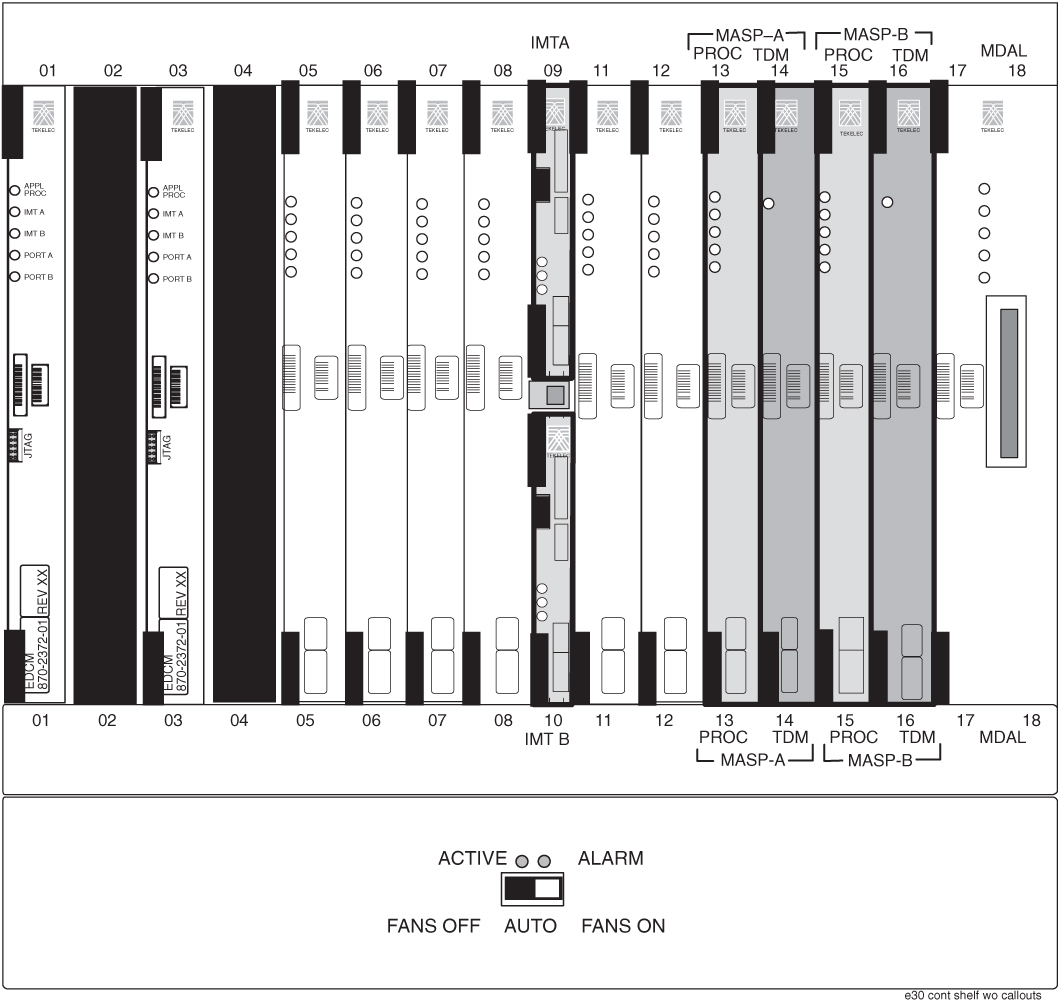
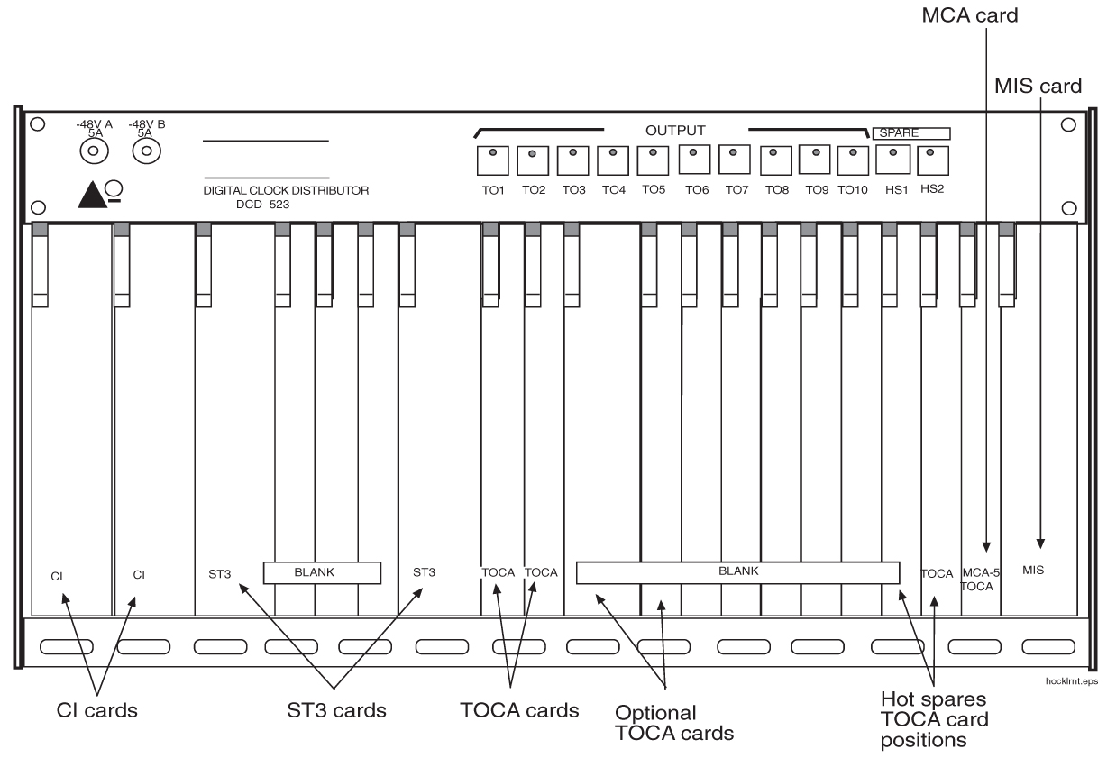
Card Placement

The holdover clock cards must be installed in the positions illustrated in Figure 6-43. Check that the proper cards are installed in the indicated locations.

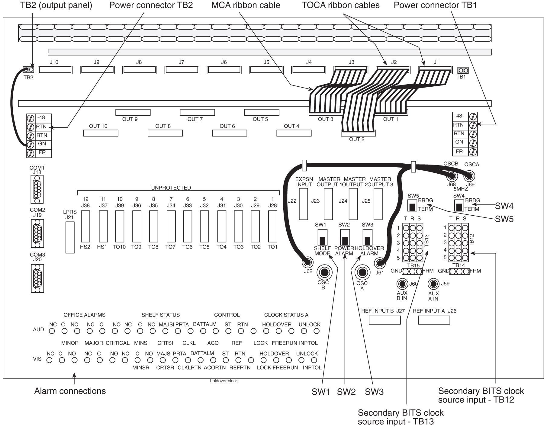
Figure 6-43 Holdover clock


img/c_holdover_clock_installation_im-fig1.jpg

Recommended Tools

Oracle tools should be labeled “Property of ORACLE” with either a press-on Field Tool Identification label or Field Tool Identification wrap.

  • Safety glasses

  • Wire-wrap tool and bit

  • Diagonal cutters

  • Flush cutters

  • Slotted screwdriver with 1/8-inch blade and 8-inch shank, preferred.

  • Phillips screwdrivers, #2 and #3

  • 3/8-inch shrink-wrap

  • Heat-shrink gun (hot air blower)

6.8.1 Output Panel Connections

The following output panel connections are factory installed and should be checked during installation.

TOCA Ribbon Cables

Timing Output Composite Clock Automatic (TOCA) ribbon cable; check to insure that the ribbon cables connecting the holdover clock with the output panel are connected as shown in Figure 6-46. OUT 1 on the holdover clock to J1 on the output panel and OUT 2 on the holdover clock to J2 on the output panel

Note:

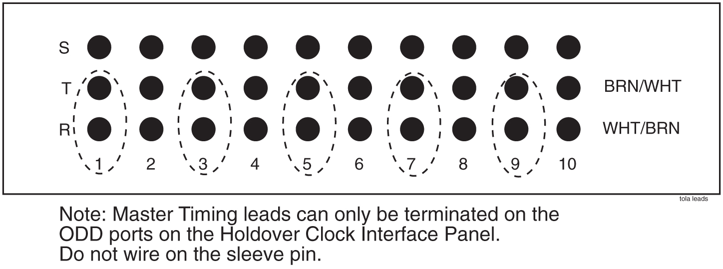
These cables connect the clock outputs from the TOCA cards to the output panel.

TOLA Card

When Using a Timing Output Logic Clock Automatic (TOLA) card; only terminate the clock cable leads to the odd pin positions 1, 3, 5, 7, and 9. Set DIP switch settings to the OFF position. Once switches are set, seat the card.

Figure 6-44 TOLA Source Timing Leads

img/c_output_panel_connections_im-fig1.jpg

Output Panel Frame Ground

Check that the output panel frame ground cable is installed between TB2 on the output panel and an output panel mounting screw, see Figure 6-46.

Note:

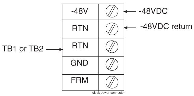
This cable (P/N 690-0009) consists of black #16 AWG and a terminal ring.

Power Connections

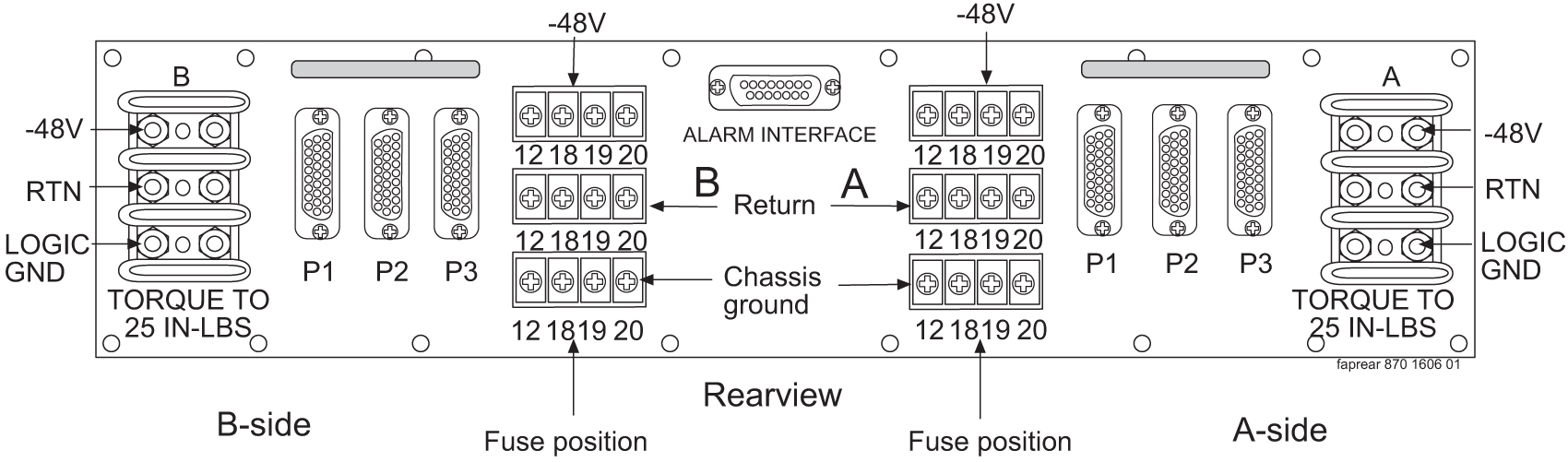
Check that the holdover clock power connections are installed according to Table 6-3 for holdover clock and fuse and alarm panel connections.

See Figure 6-45 and Figure 6-46 for holdover clock connector locations.

See Figure 6-47 and Figure 6-48 for fuse and alarm panel connector locations.

Table 6-3 Holdover Clock Wire Colors and Connections

Holdover Clock Connector Wire Color FAP Connection

TB1 –48VDC

Red

 B side –48VDC #1

TB1 RTN

Black

 B side –48VDC return #1

TB2 –48VDC

Red

 A side –48VDC #1

TB2 RTN

Black

 A side –48VDC return #1

TB1 GND

White

 A side Chassis GND

TB2 GND

White

 B side Chassis GRD

Figure 6-45 Holdover Clock Power Connector


img/c_output_panel_connections_im-fig2.jpg

6.8.2 Holdover Clock Switch Settings

Set the switches on the back of the holdover clock to the following positions, see Clock Input DIP Switch Settings:

  • SHELF MODE (SW1) - ST3 (down)

  • POWER ALARM (SW2) - MAJ (down)

  • HOLDOVER ALARM (SW3) - MAJ (down)

  • REFA (SW4) - TERM (down)

  • REFB (SW5) - TERM (down)

6.8.3 Clock Input DIP Switch Settings

The Dual In-line Package (DIP) switch settings for the Clock Input are:

  • Transmission 1.544 mb -TI (On)

  • Composite Clock - CC (Off)

  • Extended Superframe Format - ESF (On)

  • Bipolar 8Bit Zero Substitution - B8ZS (On)

    Figure 6-46 Holdover Clock and Output Panel, Rear


    img/r_clock_input_dip_switch_settings_im-fig1.jpg

The Fuse and Alarm Panel connections for the Holdover Clock are shown in Figure 6-47.

Figure 6-47 Holdover Clock FAP Connections


img/r_clock_input_dip_switch_settings_im-fig2.jpg

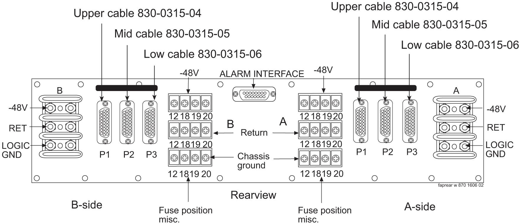
Figure 6-48 Holdover Clock FAP Connections


img/r_clock_input_dip_switch_settings_im-fig3.jpg

6.8.4 Output Panel Connections

The following output panel connections are made during installation.

Connections on the system backplane:

  • First Building Integrated Timing System (BITS) clock cable to Primary BITS connector on J42, and connector J49 on backplane (P/N 850-0330-06 or -07), J49.

  • Second BITS clock cable to the SECONDARY BITS connector J48 on backplane (P/N 850-0330-06 or -07).

Clock Output Connections

The BITS clock cables are used to transmit the clock outputs from the holdover clock output panel to the control shelf backplane.

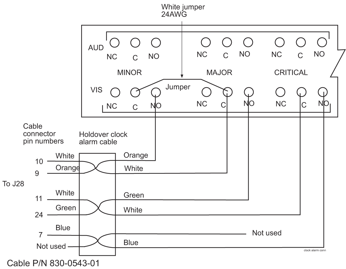
6.8.5 Holdover Clock Alarm Connections

The installation connections are shown in the wiring layouts in Figure 6-50 and Figure 6-51.

A holdover clock alarm cable is used to send alarms from the holdover clock to the control shelf backplane.

  1. Before using the following procedures, loosen the screws holding the clear plastic cover on the back of the holdover clock and remove the cover by lifting it off of the screws
  2. Connect the DB26 connector of the holdover clock alarm cable to the EXTALM connector and CUSTALM 1 connector J35, J66 on backplane (P/N 850-0330-06 or -07) on the system control shelf backplane, see Figure 6-49.
    Secure connector screws.
  3. EXTALM cable connects directly to the Holdover clock.
    The external alarm cable is an optional cable that may go from the EXTALM to a terminal block see Figure 6-50.

    warning:

    Metal points on Printed Circuit Boards conducts -48VDC and can cause shorts, shocks, and damage if not handled properly.

    Figure 6-49 CUST ALM 1 J35 and (not supported) CUST ALM 2 J66 Connectors on Control Shelf Backplane -06 or -07


    img/t_holdover_clock_alarm_connections_im-fig1.jpg

  4. Route the cable up the left side of the control frame, viewed from the rear, over to the miscellaneous frame containing the holdover clock, and down the left side of the miscellaneous frame to the cable tie bar next to the alarm connections, see Figure 6-46.
  5. Tie-wrap the cable to the control shelf cable tie bar at the rear of the shelf.
  6. Pull the slack out of the cable towards the holdover clock.
  7. Dress the cable neatly and tie-wrap to the cable tie bars at the side of the frames.

    Note:

    All cables must be laced (no tie-wraps) to the top traverse arms and above to the cable rack.
  8. Prepare the cable for wire-wrapping by removing the outer insulation of the cable even with a point two inches from the left end of the lower holdover clock cable tie bar.
  9. Apply a 1-1/2-inch length of shrink-wrap tubing.
    Center the tubing on the end of the cable insulation before shrinking tubing with a heat gun.
  10. Wire-wrap a 24-gauge jumper-wire between the minor and major common alarm connector pins as shown in Figure 6-50.
  11. Cut the wires to length, strip, and wire-wrap to the holdover clock at the locations shown in Figure 6-50.

    Figure 6-50 Holdover Clock Alarm Connections


    img/t_holdover_clock_alarm_connections_im-fig2.jpg

  12. Tie-wrap the alarm cable to the lower holdover clock cable tie bar.
  13. Ensure that each tie-wrap strap is cut flush with the tie-wrap head so that no sharp edges are exposed.
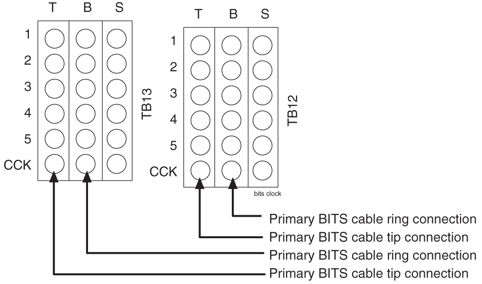
6.8.5.1 BITS Clock Source Cables

This cable connects the holdover clock to the central office Building Integrated Timing System (BITS) clock sources.

  1. Connect the cables to the primary and secondary central office BITS clock sources.
  2. Route the cables to the system’s miscellaneous frame containing the holdover clock.
  3. Route the cables down the right side (viewed from the rear) of the frame.
  4. Pull the slack out of the cable towards the holdover clock.
  5. Dress the cable neatly and tie-wrap to the cable tie bars at the side of the frame.

    Note:

    All cables must be laced (no tie-wraps) onto the top traverse arm and above to the cable rack.
  6. Remove the outer insulation of each cable even with the top of the output panel.
  7. Apply a 1-1/2-inch length of shrink-wrap tubing.
    Center the tubing on the end of the cable insulation before shrinking tubing with a heat gun.
  8. Cut the wires to length, strip, and wire-wrap to the holdover clock at the locations, TB12 and TB13, see Figure 6-51.
    See Clock Input DIP Switch Settings for locations of these connectors.

    Figure 6-51 BITS Clock Source Connections


    img/t_bits_clock_source_cables_im-fig1.jpg

  9. Ensure that each tie-wrap strap is cut flush with the tie-wrap head and turned to the rear of the cable so that no sharp edges are exposed.

6.8.6 Replacing Holdover Clock Rear Cover

When all connections are complete, slide the holdover clock rear cover back onto its mounting screws and then tighten the screws.

6.8.7 Install Holdover Clock Fuses

Install 7.5A (black and white flag) GMT fuses in positions A1 and B1 of the miscellaneous frame fuse and alarm panel that contains the holdover clock.

6.9 Ohms Converter International Market

The ohms converter is used mostly outside of North America. The converter Super Multiple-Interface Cross-Connect (SuperMIX) is a modular device for cross-connecting, patching, and monitoring these digital signal rates:

  • E1 (2.048 Mb/s at 120 Ohms impedance)

The third party SuperMIX modules backplanes will be configured to accommodate a variety of input/output (I/O) termination connector types. Any combination or “mix” of backplanes in one chassis is acceptable. Refer to Telect® “SUPER MULTIPLE-INTERFACE CROSS-CONNECT (SUPERMIX) USER MANUAL” 110339 issue A Rev. 1

Note:

This information is for 120 to 75 ohms only.

Figure 6-52 Miscellaneous Frame with 120 Ohm Converter
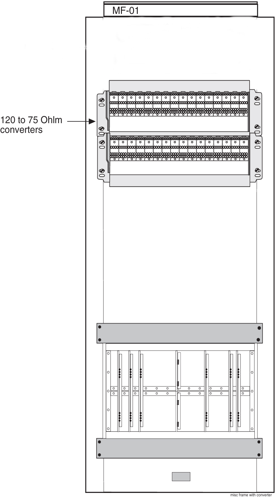

img/c_ohms_converter_international_market_im-fig1.jpg

Note:

Customers may purchase the miscellaneous frame from Oracle.

Table 6-4 Discontinued Legacy Part Numbers

Part Numbers OEM part numbers Description
804-0982-01 or 804-0982-R01 010-0000-2701 Chassis
804-0983-01 or 804-0983-R01 010-2704-1100 Wire-wrap
804-0984-01 or 804-0984-R01 010-2704-1200 Bayonet Connector (BNC)

Note:

There is no compatibility between the discontinued Legacy hardware and the replacement hardware; for reference only. No longer available for new deployment.

Table 6-5 Telect® Replacement System for Cross-Connect Implementation

Manufacturer Part Number Description Description
DNX-2323 84-Term/21-Module, 23" x 5.25" Chassis Chassis
DNX-9324 Wire-Wrap front to Wire-Wrap rear Module Wire-wrap
DNX-9321 Wire-Wrap front to BNC rear Bayonet Connector (BNC)

Note:

Power distribution and replacement ohm converters are to be supplied by the customer.

Figure 6-53 120 Ohms Converter and Shelf


img/c_ohms_converter_international_market_im-fig2.jpg

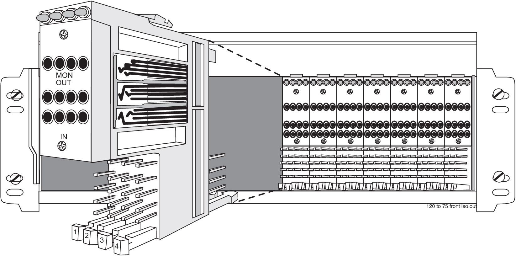
Table 6-6 Physical Conditions

Mechanical

Insertion force

4.17lb (1.9kg) average

Withdrawal force

5.21lb (2.4kg) average

Life

Minimum 20,000 insertion/withdrawal cycles

Environmental

Humidity

To 95% (operating and non-operating)

Moisture Resistance

Per MIL-STD-202F, Method 106E

Salt Spray

Per MIL-STD-202F, Method 101D

Temperature

–40 to 149˚F (–40 to 65˚C) operating

–67 to 185˚F (–55 to 85˚C) non-operating

Thermal Shock

Per MIL-STD-202F, Method 107D

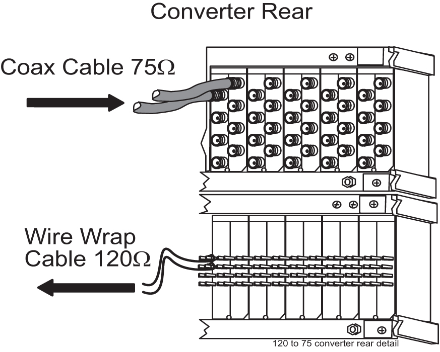
Figure 6-54 120 Ohms Converter Rear


img/c_ohms_converter_international_market_im-fig4.jpg

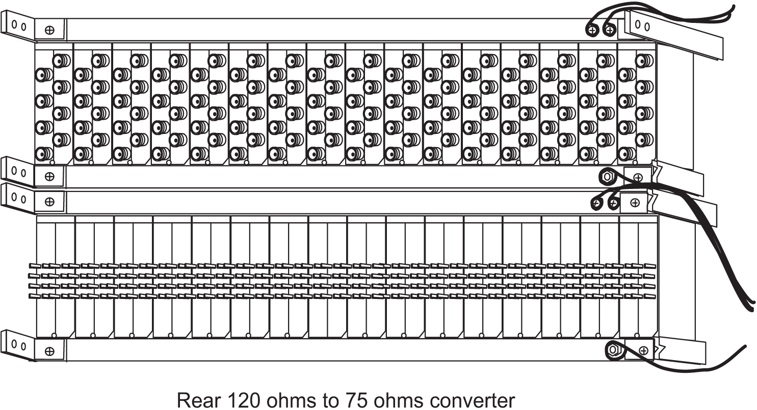
Figure 6-55 Converter Rear Detail


img/c_ohms_converter_international_market_im-fig5.jpg

6.10 Hardware Acceptance

This section is intended for installation and test personnel. This section describes an inspection of the general system installation but does not attempt to cover testing of the system software.

danger:

No commercially AC powered equipment may be used or placed within 7 ft. of –48V equipment. This may create a shock or current loop that can be severely hazardous to personnel and equipment.

Hardware operational testing is designed to verify the functionality of the finalized construction of the hardware at the customer site. The demarcation line for the testing is up to and including the patch panel directly connected to the system. The ability to route traffic through this system is verified using a Message Generator Traffic Simulator (MGTS). All cabling, alarm output, clock input, and other Oracle equipment is also verified operational per the Hardware Operational Test Manual provided with the test equipment.

Caution:

All personnel associated with the installation of this system must adhere to all safety precautions and use required protection equipment, to avoid the possibility of injury to personnel, service degradation, and/or service interruption.

Caution:

This is a redundant system, to allow service during normal maintenance. When repairs require a total power disconnect, both input supply sources must be disconnected. This will cause service interruption and takes down the system.

The customer frame layout is site specific, however the most typical frame layout is constructed with Extension Frames to the right of the Control Frame when viewed from the front. The OAP Frame is normally on the left of the Control Frame. Other frames (Miscellaneous and other support or feature specific frames) are lined up to the left of the Control Frame. General Inspection.

Procedure — Perform General Installation Inspection

Verify the following:

  1. All items listed in the Equipment Specification have been installed.

  2. Cabling is neatly installed and the labels are correct and easily readable.

  3. Power cabling does not run through a cable rack.

  4. Power cabling is not routed together with any other cables and has at least six inches of clearance.

  5. Racks have Nomex paper between the rack and any power cables that would otherwise touch the rack.

  6. The main central office ground is correctly labeled and has the “Do Not Remove” tag installed on the central office grounding bar. No “double lugs” are allowed. Any bolt through a nut must show at least two threads beyond the nut but no more than four threads should be showing.

  7. The –48VDC power feeds are correctly labeled at the central office power distribution panel. There should be an A feed and a B feed for each frame.

  8. The –48VDC returns are correctly labeled. There should be an A return and a B return for each frame.

  9. Frames are level.

  10. Earthquake bracing, if any, is properly installed.

  11. Adequate floor clearances have been maintained.

  12. Rear panels are installed.

  13. Cable connections are tight at the backplane connections.

  14. Cable sheets are properly marked and located in door pocket.

  15. All documentation has been received and is available.

  16. Terminals and printers connected to the system are operational.

  17. Data cartridges have been received and are properly stored.

  18. Any attached modems are operational.

  19. Any attached MAUs are operational with power indicator on.

  20. Shipping container is properly packed with ramp and frame dollies prepared for shipment.

  21. The area is clean and unused material has been properly disposed of.

6.11 –48VDC Power Source

This section verifies that the –48VDC Power Source has been labeled and connected correctly to the corresponding system frame's Fuse and Alarm Panels (FAPs). Your system may not include all of the frames described.

danger:

No commercially AC powered equipment may be used or placed within 7 ft. of –48V equipment. This may create a shock or current loop that can be severely hazardous to personnel and equipment.

warning:

Do not carry exposed metal keys or tools in pockets or on belts when working on or around electronic equipment. Do not wear metal rings, watches, or jewelry on wrists or hands when working on any electronic equipment or other related electrostatic sensitive components. Always wear a wrist strap or other electrostatic protection when handling printed circuit cards and other electrostatic sensitive devices.

warning:

Before beginning any of the following procedures, ensure that all breakers that provide power to the system are open.

warning:

Before performing the following procedures do the following:
  • Ensure that no power is being provided to the system from the –48VDC power source, such as a power board

  • Ensure that no circuit cards are installed in the shelves

  • Remove all fuses from the fuse and alarm panels

  • Recheck wiring and connections for proper polarity

Caution:

All personnel associated with the installation of this system must adhere to all safety precautions and use required protection equipment, to avoid the possibility of injury to personnel, service degradation, and/or service interruption.

Caution:

This is a redundant system, to allow service during normal maintenance. When repairs require a total power disconnect, both input supply sources must be disconnected. This will cause service interruption and takes down the system.

6.11.1 Verify -48VDC

The following procedure verifies –48VDC.

  1. Turn on breaker, or insert fuse for control frame A side –48VDC power source.
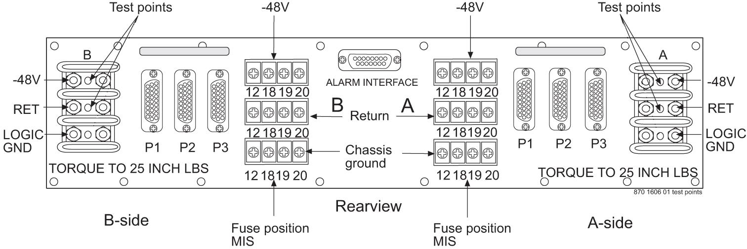
  2. Check for nominal –48VDC at the control frame fuse and alarm panel A side test point.

    For test points used see Figure 6-56 and Figure 6-57.

    Note:

    Input voltage range is -40 VDC to -57.5 VDC.

    Figure 6-56 Test Points 1U FAP (P/N 870-2804-01)

    img/r_fuse_and_alarm_panel_1u_im-fig2.jpg

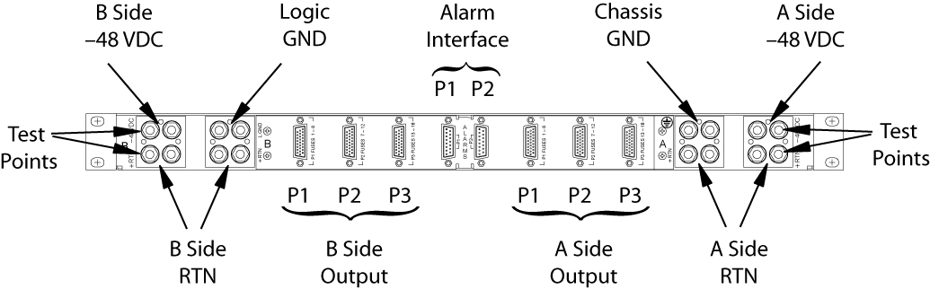
    Figure 6-57 Test Points 3U FAP (P/N 870-2320-03)


    img/c_48vdc_power_source_im-fig2.jpg

  3. Repeat 1 and 2for the control frame B side –48VDC power source.
  4. Repeat 1 and 2for each –48VDC A side and B side power source for all extension and miscellaneous frames.
This completes the procedure.