3 General Installation Information
3.1 Hardware Operational Testing
Hardware operational testing is designed to verify the functionality of the finalized construction of the hardware at the customer site. The demarcation line for the testing is up to and including the patch panel directly connected to the system. All cabling, alarm output, clock input, and other equipment is also verified operational per the Hardware Operational Test Manual provided with the test equipment..
attention:
If components arrive in containers that might have been subjected to extreme temperatures or variations in humidity (such as air transport), allow 6 hours for the components to acclimatize to your site conditions before operating.3.2 Components Overview
The name, function, and part number(s) of the most current EAGLE components are listed in alphabetical order. For a detailed hardware description, refer to Hardware Reference. For more history and part numbers of these components, refer to LED Information.
Table 3-1 EAGLE Components
| Acronym | Name | Function |
|---|---|---|
|
Air Management Card |
Filler card without electrical connections |
|
|
Clock Interface Card (Holdover Clock) |
Input signal redundancy |
|
|
Expandable Database Communications Module |
IP connectivity |
|
|
Database Service Module |
Large-capacity SCCP database |
|
|
E5-APP-B |
EAGLE Application B Card |
General-purpose application server (AS) that offers high transaction rates with low latency |
|
E5-E1T1 |
E5-E1/T1 Interface Module |
Single slot card providing eight trunk terminations processing up to 32 signaling links of configurable channelized E1 or T1 connectivity |
|
E5-ENET |
E5-ENET Interface Module |
One or more Ethernet interfaces |
|
E5-SM4G |
Database Service Module |
SCCP Database |
|
E5-STC |
E5-ENET Interface Module |
IP connectivity |
|
E5-TSM |
Translation Service Module |
GLS functionality |
|
HIPR2 |
High-Speed IMT Packet Router 2 Module |
Provides Interprocessor Message Transport (IMT) bus continuity for all cards connected to the IMT bus at a rate of 2.5 Gbps for large systems |
|
Link Interface Module |
Provides specific SS7 interfaces |
|
|
MCA |
Matrix Controller Automatic (Holdover Clock) |
Controls output protection switch matrix |
|
MIS |
Maintenance Interface System Card (Holdover Clock) |
Provides alarms output to system control shelf |
|
MPS |
Multi-purpose Server |
Database/reload functionality to various applications |
|
SLIC |
Service and Link Interface Card |
Single/multi-use card that runs multiple applications |
|
Timing Output Composite Automatic (Holdover Clock) |
Clocks outputs (TO1 and TO2) for A and B through the system control shelf |
Note:
For the complete list of cards supported by EAGLE Release 47.0, see Hardware Reference Guide.3.3 Card Installation and Replacement
The frame arrives configured with the cards in place. After installing the frame in its final location, remove all cards prior to powering up the frame. Reinstall all cards in the control shelf, extension shelves, and other frames carefully to avoid possible faulty connections. When installing a card, be aware of possible electrostatic discharge or shorts.
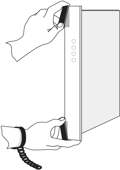
warning:
Always wear a wrist strap or other electrostatic protection when handling electronic cards or electrostatic sensitive devices.Cam-out/lock-in levers on the front edge of the card assist in insertion and removal of the card. Grasp the card at the top and bottom, as shown in the figure below, and slide the card into the appropriate slot. Using the card slot guides in the shelf, slide the card into the shelf until the connectors on the card seat with the connectors on the backplane. Press both tabs in until they lock the card in place. To ensure proper seating, the levers must be held in the release position until the locking tabs can engage with the upper and lower flange on the shelf. Once the locking tabs on the levers engage the shelf plane, the tabs are pressed to the card faceplate, and must be flush with the faceplate when the card is completely seated.
Figure 3-1 Removing an EAGLE card
Part number, LEDs, text and bar code (CLEI and serial number) are located on the faceplate of each card. The cards in the frames are configured with specific functions and services.
3.4 Labeling
This section provides general labeling instructions for cables, frames, shelves, and fuse and alarm panels.
3.4.1 Cable Labeling
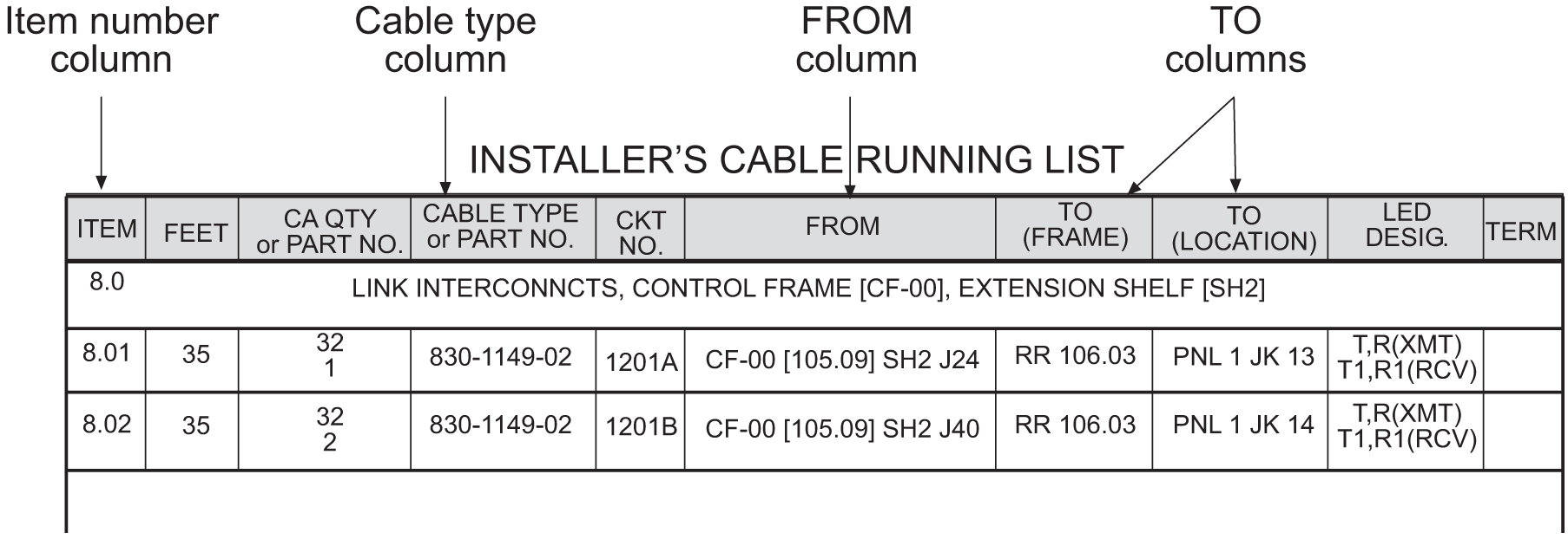
Before installing, use this procedure to label the cables to ensure connection to the proper ports and ease of future maintenance.
Tools
-
Installer’s Cable Running List
-
All cables listed in Installer’s Cable Running List
-
Any non-Oracle cables
-
Cable labels (including blank labels for non-Oracle cables)
-
Fine point marker
3.4.2 Fuse and Alarm Panel Labeling
EAGLE frames arrive from the factory with labels in place. If a frame is assembled at a site, a labeling kit may be necessary.
3.4.2.1 Label Kit for FAP (P/N 870-2804-001)
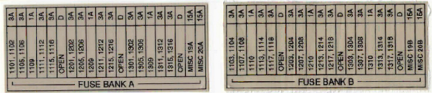
- Press the sticky side of the label into the silk screened area on the front of the drip tray located just below the Fuse and Alarm Panel for the specific frame. Place the label marked FUSE BANK A on the left side of the drip tray faceplate. The label marked FUSE BANK B is placed on the right side of the drip tray faceplate.
Figure 3-3 Control Frame Fuse Label
3.4.2.2 Label Kit for FAP (P/N 870-1606-xx/870-2320-xx)
Label Kit (P/N 870-1915-02) contains large sheets of die-cut stick-on labels for the appropriate frames. There are three large sheets of die-cut, stick-on labels:
-
Sheet (P/N 658-0604-01) is for FUSEBANK A, CONTROLFRAME through EF-04
-
Sheet (P/N 658-0604-02) is for FUSEBANK B, CONTROLFRAME through EF-04
-
Sheet (P/N 658-0604-03) is for MISCFRAME
Also included in the Label Kit (P/N 870-1915-02) are smaller die-cut stick-on labels for different fuses relating to different amps and individual pieces of site-specific equipment; these are to be pressed into fuse OPEN spaces.
- The labels must be pressed into place on the front faceplate of the correct frame.
The left side of the faceplate is marked A and the right side of the faceplate is marked B.
Figure 3-4 FAP, Fuse Label Kit (P/N 870-1915-02)
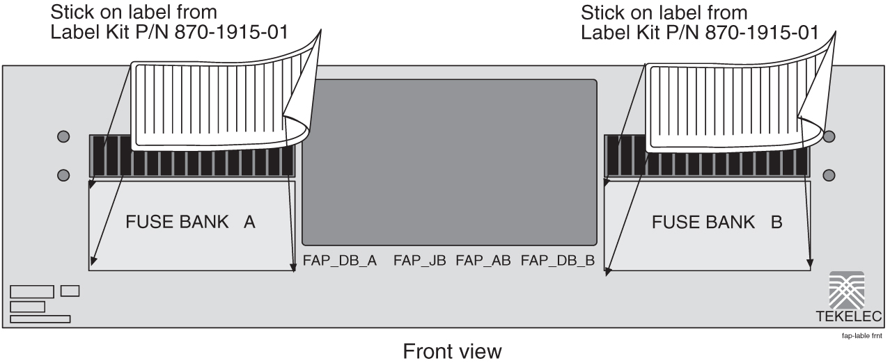
The label designates CONTROLFRAME or EF-00 through EF-04.
There are also labels for the MISCFRAME.