2 Safety Information
This chapter lists important safety information to protect personnel and equipment.
2.1 General
These icons and text throughout this manual are to alert the reader, to assure personnel safety, to minimize service interruptions, and to warn of potential equipment damage.
Table 2-1 Admonishments
|
|
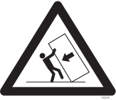
TOPPLE/DANGER: (This icon and text indicate the possibility of personnel injury and equipment damage.) |
|
|
DANGER: (This icon and text indicate the possibility of personnel injury.) |
|
|
WARNING: (This icon and text indicate the possibility of equipment damage.) |
|
|
CAUTION: (This icon and text indicate the possibility of service interruptions.) |


warning:
All personnel associated with the installation of these systems must adhere to all safety precautions and use required protection equipment to avoid the possibility of injury, equipment damage, service degradation, or service interruption.warning:
Some procedures may interrupt service. When possible, perform maintenance during low traffic and database provisioning periods, such as the maintenance window.2.2 Frames
topple:
Always read and understand instructions thoroughly and completely before working on, moving, raising or lowering the frame, any portion of the frame, attachments to the frame, or equipment.topple:
Never try to unpack any frame from the shipping container without at least two people to steady any movement of the frame and related components. At least two people are required to safely move and position a frame into place.topple:
Never pull out the shelf of a frame that is not anchored properly. Systems with sliding shelves must be securely anchored to the floor and to the overhead cable racks. Extending a shelf without correctly anchoring the frame can cause the frame to topple and endanger personnel and damage equipment.topple:
Frames are required to be attached to over-head ladder-racks before shelves are extended.DANGER:
Moving an application server chassis requires two people. Each chassis weighs approximately 25 kg (55 lbs) and may cause injury or damage to internal components due to shock and vibration if not handled properly.warning:
Before drilling holes in any flooring, verify with facilities personnel that the area is free of gas or water pipes, ventilation plenum, and electrical wiring conduits.warning:
Finger-tighten nuts on threaded rods inside the frames above the raised floor before finger tightening the nuts below the raised floor.Caution:
Frame ground. Do not “double lug”: The practice of using one bolt through a lug and the ground bar, and through another lug on the other side of the ground bar, held in place by one nut.A bolt through any nut must show at least two threads beyond the nut.
2.3 Power
danger:
Do not use or place commercially AC-powered equipment within 7 ft. of –48V equipment. Close proximity can create a shock or current loop that is severely hazardous to personnel and equipment.warning:
The intra-building port(s) of the equipment or subassembly is suitable for connection to intra-building or unexposed wiring or cabling only. The intra-building port(s) of the equipment or subassembly MUST NOT be metallically connected to interfaces that connect to the Outside Plant (OSP) or its wiring. These interfaces are designed for use as intra-building interfaces only (Type 2 or Type 4 ports as described in GR-1089-CORE, Issue 4) and require isolation from the exposed OSP cabling. The addition of Primary Protectors is not sufficient protection in order to connect these interfaces metallically to OSP wiring.warning:
The power (-48 VDC) and return connections of Fuse and Alarm Panels (FAP) 870-0243-08 and 870-1606-xx are physically reversed at the input terminal.warning:
Before testing -48VDC power source:-
Ensure that no power is being provided to the system from the –48VDC power source, such as a power board
-
Ensure that no circuit cards are installed in the shelves
-
Remove all fuses from the fuse and alarm panels
-
Recheck wiring and connections for proper polarity
warning:
Always install an isolator pad between the frame and ground. Oracle frames are shipped with isolator pads to completely isolate the frames from ground. If a non-Oracle frame is used, an isolator pad must be provided.warning:
Frames with HCMIM cards require 60A breakers, ELAP frames use 30A and 60A breakers, and EPAP frames use 30A breakers. Existing frames that are fused at 40A can be upgraded to support 60A with a FAP upgrade kit.warning:
Verify that all breakers for application servers are set to the OFF (O) position. An application server chassis is redundantly powered from both A and B -48VDC buses. Ensure that both the circuit breaker supplying A power to the chassis and the circuit breaker supplying B power to the chassis are turned OFF by measuring the voltage with a VOM on the cable that connects the chassis to its breakers. Both A and B power LEDs on the front panel of the chassis should be OFF.Caution:
Redundant systems allow service during normal maintenance. When repairs require a total power disconnect, both input supply sources must be disconnected. This causes service interruption and takes down the systems.Caution:
This equipment has a connection between the earthed conductor of the DC supply circuit and the earthing conductor.Caution:
The Branch Circuit Overcurrent Protection shall be rated at 48V minimum and 40A maximum.Caution:
Install equipment in restricted access areas in accordance with articles 110-16, 110-17, and 110-18 of the National Electric Code, ANSI/NFPA 70.Caution:
Incorporate a readily accessible approved disconnect device in the field wiring.Caution:
Connect to a reliably grounded SELV source that is reliably earthed and electrically isolated from the AC source.Caution:
Use only listed closed-loop connectors for connection to the power supply.2.4 Electrostatic Discharge
danger:
Do not wear metal, chains, rings, watches, or jewelry or carry exposed metal, keys, or tools in pockets when working on system equipment or other related electrostatic-sensitive components.danger:
Always wear a wrist strap or other electrostatic protection when handling printed circuit cards and other electrostatic-sensitive devices.warning:
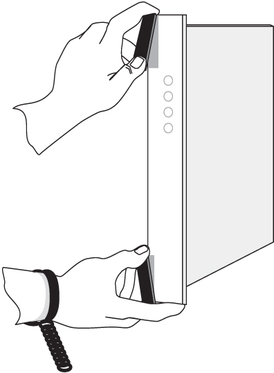
Observe proper ESD procedures when handling the application server chassis. Always wear an ESD wrist strap connected to a grounded bench or frame.warning:
Use the antistatic wrist strap connected to the wrist strap grounding point on the frame when performing these procedures.warning:
Do not leave or allow unused metal objects, such as screws or washers, to remain anywhere within the equipment. Remove all unused material from the equipment.warning:
Do not allow any metal shavings to remain in the equipment area. Shavings may occur from over tightened screws or bolts. These small metal particles are hazardous to electronic equipment. Be careful not to over tighten screws or bolts.warning:
Do not use tie wraps on or above the top traverse arms on a frame. Always trim tie wrap flush and turn the trimmed tie wrap to the rear of the cable. Contact the Site Supervisor for site-specific customer information.2.5 Components
warning:
If components arrive in containters that might have been subjected to extreme temperatures or variations in humidity (such as air transport), allow 6 hours for the components to aclimatize to your site conditions before operating.warning:
Metal points on Printed Circuit Boards conducts -48VDC and can cause shorts, shocks, and damage if not handled properly.Caution:
New CPCI cards may have a small plastic cover over the screws or the alignment ejector pins. Remove and discard these plastic covers. If inserting the cards takes an excessive amount of force, check for obstructions. Forcing the card into a slot may damage the ejector handle or pin.Caution:
In EAGLE, make sure that the DCM card is inserted into the correct odd numbered slots. In IP7 Secure Gateway systems, there are no slot provisioning requirements. Cards may be provisioned in any slot where they physically fit except for the HMUX and MAS dedicated card slots.Caution:
After the frame has been shipped or moved, remove all cards prior to applying power. Carefully reset cards to avoid possible faulty connections.To remove or install a card, use the module locking tabs at the top and bottom of the card faceplate. See to Figure 2-1.
Figure 2-1 Removing a Card
Caution:
Do not impact the faceplate in order to mate the connectors. Any impact to the card’s faceplate can damage the faceplate, the pins, or the connectors.Caution:
Be sure to install the fan assembly 890-0001-04 before installing the HCMIM card.Caution:
Before powering up the fans, ensure that the shelf directly above the fan does not contain any empty slots. Install an air management card in any empty slots to ensure proper air flow. These filler cards have no electrical connection to the system.Caution:
Do not form FAN POWER cables with LIM cables.