4 Frames and Shelves
4.1 Unpacking
danger:
At least two people are required to safely move and position the frames. Read and understand this procedure completely before continuing.-
Before opening any shipping container, inspect it for evidence of damage during shipment. Report any damage to the carrier for investigation and possible claims. Also report any damage to the Oracle site supervisor.
-
Check the packing slips against the equipment specification list for this installation site. Report any discrepancies to the My Oracle Support (MOS).
-
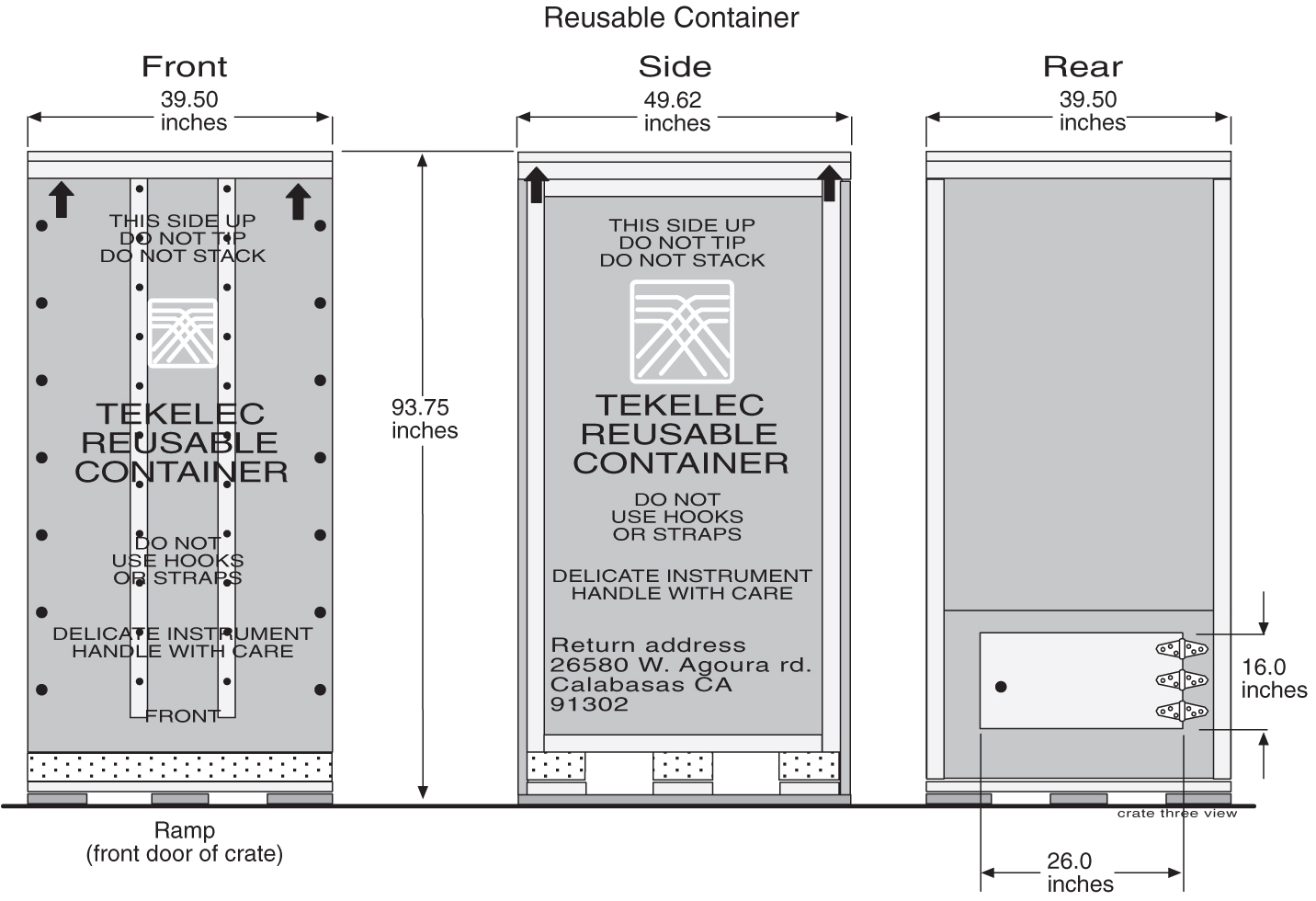
Use the 9/16 inch wrench to remove all of the bolts that hold the front to the shipping container. Do not discard the bolts. Remove the shipping container front panel. Place the bolts into the bag provided inside the shipping container. The shipping container will be returned before and separately from the dolly holding the frame in place. The dolly is used to move and position the frame. Save all bolts and hardware.
Figure 4-1 Shipping Container for Heavy Duty Frame
-
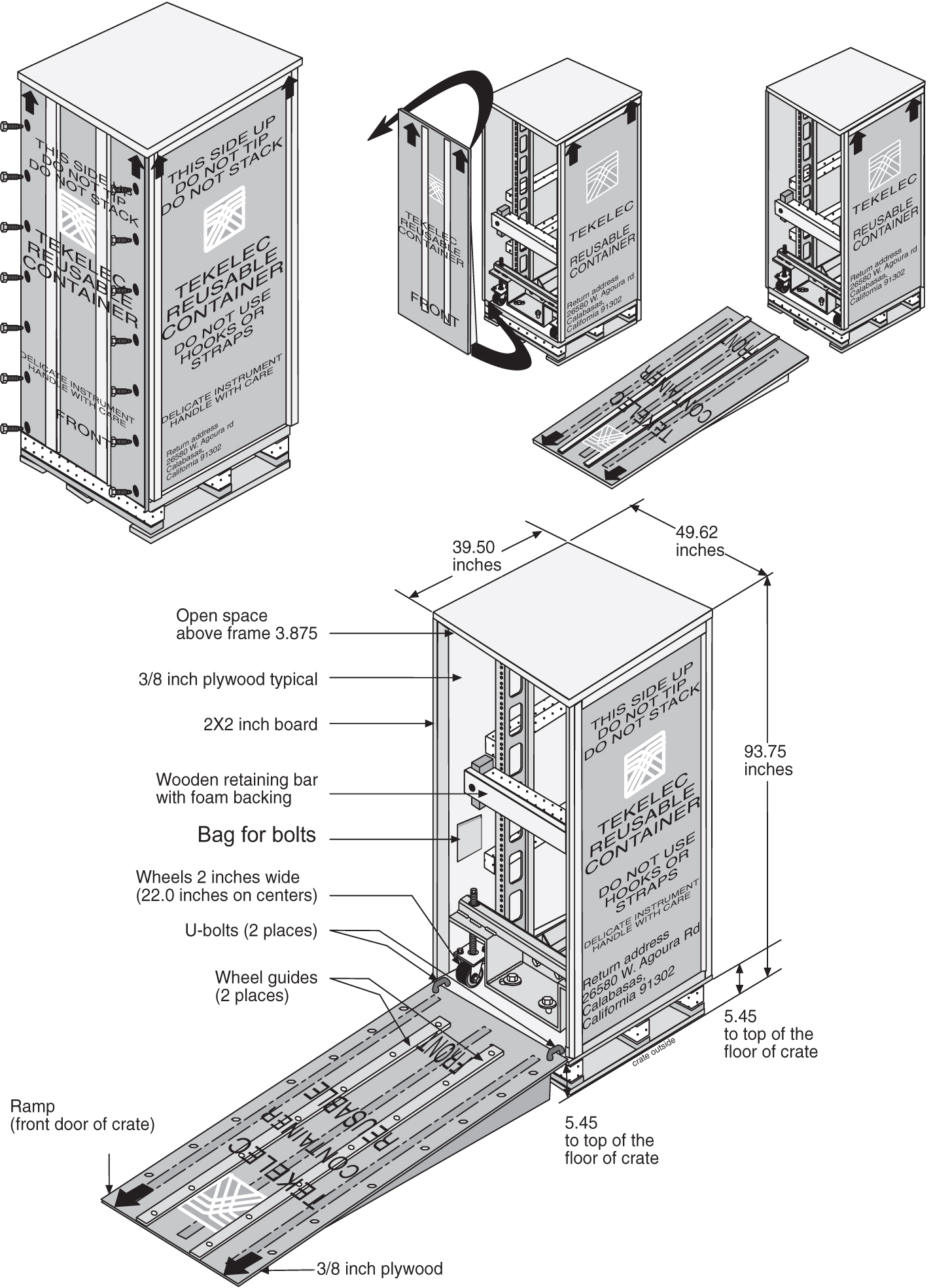
Use the front panel of the shipping container as a ramp to remove the frame from the shipping compartment. Place the ramp against the front of the container making sure the angle side is up and slants away from the frame in the container. Place the ramp against the front edge of the shipping container. Insert the U-bolts in the holes to secure the ramp support and container together.
-
Open the rear door of the shipping container
Figure 4-2 Shipping Container for Heavy Duty Frame
-
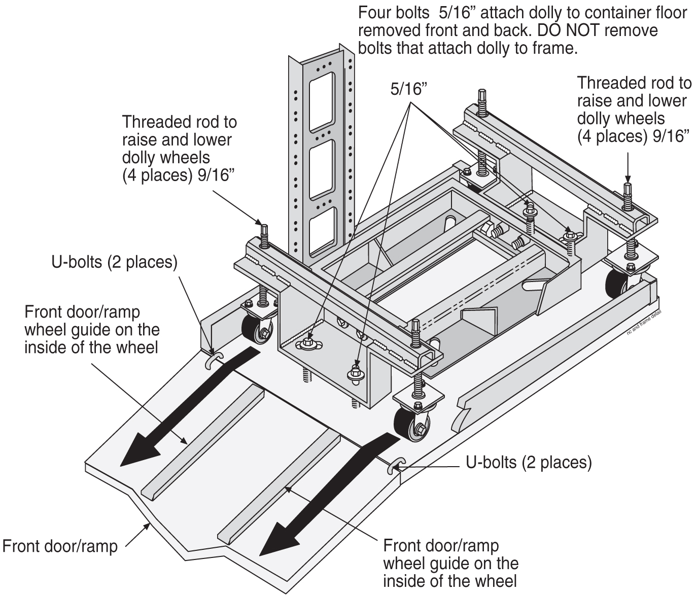
Use the 9/16 inch wrench to unbolt the wooden retaining bar across the front of the frame. Do not discard the retaining brace or the bolts. At this time Do not remove the bolts holding the dolly to the frame. Refer to Figure 4-3.
-
At least two people are required any time a frame is moved. Use the 9/16 inch wrench to turn the threaded rod counter clockwise to lower the wheels of the dolly and to raise the frame and dolly enough to clear the front edge of the shipping container, approximately 1-1/2 inches. The threaded bolts must be turned at the same time by two people, one in the front and one in the rear to avoid making the frame tilt.
-
Only raise the frame high enough to clear the angle created by the front ramp. When the frame and dolly have been raised enough to clear the angle created by the front ramp, slowly and carefully roll the frame out of the shipping container.
Note:
For clarity, the frame in the shipping container is shown without system hardware components.Figure 4-3 Shipping, Detach Dolly Heavy Duty Frame
-
With a minimum of two people, carefully move the frame to the next location.
-
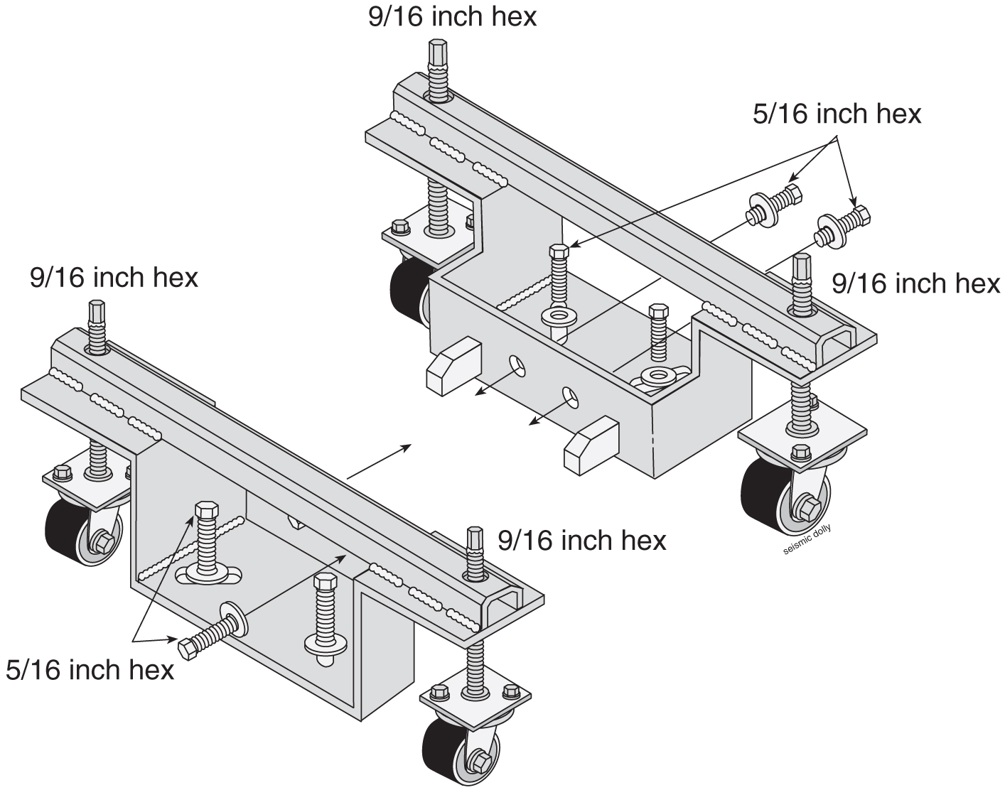
At the correct site location, turn the threaded rods counter clockwise to lower the frame by raising the wheels of the dolly. Again two technicians must turn the threaded rods at the same time avoid tilting. Refer to Figure 4-4 for the location of the threaded rods attached to wheels.
Figure 4-4 Heavy Duty Frame Dolly
-
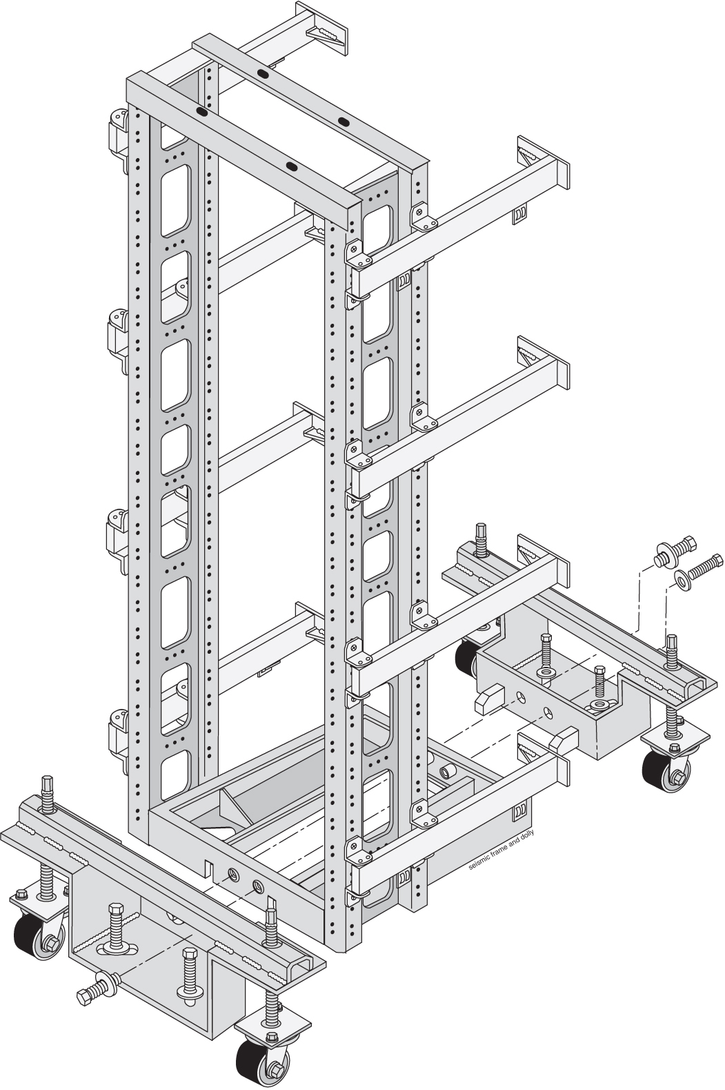
Remove the bolts, front and rear, that attach the dolly to the frame. Refer to Figure 4-5.
Note:
For clarity, the Frame is shown without system hardware components.Figure 4-5 Heavy Duty Frame with Dolly
-
When the dollies are removed from the frame after the frame has been moved to a permanent location, the dollies are returned separately from the shipping container.
-
Inventory the shipment to make sure that all items listed on the pick list have been received in good condition. Report any discrepancies or damaged equipment to the My Oracle Support (MOS).
-
Do not allow the empty shipping containers to become a safety problem or a fire hazard. Contact the site supervisor for specific instructions. Dispose of leftover packaging materials according to local recycling procedures.
-
Follow this procedure when opening all similar shipping containers.
Use this procedure if the shipping container is to be returned to Oracle.
4.2 Floor Preparation
This section describes how to lay out the floor plan for on-site flooring, and how to prepare a raised floor or a concrete floor for frame installation. For specific types of flooring refer to Concrete Floor or Anchoring to Overhead Rack of Heavy Duty Frame .
General Floor Preparation
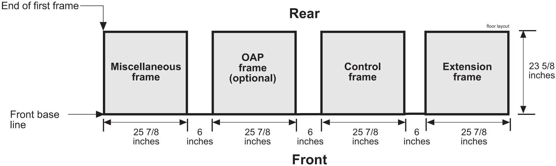
The floor layout for the frame is site specific. The most typical frame layout is constructed with Extension Frames to the right of the Control Frame when viewed from the front. The OAP Frame (if applicable) is typically on the left of the Control Frame. Miscellaneous Frames and other support or feature specific frames are lined up to the left of the Control Frame. Refer to the figure below.
Typically, the aisle space from the rear of the frame to the front of other frames or equipment is three feet. The end of the frame layout must be no less than 12 inches from other telco frames.
Note:
The recommended minimum aisle spacing is 2-1/2 ft. (75 cm) front and rear.Figure 4-6 Typical Frame Layout

4.2.1 Recommended Tools
Oracle tools should be labeled “Property of ORACLE” with either a press-on Field Tool Identification label Field Tool Identification wrap.
-
Safety glasses
-
Chalk-line, with chalk
-
Fiberglass tape measure
-
Felt tip pen
-
Isolation sheet (template in mounting hardware kit) to mount one frame
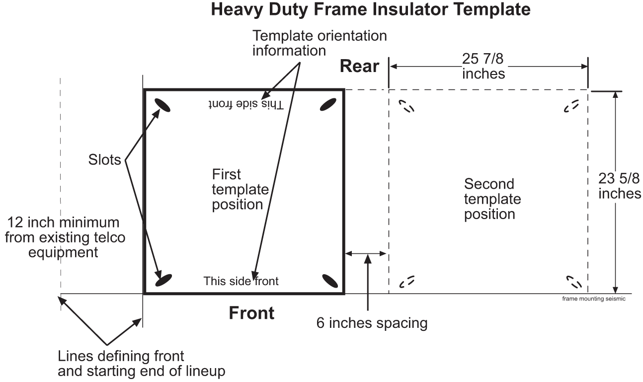
- Use the floor plan provided with the engineering site file specifications to mark the front base line and the borders of the first frame with the chalk line (refer to Figure 4-7).
Figure 4-7 Typical Floor Layout for Frames
- Use the felt tip pen to mark the anchor location in the middle of each slot and corners for each successive frame.The next section describes how to prepare a raised floor for frame installation.
Figure 4-8 Isolation Sheet/Template for Frame
4.2.2 Raised Floor
This section describes how to prepare a raised floor for a heavy duty frame installation with anchors. Always get permission from facility personnel before drilling holes.
4.2.2.1 Recommended Tools
Oracle tools should be labeled “Property of ORACLE” with either a press-on Field Tool Identification label or Field Tool Identification wrap.
-
Safety glasses
-
Rotary impact drill
-
18 mm masonry drill-bit
-
1 inch drill-bit (hole saw)
-
Extension cord
-
Vacuum cleaner (an approved, industrial type, that prevents escaping dust particles that may contaminate electronic equipment)
-
Masking tape
-
Fiberglass tape measure
-
Isolation sheet (in mounting hardware kit P/N 840-0092-01)
-
Subfloor marking tool
-
Ear protectors
-
Felt tipped marking pen
-
File
-
Mounting hardware kit (furnished with each heavy duty frame)
The procedure for preparing raised flooring is highly site specific. For more information, refer to the site specific specification as per the Method Of Procedure (MOP) for the particular installation.
warning:
Before drilling holes in any flooring, verify with facilities personnel that the area will support a loaded frame and is free of gas or water pipes, ventilation ducts, electrical wiring conduits, or any other items that may be damaged. If the hole is drilled at an angle the anchor and frame will not come together properly. After marking anchor locations, remove the tiles and take them to an approved location for drilling. Do not drill tiles in the equipment area.4.2.2.3 Heavy Duty Frame Anchoring
This section describes how to anchor a frame on a raised floor.
- Replace tiles if necessary.The following figure shows a heavy duty frame installed on a raised floor.
Figure 4-9 Raised Floor Installation Elements
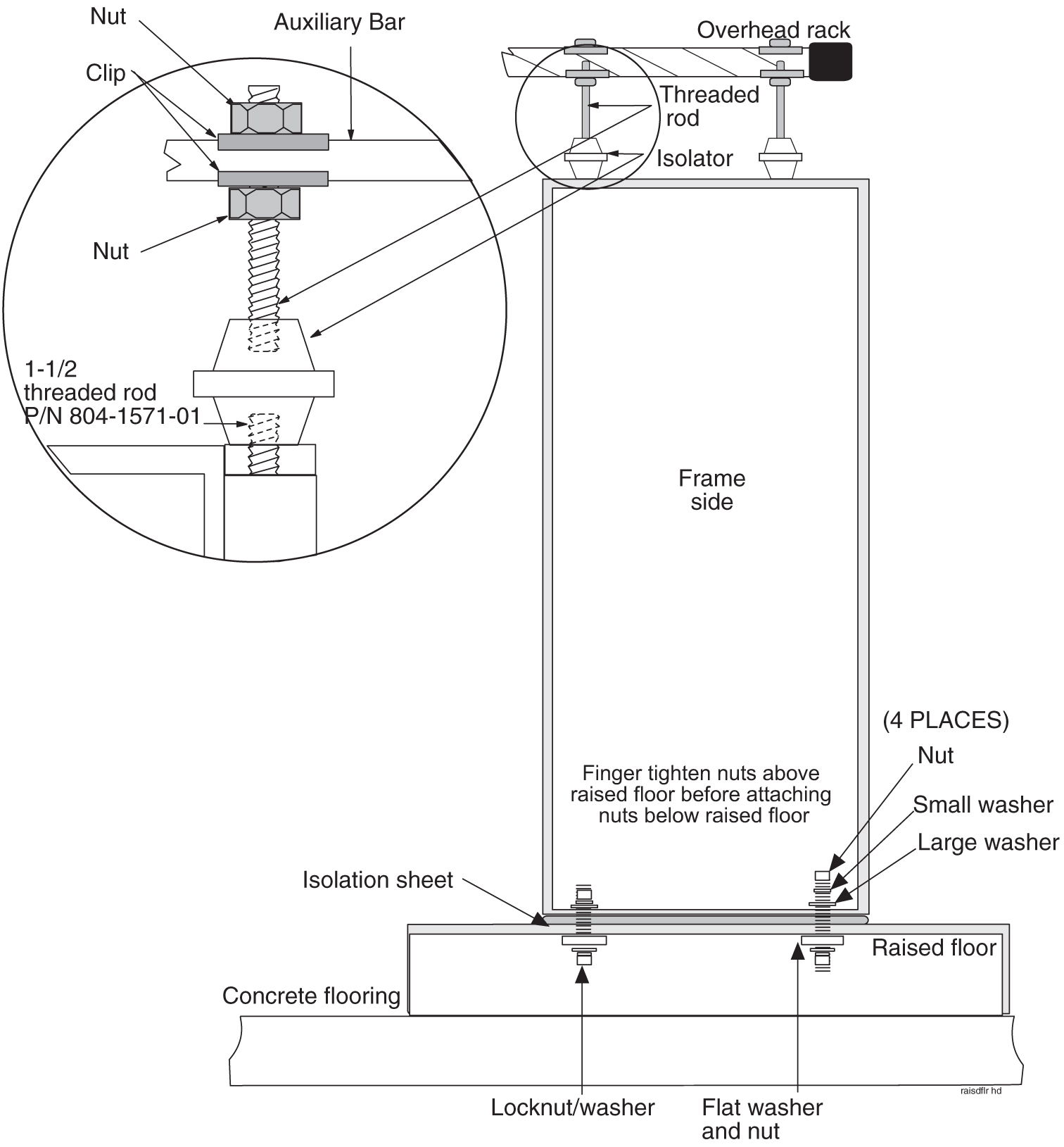
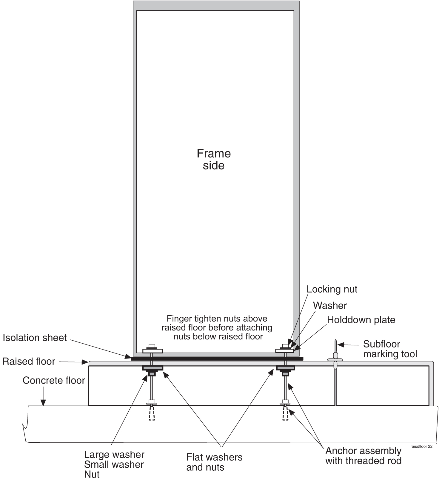 Refer to Figure 4-10 when installing the heavy duty frame on a raised floor using overhead racks, flat washers, and nuts, Cable Rack Mounting Kit.
warning:
Finger tighten nuts on threaded rods inside the frames above the raised floor before tightening the nuts below the raised floor.Figure 4-10 Raised Floor With Overhead Rack
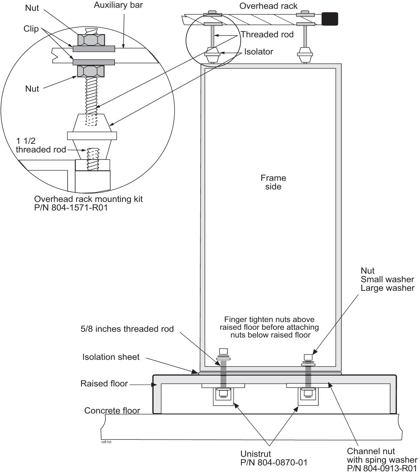
 Refer to Figure 4-11 when installing the heavy duty frame on a raised floor using Unistruts and the Cable Rack Mounting Kit (P/N 804-0219-01).
warning:
Finger tighten nuts on threaded rods inside the frames above the raised floor before tightening the nuts below the raised floor.Figure 4-11 Raised Floor Installation With Unistrut
warning:
Finger tighten nuts on threaded rods inside the frames above the raised floor before tightening the nuts below the raised floor.
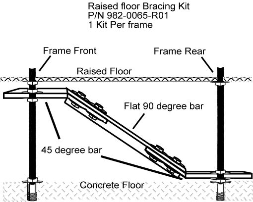
4.2.2.4 Raised Floor Earthquake Bracing
This section describes how to install earthquake bracing to a raised floor installation. Bracing is required in earthquake zones 3 and 4 when installing a frame onto a raised floor with a spacing of 1.5 feet or more between the raised floor and the subfloor.
- Assemble the Earthquake Brace by securing the 45 degree bar steel pieces to the flat 90 degree bar.
Use the Earthquake Brace Kit P/N 982-0065-R01.
Figure 4-12 Earthquake Bracing
4.2.3 Concrete Floor
This section describes how to prepare a concrete floor for heavy duty frame installation. Always get permission from facility personnel before drilling holes. Before drilling holes in any flooring, verify with facilities personnel that the area is free of gas or water pipes, ventilation ducts, electrical wiring conduits, or any other items that may be damaged.
4.2.4 Recommended Tools
Oracle tools should be labeled “Property of ORACLE” with either a press-on Field Tool Identification label or Field Tool Identification wrap.
-
Extension cord
-
Vacuum cleaner (an approved, industrial type, that prevents escaping dust particles that may contaminate electronic equipment)
-
Fiberglass tape measure
-
Felt tipped marking pen
-
Mounting hardware kit (furnished with each heavy duty frame)
Caution:
All personnel associated with the installation of this system must adhere to all safety precautions and use required protection equipment to avoid the possibility of injury to personnel, service degradation, and/or service interruption.Caution:
This is a redundant system to allow service during normal maintenance. When repairs require a total power disconnect, both input supply sources must be disconnected. Disconnection will cause service interruption and take down the any system.warning:
Before drilling holes in any flooring, verify with facilities personnel that the area is free of gas or water pipes, ventilation and electrical wiring conduits.
The personnel must have a thorough knowledge of telecommunication installation specifications and procedures.If the holes are drilled at an angle the anchor and frame will not come together properly.
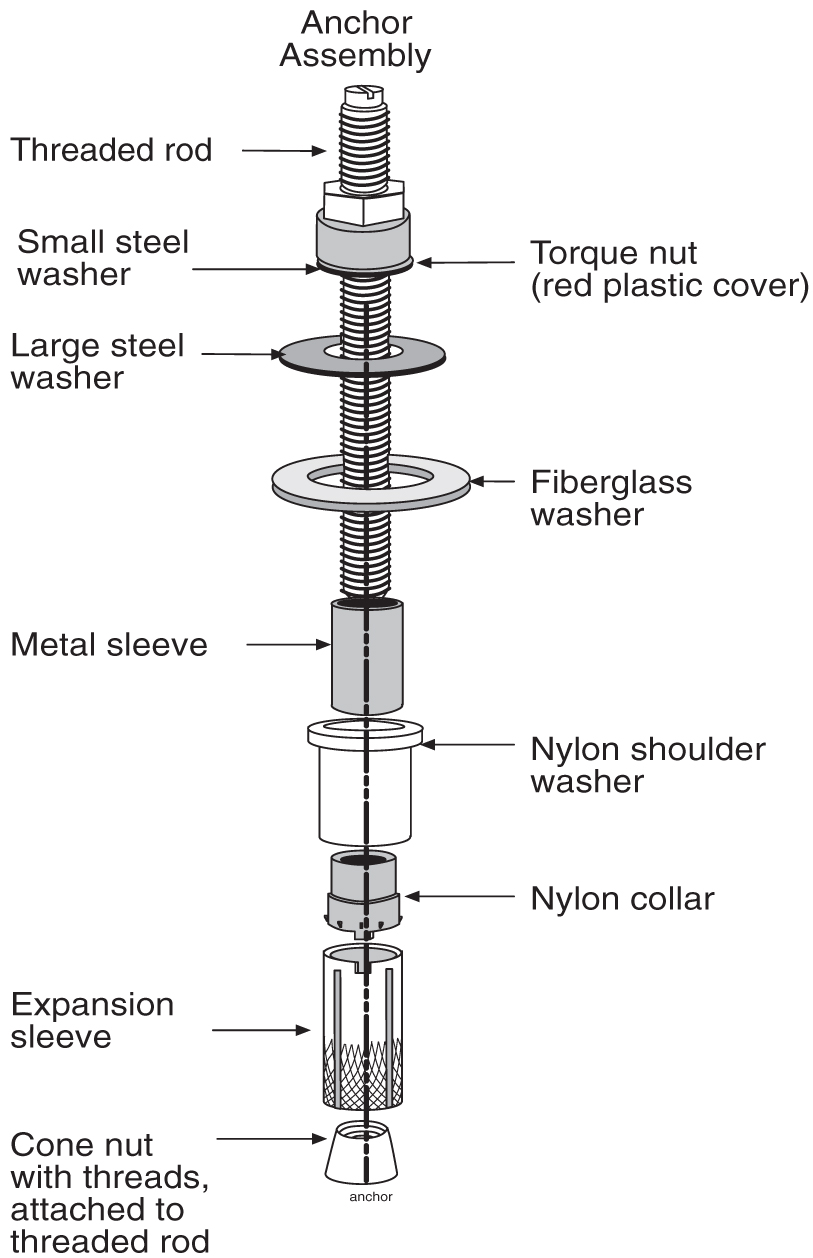
- Check the hole to make sure the fully assembled anchors can be set into the concrete three inches. The metal sleeve shown in Figure 4-13 must be below the floor.
Figure 4-13 Anchor Assembly
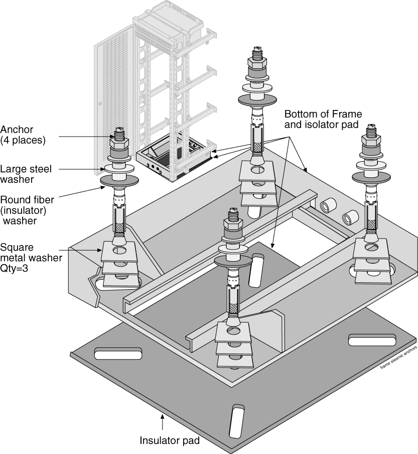
- Insert each anchor into an anchor hole through the three square washers, frame base, and isolation sheet (refer to Figure 4-14).
Figure 4-14 Anchor Installation of Heavy Duty Frame
4.3 Anchoring to Overhead Rack of Heavy Duty Frame
Frames with shelves that may be extended by pulling the shelf into the aisle must be attached to overhead ladder racks to prevent toppling.
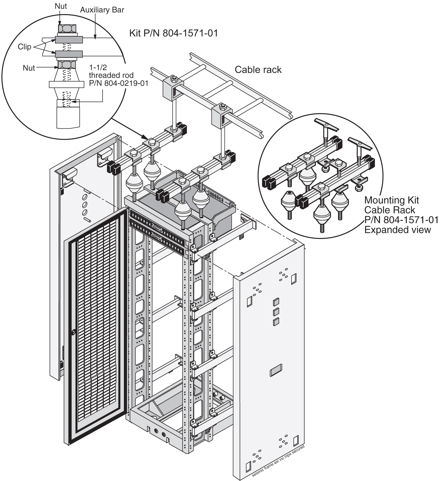
- Secure the top of the frame to the overhead cable ladder rack using a threaded rod with hardware as shown in Figure 4-15.
Figure 4-15 Heavy Duty Frame Installation With Cable Rack
4.4 Removing Frame Panels
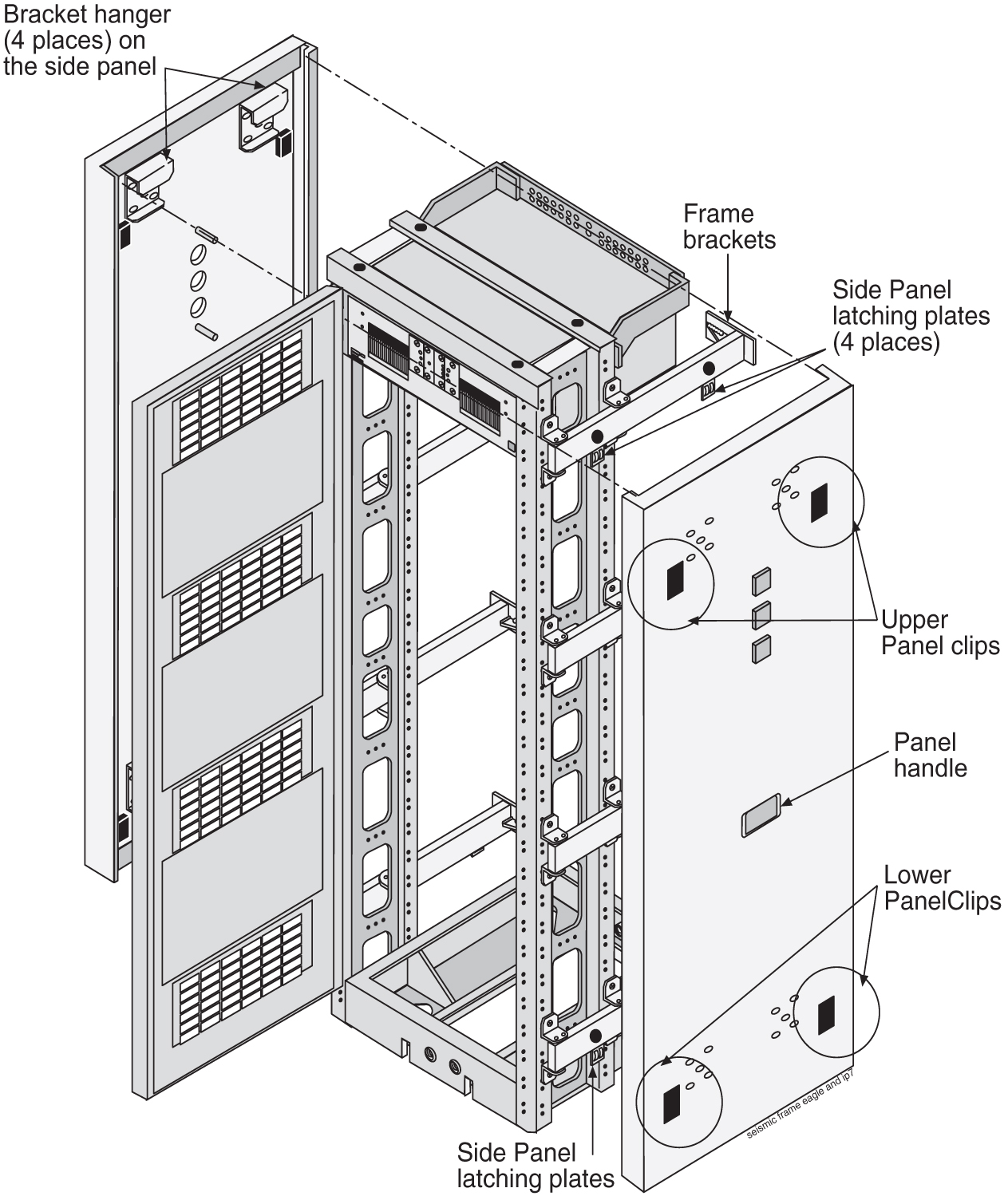
- Grasp the handle in the middle panel and lift the panel off of the frame bracket shown in Figure 4-16 .
Figure 4-16 Heavy Duty Frame Panels
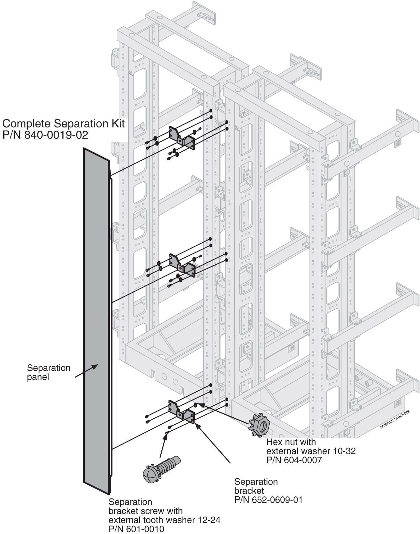
4.5 Installing Unit Separation Brackets
- Use 12 screws to attach three unit separation brackets with studs as shown in Figure 4-17.
Figure 4-17 Unit Separation Bracket Installation
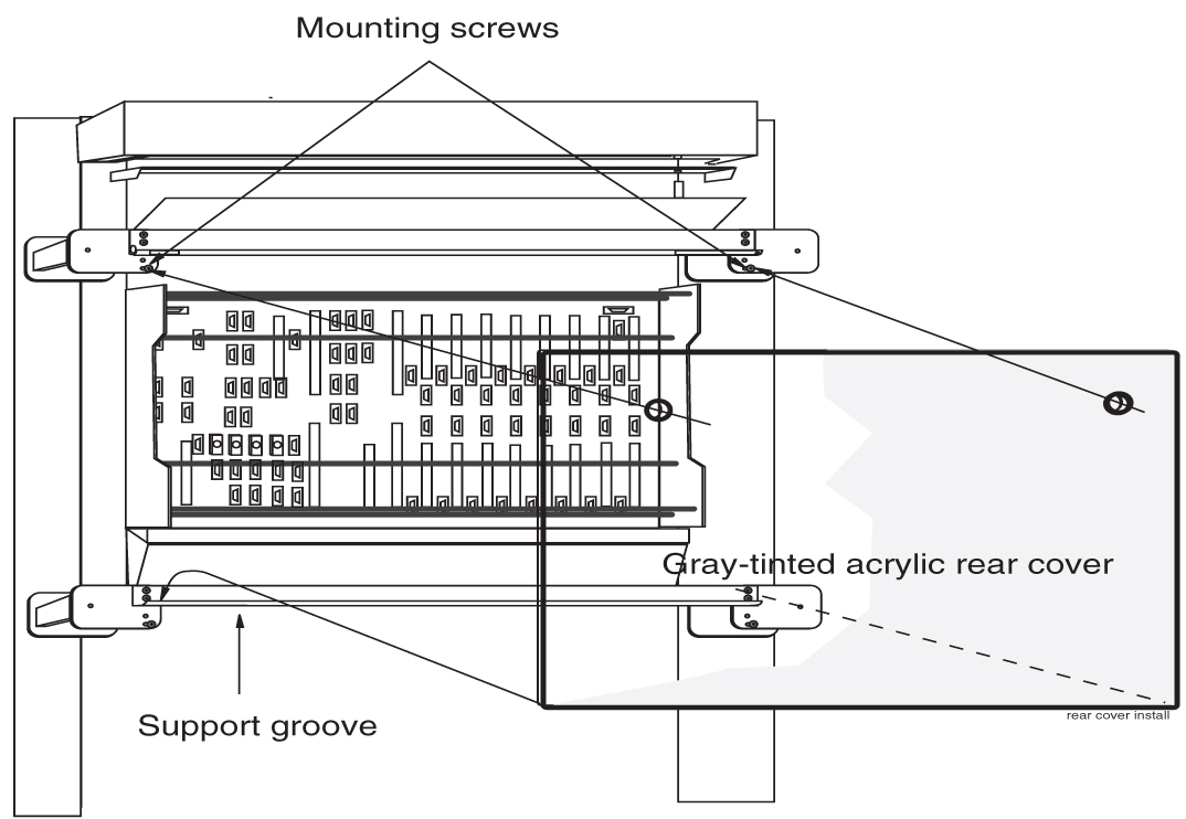
4.6 Rear Covers
Gray tinted plastic rear covers with round holes are provided, three per frame, to physically protect the system backplanes and cables, see Figure 4-18.
- Secure rear cover in place with two screws.For more information on Frames and Shelves refer to the Hardware Description Manual included in your current documentation suite.
Figure 4-18 Rear Cover Installation
4.7 Shelves
Figure 4-19 shows the frame door ground.
Figure 4-19 EAGLE Frame with Door Ground
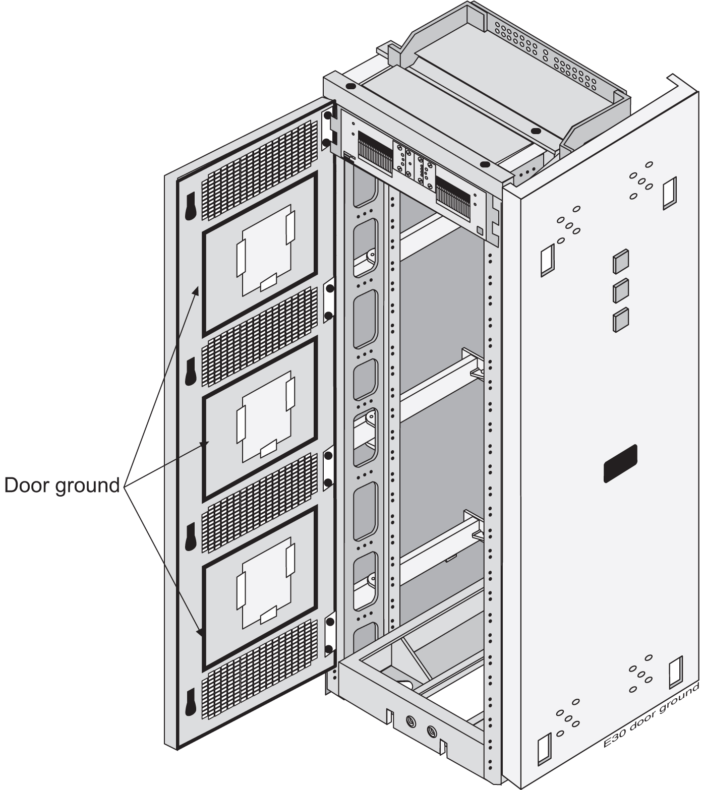
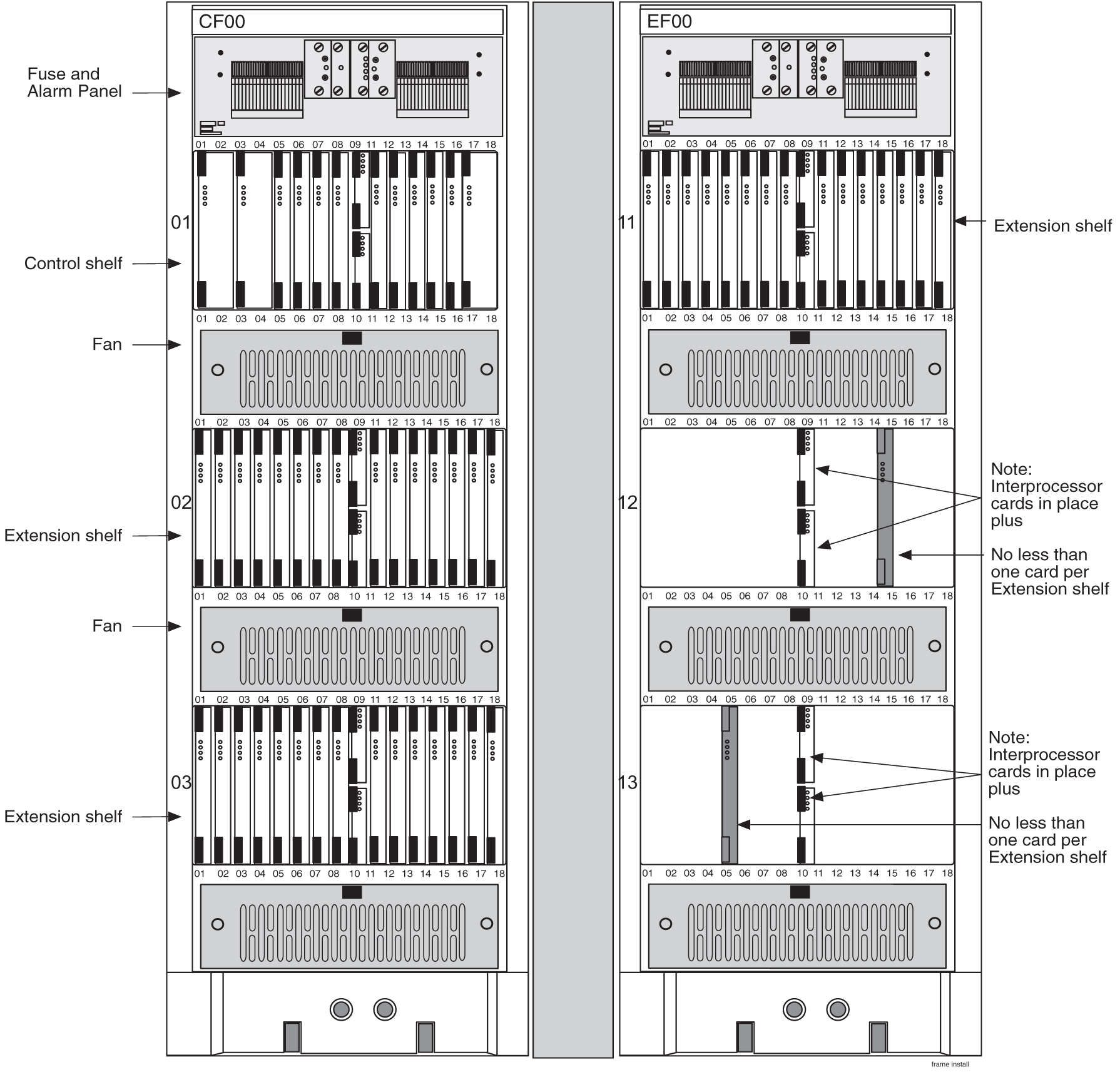
Figure 4-20 shows a frame with possible shelf population.
Figure 4-20 EAGLE Frame with Shelves
4.8 Labeling
4.8.1 End Aisle Labeling
This section details the application of the frame lineup end aisle labels. All of the frame lineups are labeled the same way on end panels.
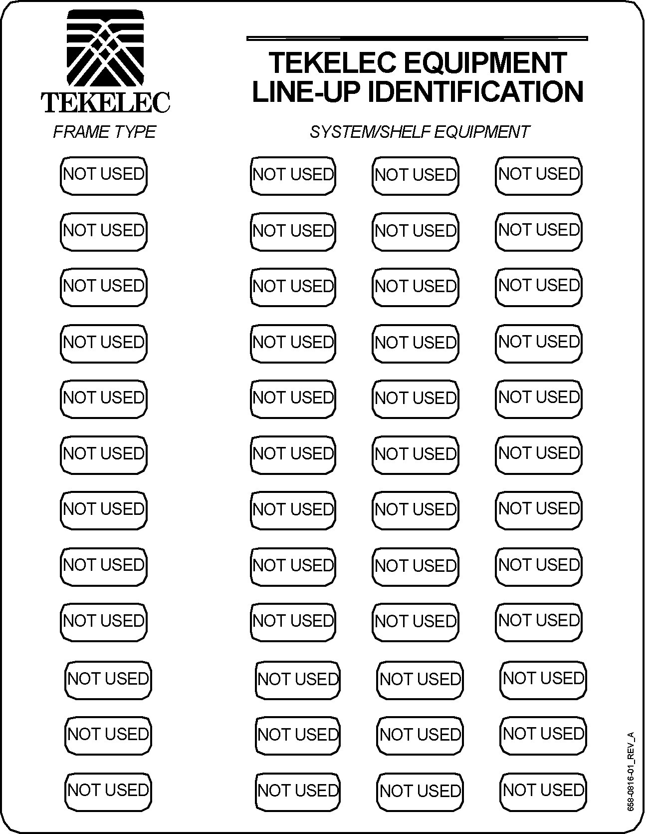
The frame lineup identification placard (P/N 658-0816-01) is applied to the side panel of the end aisle frame. This placard, when populated, shows each frame type and shelf used in the lineup. Frame Type labels and System/Shelf Equipment labels from the equipment identification sheets (P/N 658-1093-01) are used to populate the placard.
The placard lists the frame lineup with the top line of the placard corresponding to the frame nearest the end aisle to which the placard is attached.
- From the clear pocket, remove the frame lineup identification placard (P/N 658-0816-01).
Figure 4-21 Frame Lineup Identification Placard (P/N 658-0816-01)
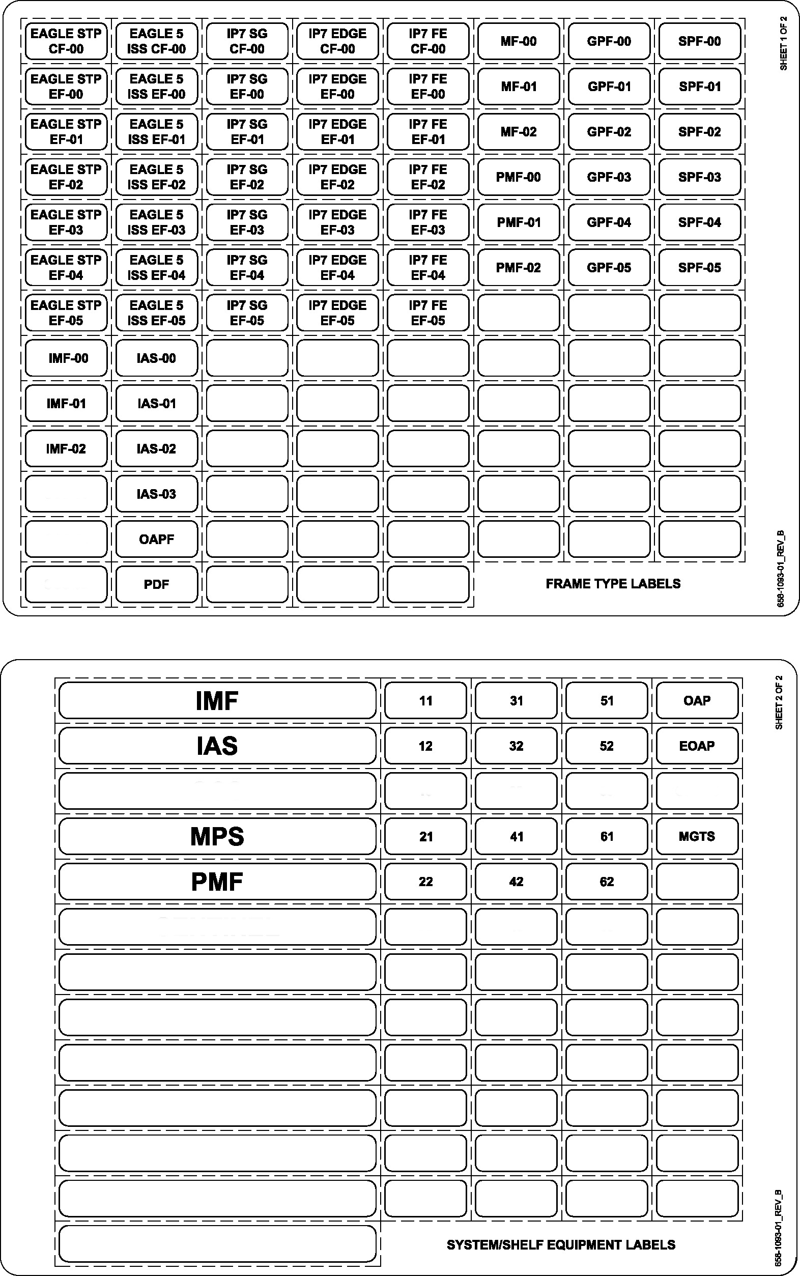
- From the equipment identification sheets (P/N 658-1093-01), remove the appropriate Frame Type label and System/Shelf Equipment labels and place them on the frame lineup identification placard. See Table 4-1 .
Note:
The top line of the placard corresponds to the frame nearest the end aisle to which the placard is attached.Table 4-1 Frame Type and Labels
Application Frame Type System/Shelf Equipment EAGLE- Control FrameCF- 00 Single Control Shelf
EAGLE
CF-00
11
EAGLE- Control Frame CF-00 Single Control Shelf + 1200 extension shelf
11
12
EAGLE- Control Frame CF-00 Single Control Shelf + 1200 and 1300 extension shelf
11
12
13
EAGLE- Extension Frame EF-00 with 2100 extension shelf EAGLE
EF-00
21
EAGLE- Extension Frame EF-00 with 2100 and 2200 extension shelves
21
22
EAGLE- Extension Frame EF-00 with 2100, 2200 and 2300 extension shelves
21
22
23
EAGLE- Extension Frame EF-01 with 3100 extension shelf
EAGLE
EF-01
31
EAGLE- Extension Frame EF-01 with 3100 and 3200 extension shelves
31
32
EAGLE- Extension Frame EF-01 with 3100, 3200 and 3300 extension shelves
31
32
33
EAGLE- Extension Frame EF-02 with 4100 extension shelf
EAGLE
EF-02
41
EAGLE- Extension Frame EF-02 with 4100, and 4200 extension shelves
41
42
EAGLE- Extension Frame EF-02 with 4100, 4200 and 4300 extension shelves
41
42
43
EAGLE- Extension Frame EF-03 with 5100 extension shelf
EAGLE
EF-03
51
EAGLE- Extension Frame EF-03 with 5100 and 5200 extension shelves
51
52
EAGLE- Extension Frame EF-03 with 5100, 5200 and 5300 extension shelves
51
52
53
EAGLE- Extension Frame EF-04 with 6100 extension shelf
EAGLE
EF-04
61
Misc Frame
GPF-00
MPS
GPF-00 trhu GPF-05
MPS
LSMS
GPF-00 trhu GPF-05
MPS
Sentinel
SPF-00 thru SPF-05
Sentinel
SCS
SCS-00 thru SCS-02
SCS
IMF
IMF-00 thru IMF-02
IMF
PMF
PMF-00 thru PMF-01
PMF
Figure 4-22 Frame Type and System/Shelf Equipment Label Sheets (P/N 658-1093-01)
4.8.2 Frame Labeling
This section details the application of frame and shelf labels. Additional labels on the newer heavy duty frame shown in Figure 4-23 come pre-installed.
Figure 4-23 Heavy-Duty Frame Label Location

Note:
The heavy-duty frame comes from manufacturing with the assembly information label in place.All of the frames shown in Table 4-2 are labeled the same way on end panels and separation panels, see Figure 4-24 and Figure 4-25.
Apply frame labels to the front of each frame as shown in Figure 4-24.
Table 4-2 Frame Labels and Part Numbers
| Frame | Label | Label Part Number |
|---|---|---|
|
CF-00 |
658-0486-01 |
|
|
EF-00 |
658-0486-02 |
|
|
EF-01 |
658-0486-03 |
|
|
EF-02 |
658-0486-04 |
|
|
EF-03 |
658-0486-05 |
|
|
EF-04 |
658-0486-06 |
|
|
MF-00 |
658-0374-01 |
|
|
Miscellaneous frame 01 |
MF-01 |
658-0374-02 |
|
GPF |
658-0374-01 |
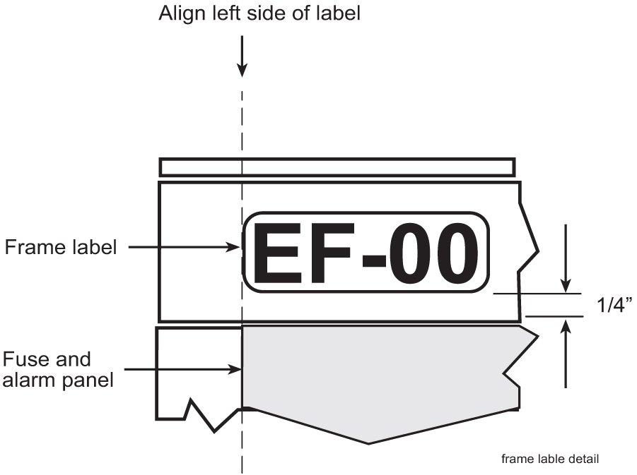
- Firmly press the label into place as shown in Figure 4-24 and Figure 4-25..
Figure 4-24 Frame and Shelf Label Locations
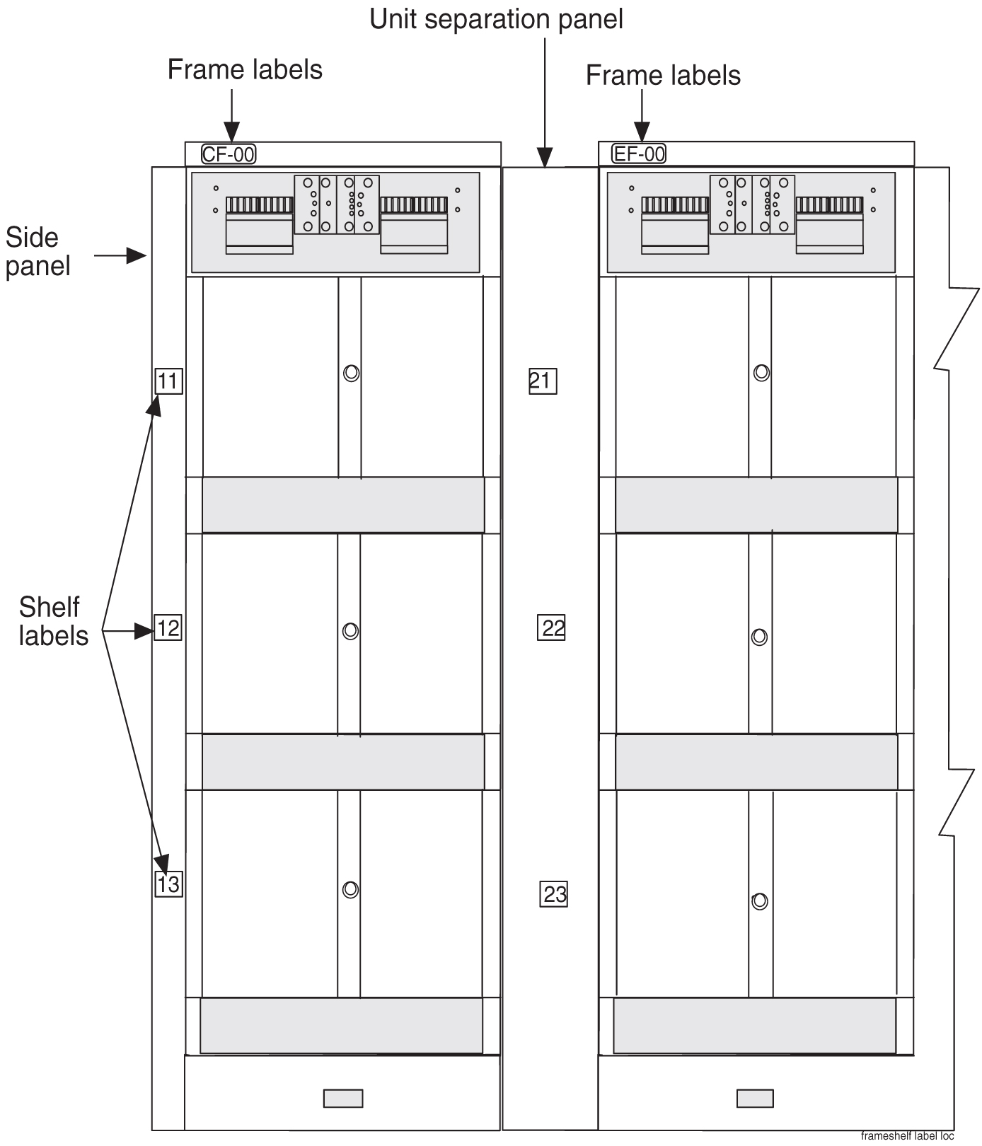
Figure 4-25 Frame Label Location - Detail
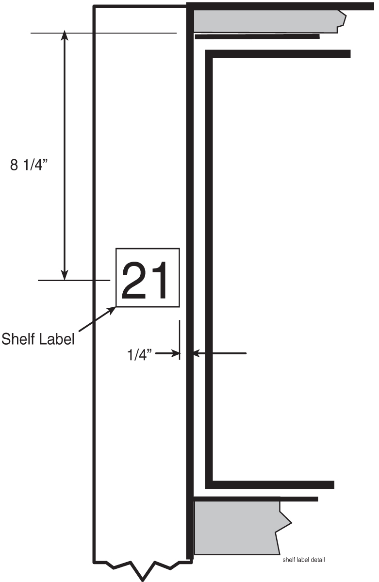
4.8.3 Shelf Labeling
Apply shelf labels to the frames of the system as shown in Frame Labeling. Refer to Figure 4-26 for exact placement. Refer to Table 4-3 for the proper label for each shelf.
Note:
The procedure for the placement of labels is the same on most of the frames. Typically, the system is pre-labeled.Table 4-3 Shelf Labels and Part Numbers
| Frame | Shelf | Label | Label Part Number |
|---|---|---|---|
|
Control Frame CF-00 The Control Frame is always the FIRST frame |
1 |
11= Frame 1 and Shelf 1 |
658-0490-01 |
|
2 |
12= Frame 1 and Shelf 2 |
658-0490-02 |
|
|
3 |
13= Frame 1 and Shelf 3 |
658-0490-03 |
|
|
Extension Frame EF-00 Extension Frame 00 is the first extension frame but the second frame in the line-up |
1 |
21= Frame 2 and Shelf 1 |
658-0490-04 |
|
2 |
22= Frame 2 and Shelf 2 |
658-0490-05 |
|
|
3 |
23= Frame 2 and Shelf 3 |
658-0490-06 |
|
|
Extension Frame EF-01 Extension Frame 01 is the second extension frame but the third frame in the line-up (numbering continues in additional frames) |
1 |
31= Frame 3 and Shelf 1 |
658-0490-07 |
|
2 |
32= Frame 3 and Shelf 2 |
658-0490-08 |
|
|
3 |
33= Frame 3 and Shelf 3 |
658-0490-09 |
|
|
Extension Frame EF-02 |
1 |
41 |
658-0490-10 |
|
2 |
42 |
658-0490-11 |
|
|
3 |
43 |
658-0490-12 |
|
|
Extension Frame EF-03 |
1 |
51 |
658-0490-13 |
|
2 |
52 |
658-0490-14 |
|
|
3 |
53 |
658-0490-15 |
|
|
Extension Frame EF-04 |
1 |
61 |
658-0490-16 |
|
As needed |
As needed |
- Firmly press the label into place as shown in Frame Labeling and Figure 4-26.
Figure 4-26 Shelf Label Location - Detail