5 Fuses and Alarm Panel
5.1 Fuse and Alarm Panels
The Fuse and Alarm Panel (FAP) provides protected distribution of –48VDC power to the shelves in the frame. The site voltage input to each frame should be between -40VDC and -57.5VDC. Allowing for the full population of a frame and for the failure of one primary supply, new installations of Control and Extension frames require two 60A feeds. See the "Hardware Power Calculator Tool" section in Hardware for more information.
The FAP is installed at the top of the frame and uses two cables to bring A and B power to the frame. The FAP contains two separate circuits, A and B. Current flows from the input terminals to the fuse bus. Protection is provided by fuses placed in fuse holders on the front panel. When a fuse is installed in a fuse holder, the circuit is completed to the output connector.
warning:
Existing frames that are fused at 40 amps may be upgraded to support 60 amps with a FAP upgrade kit. Frames that contain HC-MIMs must be upgraded to support 60 amps. Customers do not perform a FAP upgrade; these upgrades are performed by Oracle Communications personnel.warning:
The FAP P/N 870-1606-02 Revs A-B can be upgraded to FAP P/N 870-1606-02 Rev C with FAP upgrade kit P/N 840-0139-01. The FAP P/N 870-2320-01 Revs A-I can be upgraded to FAP P/N 870-2320-01 Rev J with FAP upgrade kit P/N 870-0139-02.Caution:
All personnel associated with the installation of this system must adhere to all safety precautions and protection equipment required to avoid the possibility of injury to personnel, service degradation, and/or service interruption.Caution:
This is a redundant system to allow service during normal maintenance. When repairs require a total power disconnect, both input supply sources must be disconnected. This will cause service interruption and take down the system.5.1.1 Fuses
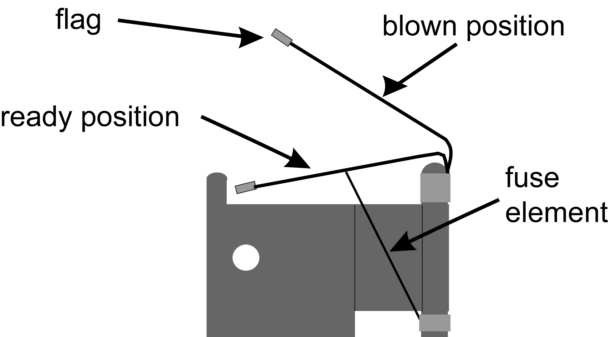
The fuse and alarm panel uses GMT-type fuses of different amperage ratings for individual circuit protection. If a frame circuit fuse is blown the alarm is indicated by an LED on the front panel and a small colored flag on the fuse shows the fuse that has failed (refer to Figure 5-1. Refer to Maintenance for procedures on replacing fuses and the FAP assembly.
Caution:
Always use a fuse of the same type and amperage rating when replacing a failed fuse.Figure 5-1 Fuse (GMT Brand Shown)
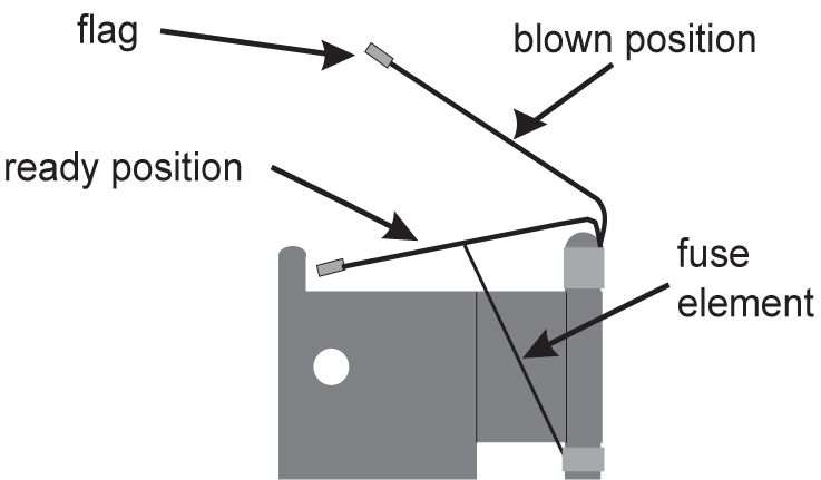
Table 5-1 Fuse Color Codes of Alarm Flags
| Fuse Amp | Fuse Flag Color | Fuse Amp | Fuse Flag Color |
|---|---|---|---|
|
0.18A |
Orange-Red |
2A |
Orange |
|
0.2A |
Black-Red |
2.5A |
White-Orange |
|
0.25A |
Violet |
3A |
Blue |
|
0.33A |
Yellow-Green |
3.5A |
White-Blue |
|
0.375A |
White-Green |
4A |
White -Brown |
|
0.5A |
Red |
5A |
Green |
|
0.65A |
Black |
7.5A |
Black-White |
|
0.75A |
Brown |
10A |
Red-White |
|
1A |
Gray |
12A |
Yellow-Green |
|
1.33A |
White |
15A |
Red-Blue |
|
1.5A |
White-Yellow |
5.1.2 Fuse and Alarm Panel (P/N 870-2804-01)
The FAP (P/N 870-2804-01) is a low-profile (1U) unit that can be installed in the Control Frame (CF) and the Extension Frame (EF).
The Power Alarm LED indicates the input power state to the FAP. The LED is green when input power is applied to that bus of the FAP and is red when there is no input power to that bus of the FAP. An unlit Power Alarm LED indicates a failed LED or no input power to either bus of the FAP.
Alarm LEDs to indicate Critical, Major, and Minor alarms are located to the left of the diode board. The LEDs indicate alarms generated by the system that are applicable to that frame which the FAP is installed.
The FAP contains a Diode board and a Shorting board. These boards are located at the front center of the FAP. The FAP also contains two fuse blocks, one to the left (A-side) and one to the right (B-side) of diode and shorting boards, consisting of 20 fuse positions each. The Fuse Alarm LED indicates the failure of a fuse.
The diode board in the FAP contains power diodes and circuitry which allow one bus to pick up the entire load when there is a loss of input power on the other bus.
The Shorting board allows the removal of the diode board without taking down the system. This permits periodic maintenance of the diodes without having to power down or remove the unit from the shelf. For maintenance operation, the Shorting board has to be removed, flipped over, and reinstalled. In the bypass position, both A and B power is connected to the fuse blocks so the diode board can be safely removed. The Shorting board has an LED which is off when the board is in normal operational mode and is green when in the bypass mode of operation. With the Shorting board in the bypass mode, the OR’ing function is not available. Refer to Maintenance for additional information to place the FAP into Maintenance Mode of operation.
Figure 5-2 and Table 5-2 describes the front panel configuration of the fuse and alarm panel (P/N 870-2804-01).
Figure 5-2 Fuse and Alarm Panel - Front View (P/N 870-2804-xx)
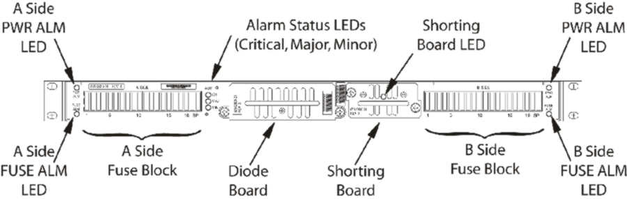
Table 5-2 Fuse and Alarm Panel Front Items (P/N 870-2804-xx)
| Fuse Panel Item | Description |
|---|---|
|
Fuse Positions |
Two groups of 20 GMT fuses |
|
Shorting Board LED |
LED indicator for shorting board. |
|
FuseAlarm |
LED indicator for fuse fail alarm |
|
PowerAlarm |
LED indicator for input power |
|
CriticalAlarm |
LED indicator for critical alarm |
|
MajorAlarm |
LED indicator for major alarm |
|
MinorAlarm |
LED indicator for minor alarm |
Table 5-3 presents possible alarm LED states and corresponding fuse conditions.
Table 5-3 Fuse State and LED condition (P/N 870-2804-01).
| Fuse State A side | Fuse State B side | Fuse LEDs A side | Fuse LEDs B side |
|---|---|---|---|
|
No fuses blown |
No fuses blown |
Green |
Green |
|
No fuses blown |
At least 1 fuse blown |
Green |
Red |
|
At least 1 fuse blown |
No fuses blown |
Red |
Green |
|
At least 1 fuse blown |
At least 1 fuse blown |
Red |
Red |
|
Shorting board enabled (in bypass mode), Shorting board LED is green. |
Red |
Red |
|
|
Shorting board in normal operational mode, Shorting board LED is off. No fuses blown. |
Green |
Green |
Figure 5-3 and Table 5-4 describes the rear panel configuration. Refer to Installation for cabling connection information.
Figure 5-3 Fuse and Alarm Panel Rear (P/N870-2804-01).
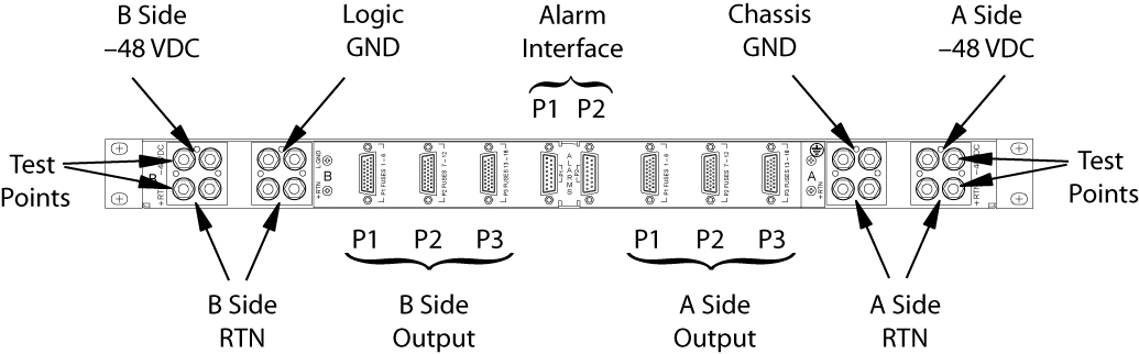
Table 5-4 Fuse and Alarm Panel Rear Items (P/N870-2804-01).
| Fuse Panel Item | Description |
|---|---|
|
Input Terminal Block A |
Input and Return for power source A and FAP Chassis Ground |
|
Input Terminal Block B |
Input and Return for power source B and FAP Logic Ground |
|
–48VDC Outputs A |
26-pin “D” connectors for A-side outputs:
|
|
–48VDC Outputs B |
26-pin “D” connectors for B-side outputs:
|
|
Alarm Interface |
15-pin “D” connectors:
|
Table 5-5 presents the power requirements and physical dimensions for the FAP.
Table 5-5 Fuse and Alarm Panel Specifications (P/N 870-2804-01).
| Dimensions | |
|---|---|
|
Height Width Depth |
1.75 inches (4.4 cm) 21.5 inches (53.8 cm) 10 inches (25 cm) |
5.1.2.1 Shorting Board
The Shorting board allows the removal of the diode board without taking down the system. This permits periodic maintenance of the diodes without having to power down or remove the unit from the shelf. The Shorting board has an LED which is off when the board is in normal operational mode and is green when in the bypass mode of operation. With the Shorting Board in the maintenance mode, the Diode Board can be removed for maintenance while still allowing the FAP to operate. No OR'ed power is available in this mode. After installing the Diode Board, the Shorting Board must be reset to normal mode.
5.1.2.1.1 Maintenance Mode
This section describes how to place the Shorting Board into maintenance (bypass) mode. Maintenance mode allows the removal of the Diode Board without taking down the system.
Procedure — Shorting Board Maintenance Mode
-
Check to verify the Shorting Board LED is not on, indicating the FAP is in normal mode.2.
-
Locate two screws securing the Shorting Board in its slot (see Figure 5-4). Note the orientation of the Shorting Board LED. Turn the screws at each corner of the board to the left until they disengage.
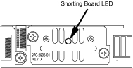
Figure 5-4 Shorting Board Faceplate, Normal Mode
-
Pull the board straight out of the FAP until the board is clear of the frame.
-
Turn the Shorting Board over and reinsert the board into its slot. Note the orientation of the Shorting Board LED (see Figure 5-5).
Figure 5-5 Shorting Board Faceplate, Maintenance Mode
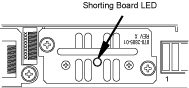
The Shorting Board LED turns green and the fuse alarm LEDs turn red.
-
Ensure the board is seated properly and tighten the two screws to secure the board.
-
The Shorting Board is now in the maintenance (bypass) mode of operation.
5.1.2.1.2 Normal Mode
Use this procedure to place the Shorting board into normal mode. This mode of operation allows one bus to pick up the entire load when there is a loss of input power on the other bus.
Procedure — Shorting Board Normal Mode
-
Check to verify the Shorting Board LED is green, indicating the FAP is in maintenance mode.
-
Locate two screws securing the Shorting Board in its slot. Note the orientation of the Shorting Board LED (Figure 5-6). Turn the screws at each corner of the board to the left until they disengage.
Figure 5-6 Shorting Board Faceplate, Maintenance Mode
-
Pull the board straight out of the FAP until the board is clear of the frame.
-
Turn the Shorting Board over and reinsert the board into its slot. Note the orientation of the Shorting Board LED (see Figure 5-7).
Figure 5-7 Shorting Board Faceplate, Normal Mode
Note:
The Shorting Board LED is off and the fuse alarm LEDs turn green. -
Ensure the board is seated properly and tighten the two screws to secure the board.
-
The Shorting Board is now in the normal mode of operation.
5.1.3 Fuse and Alarm Panel (P/N 870-1606-xx/870-2320-xx)
The FAP P/N 870-1606-xx can be installed in standard frames. The FAP P/N 870-2320-xx can be installed in heavy duty frames.
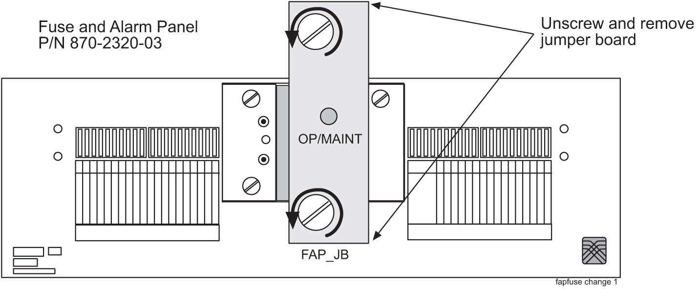
The FAP contains an alarm board, two diode boards, and a jumper board. These boards are located at the front center of the FAP. The fuse holders are to the left and right of these boards as shown in Figure 5-8.
The alarm board contains a FUSELED to indicate a failed fuse (for either bus A or B) and LEDs to indicate Critical, Major, and Minor alarms generated by the system that are applicable to that frame which the FAP is installed.
There are two diode boards in the FAP, one for bus A and one for bus B. Each diode board contains power diodes and circuitry which allow one bus to pick up the entire load when there is a loss of input power on the other bus. An LED indicates the input power state to the FAP. The LED is green when input power is applied to that bus of the FAP and is red when there is no input power to that bus of the FAP.
The Maintenance (Jumper) board allows the removal of one or both diode boards without taking down the system. The Jumper board has two connectors and a connector plug. During normal operation, the connector plug is seated on the first connector. For maintenance operation, the jumper board has to be removed and the connector plug moved to the second connector. In the maintenance position, the connector plug connects both A and B power feeds to the fuse panels so one or both diode boards can be safely removed. The OP/MAINTLED is green when the Jumper board is in normal operational mode and is red when in the maintenance mode of operation. Refer to Maintenance.Figure 5-8 and Table 5-6 describes the front panel configuration of the fuse and alarm panel (P/N 870-1606-xx/870-2320-xx).
Figure 5-8 Fuse and Alarm Panel (P/N 870-1606-xx/870-2320-xx) Front
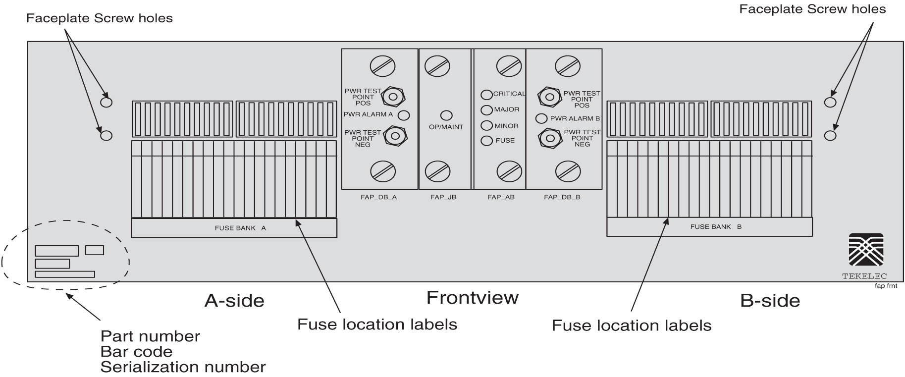
Table 5-6 Fuse and Alarm Panel Front Items
|
Fuse Panel Item |
Description |
|
Fuse Positions |
Two groups of 20 GMT fuses |
|
PWR ALARM |
LED indicator for A or B diode board input power
|
|
OP/MAINT |
LED indicator for mode of operation
|
|
FUSE |
LED indicator for fuse fail alarm
|
|
CRITICAL |
LED indicator for frame critical alarm |
|
MAJOR |
LED indicator for frame major alarm |
|
MINOR |
LED indicator for frame minor alarm |
Figure 5-9 describes the rear panel configuration of fuse and alarm panel (P/N 870-1606-xx). Refer to Installation for cabling connection information.
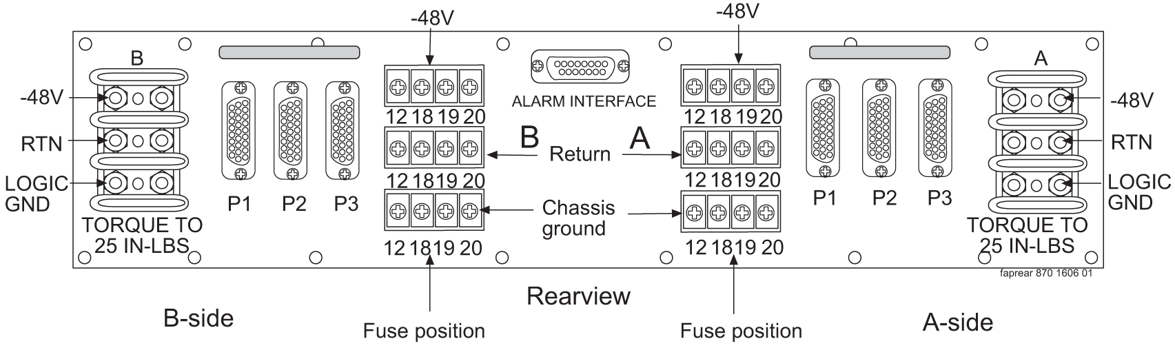
Figure 5-9 Fuse and Alarm Panel (P/N 870-1606-xx/870-2320-xx) Rear
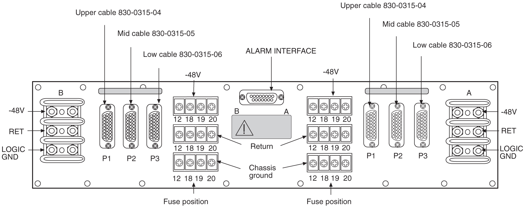
Table 5-7 Fuse and Alarm Panel (P/N 870-1606-xx/870-2320-xx) Rear
| Fuse Panel Item | Description |
|---|---|
|
Input Terminal Block A |
Logic Ground, Return, and Input for power source A |
|
Input Terminal Block B |
Logic Ground, Return, and Input for power source B |
|
Output Terminal Block A |
–48VDC, Chassis Ground, and RTN for Fuse location 12, 18, 19, and 20 for side A. These are miscellaneous extra capacity fuses refer to Provision Rules for FAP Fuse Locations . |
|
Output Terminal Block B |
–48VDC, Chassis Ground, and RTN for Fuse location 12, 18, 19, and 20 for side B. These are miscellaneous extra capacity fuses refer to Provision Rules for FAP Fuse Locations |
|
–48VDC, Chassis Ground, and RTN Outputs A |
26-pin “D” connectors, P1, P2, and P3 for A-side outputs. |
|
–48VDC, Chassis Ground, and RTN Outputs B |
26-pin “D” connectors, P1, P2, and P3 for B-side outputs. |
Table 5-8 Fuse and Alarm Panel (P/N 870-1606-xx/870-2320-xx) Specifications
| Dimensions | |
|---|---|
|
Height Width Depth |
3 inches (7.6 cm) 17 inches (43.2 cm) 10.25 inches (26 cm) |
5.1.3.1 Jumper Board
The Jumper board has two connectors and a connector plug. During normal operation, the connector plug is seated on the first connector. For maintenance operation, the jumper board has to be removed and the connector plug moved to the second connector. In the maintenance position, the connector plug connects both A and B power feeds to the fuse panels so one or both diode boards can be safely removed. The OP/MAINT LED is green when the Jumper board is in normal operational mode and is red when in the maintenance mode of operation.
5.1.3.1.1 Maintenance Mode
Use this procedure to place the jumper board into maintenance mode. Maintenance mode allows the removal of one or both diode boards without taking down the system.
Procedure — Maintenance Mode
-
Locate the jumper board on the Fuse and Alarm Panel (FAP). See Figure 5-10.
Figure 5-10 Jumper Board FAP
-
Remove the Jumper Board (FAP_JB) by turning the top and bottom screws to the left until they disengage.
-
Pull the board straight out of the FAP until the board is clear of the frame.
-
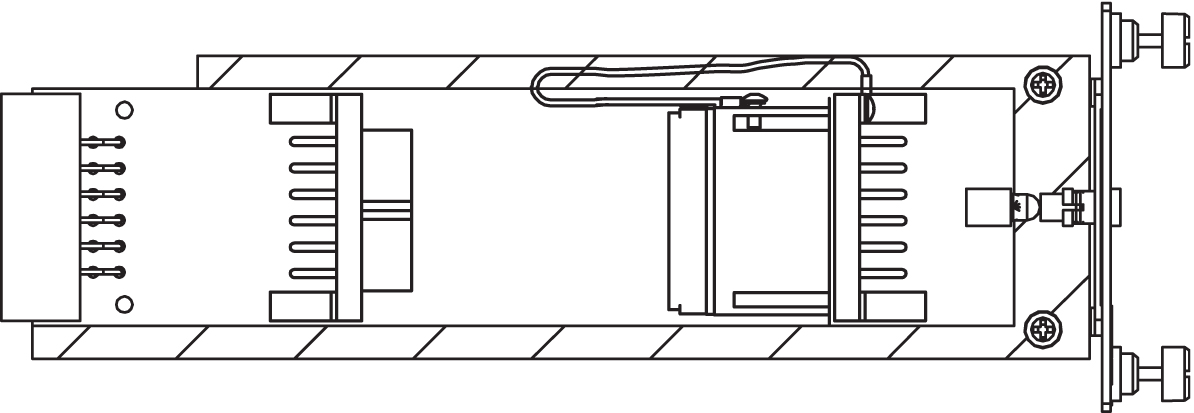
On the jumper circuit board, unclip the 12-pin connector jumper from P71 and re-attach it to P72. Insert it until the plastic retaining clips “snap”. See Figure 5-11. Note that the jumper has a retaining strap so it will not get dropped or lost. This repositioning overrides the diodes, establishing a direct connection between the input and fuse panels.
Figure 5-11 Jumper Connector - Maintenance Mode.
-
Slide the jumper board back into the FAP and verify both of the following alarms display:
-
the OP/MAINT LED lights red on the FAP
-
an EAGLE fuse alarm displays on the terminal
You may now remove either or both diode circuit boards without affecting EAGLE service.
Note:
Using the jumper override negates the backpower protection usually provided by the diode board.The jumper board maintenance mode procedure is completed.
-
Procedure — Operational Mode
-
Unscrew the two thumbscrews securing the FAP jumper board and remove the board.
-
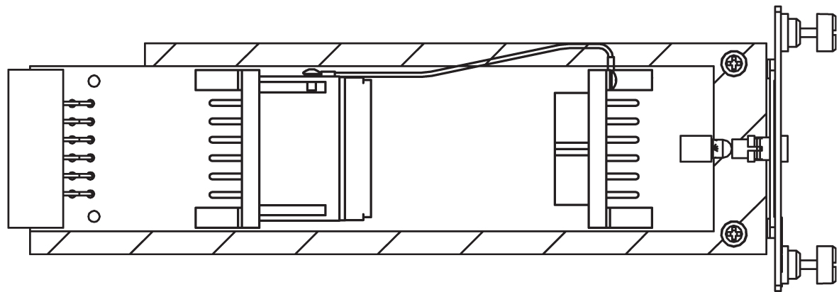
On the jumper circuit board, unclip the 12-pin connector jumper from P72 and re-attach it to P71. Insert it until the plastic retaining clips “snap”. See Figure 5-12. Note that the jumper has a retaining strap so it will not get dropped or lost. This repositioning establishes a connection between the diode boards with the input and fuse panels.
Figure 5-12 Jumper Connector - Operational Mode.
-
Slide the jumper board back into the FAP. Verify the OP/MAINT LED lights green. The fuse alarm LED returns to green.
The jumper board operational mode procedure is completed.
5.1.3.1.2 Operational Mode
Use this procedure to place the jumper board into operational mode. This mode of operation allows one bus to pick up the entire load when there is a loss of input power on the other bus.
Procedure — Operational Mode
-
Unscrew the two thumbscrews securing the FAP jumper board and remove the board.
-
On the jumper circuit board, unclip the 12-pin connector jumper from P72 and re-attach it to P71. Insert it until the plastic retaining clips “snap”. Note that the jumper has a retaining strap so it will not get dropped or lost. This repositioning establishes a connection between the diode boards with the input and fuse panels.
Figure 5-13 Jumper Connector - Operational Mode.
-
Slide the jumper board back into the FAP. Verify the OP/MAINT LED lights green. The fuse alarm LED returns to green.
The jumper board operational mode procedure is completed.
5.1.4 Provision Rules for FAP Fuse Locations
The following are provisioning rules for fuse placement apply to FAP P/N870-2804-xx:
-
Maximum fuse size 3 amp.
-
Fuse positions 19 and 20 not used.
-
Power feed must originate from the same power source.
-
Fuse and Alarm Panel Shorting board in bypass mode must be less than 40 amp per distributed output side.
These provisioning rules for fuse placement apply to FAPs P/N 870-1606-xx and P/N 870-2320-xx.
-
Maximum fuse size 3 amp for Fuse one through Fuse 18 when P1, P2, or P3 are used for power output
-
P2 cannot be used if the Terminal Strip (output) position 12 is used.
-
P3 cannot be used if the Terminal Strip (output) position 18 is used.
-
Fuse maximum of 15 amp for fuse positions 12, 18, 19, and 20, all other fuse positions are 3 amp.
Note:
For fuse locations 12, 18, 19, and 20, the fuse maximum is 10 amp when adjacent locations are used. -
Power feed must originate from the same power source.
-
Fuse and Alarm Panel, Jumper Board (P/N 870-1641-01) fuse size on boards 40 amp per side for P/N 870-1606-02 Rev A and B, and for P/N 870-2320-01 Rev A through I. Fuse size on boards 60 amp per side for P/N 870-1606-02 Rev C and 870-2320-01 Rev J.
-
Fuse and Alarm Panel, Jumper board in maintenance mode must be less than 40 amp per distributed output side.
5.2 Installing Power Cables
Each frame is divided into A and B power buses. If loss of power on one of the buses occurs, the other bus must be able to supply current for the entire frame. Therefore, each bus requires wiring sized to match the FAP selection, with a maximum voltage drop of 0.5 volts. All frames containing HCMIM cards require 60A. The site voltage input to each frame should be between -40VDC and -57.5VDC. To meet this specification:
-
Fuse and wire each bus to support 40A if you have a FAP 870-2320-03 Rev A through Rev I, 870-0243-08 Rev C, or 870-0243-09 Rev C.
Note:
Existing frames that are fused at 40A can be upgraded to support 60A with a FAP upgrade kit. 60A are required for frames that contain HC-MIMs. Upgrades will be performed by Oracle personnel. Contact My Oracle Support (MOS) for more information. -
Fuse and wire each bus to support 60A if you have a FAP 870-2320-04 Rev J, or 870-2804-01 Rev A.
-
For Input Power, RTN, and Logic GND use only the following for Fuse and Alarm Panel connectors:
-
FAP P/N 870-2804-001; Straight, two-hole lugs, 1/4-inch on 5/8-inch centers, long barrel with windows (504-0817-02)
-
All other FAPs; Straight, two-hole lugs, #10 hole on 5/8-inch centers, long barrel with windows (502-0085-R01)
-
All connections to the FAP are #6AWG (number 6 American Wire Gage). Table 5-9 shows the list of required wiring sizes based on the length of the cable run. H-tap to the main feed where larger gauge wire is required for long cable runs.
Use H-taps at the fuse and alarm panel and power board to reduce the wire size to #6 AWG.
Note:
Specific wire sizes may be determined by the site requirements.Table 5-9 Power Cable Conductor Sizes
| Breaker Size in Amperes | Cable Length | Conductor Size (AWG) |
|---|---|---|
|
40A |
up to 40 ft. (12.2 meters) |
#6 |
|
up to 70 ft. (21.3 meters) |
#4 |
|
|
up to 110 ft. (33.5 meters) |
#2 |
|
|
up to 170 ft. (51.8 meters) |
1/0 |
|
|
up to 200 ft. (61 meters) |
2/0 |
|
|
up to 220 ft. (67.1 meters) |
4/0 |
|
|
60A |
up to 40 ft. (12.2 meters) |
#2 |
|
up to 70 ft. (21.3 meters) |
1/0 |
|
|
up to 110 ft. (33.5 meters) |
2/0 |
|
|
up to 170 ft. (51.8 meters) |
4/0 |
|
|
up to 200 ft. (61 meters) |
350MCM |
|
|
up to 220 ft. (67.1 meters) |
350MCM |
Note:
Where the cable leaves the cable rack, the cable must be protected with fiber paper throughout the system.5.2.1 Recommended Tools
Oracle tools should be labeled “Property of ORACLE” with either a press-on Field Tool Identification label or Field Tool Identification wrap.
-
Safety glasses
-
Multimeter
-
Lacing cord
-
Cable cutters
-
Cable stripper
-
Crimping tool, embossing dies
-
Socket wrench set with 1/4-inch or 3/8-inch drive or open end wrenches
-
Heat-shrink gun (hot air blower)
-
Torque wrench
-
Fiber paper
Note:
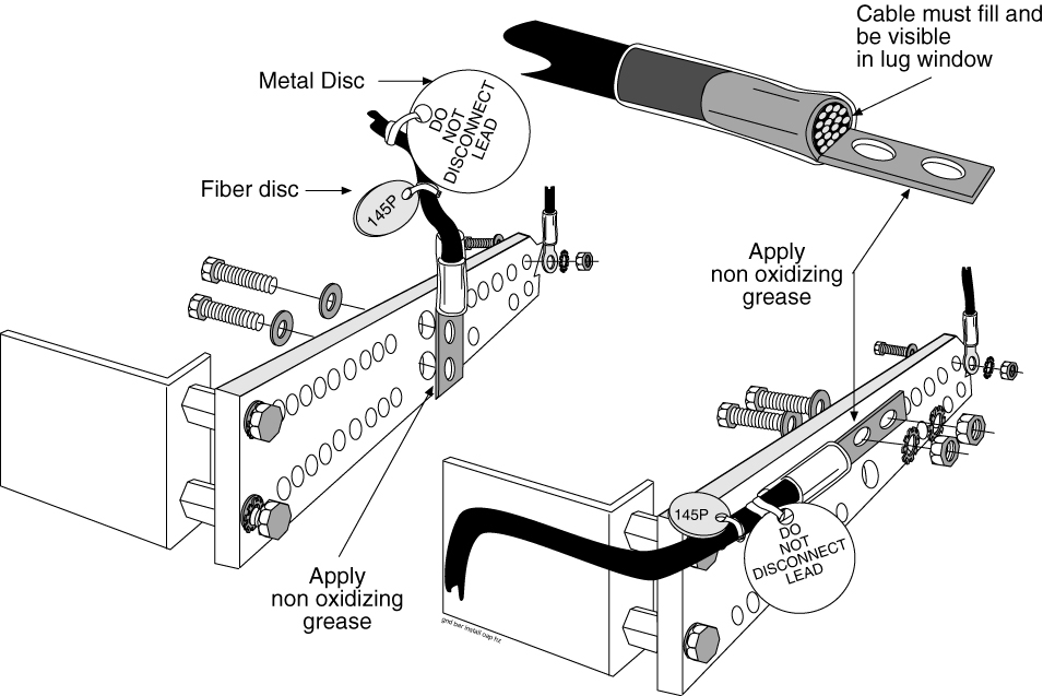
It is a requirement that when mating dissimilar metals non oxidizing grease is used between them as a corrosion inhibitor.- Apply non oxidizing grease to the stripped end of the cable, and install the lug. The stripped cable must fill lug completely to the end of the barrel of the lug and be visible in the end window of the lug.
Figure 5-14 Lug Installation

Note:
Input Power and RTN use straight, two hole lugs, 1/4-inch hole on 5/8-inch centers, long barrel with window (P/N 804-0817-02). - Fasten the lugs of the cables to the respective A-side and B-side -48VDC and RTN points on the FAP. Refer to Figure 5-15 and Figure 5-16.
Figure 5-15 1U Fuse and Alarm Panel Rear (P/N 870-2804-01)

Figure 5-16 3U Fuse and Alarm Panel Rear (P/N 870-2320-03))
 Tighten the lugs to:
- 1U FAP, torque to 50 inch-pounds
- 3U FAP, torque to 25 inch-pounds
5.3 Frame Ground and Logic Ground Cabling Procedures
This section covers these procedures:
- Ground Frame
- Connect Ground Cable to Control Frame
- Logic Ground Connections to the System Ground Bar
- Logic Ground Cables
Grounding Requirements
The system operates as a digital isolated ground plane system in a central office environment and requires a single connection to the central office ground window. The system’s ground cables must provide the sole grounding connection between the entire system and the central office grounding.
5.3.1 Recommended Tools
Oracle tools should be labeled “Property of ORACLE” with either a press-on Field Tool Identification label or Field Tool Identification wrap.
-
Safety glasses
-
Power knife
-
Cable cutters
-
Cable stripper
-
Flush cutters
-
Socket wrench set, 1/4-inch or 3/8-inch drive or open-end wrenches
-
Non oxidizing grease
Note:
It is a requirement that when mating dissimilar metals non oxidizing grease is used between them as a corrosion inhibitor. -
Lacing cord and nylon cable ties
-
Torque wrench
-
Fiber paper
5.3.3 Connect Ground Cable to Control Frame
Caution:
This equipment has a connection between the earthed conductor of the DC supply circuit and the earthing conductor.Note:
It is a requirement that when mating dissimilar metals non oxidizing grease is used between them as a corrosion inhibitor.- Install the ground cable lug using the 3/8-inch # 6
copper-plated hardware provided.
Use the attachment sequence shown in Figure 5-18..
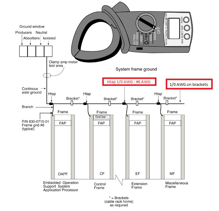
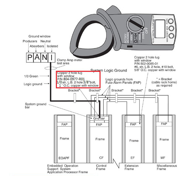
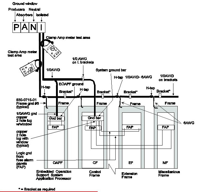
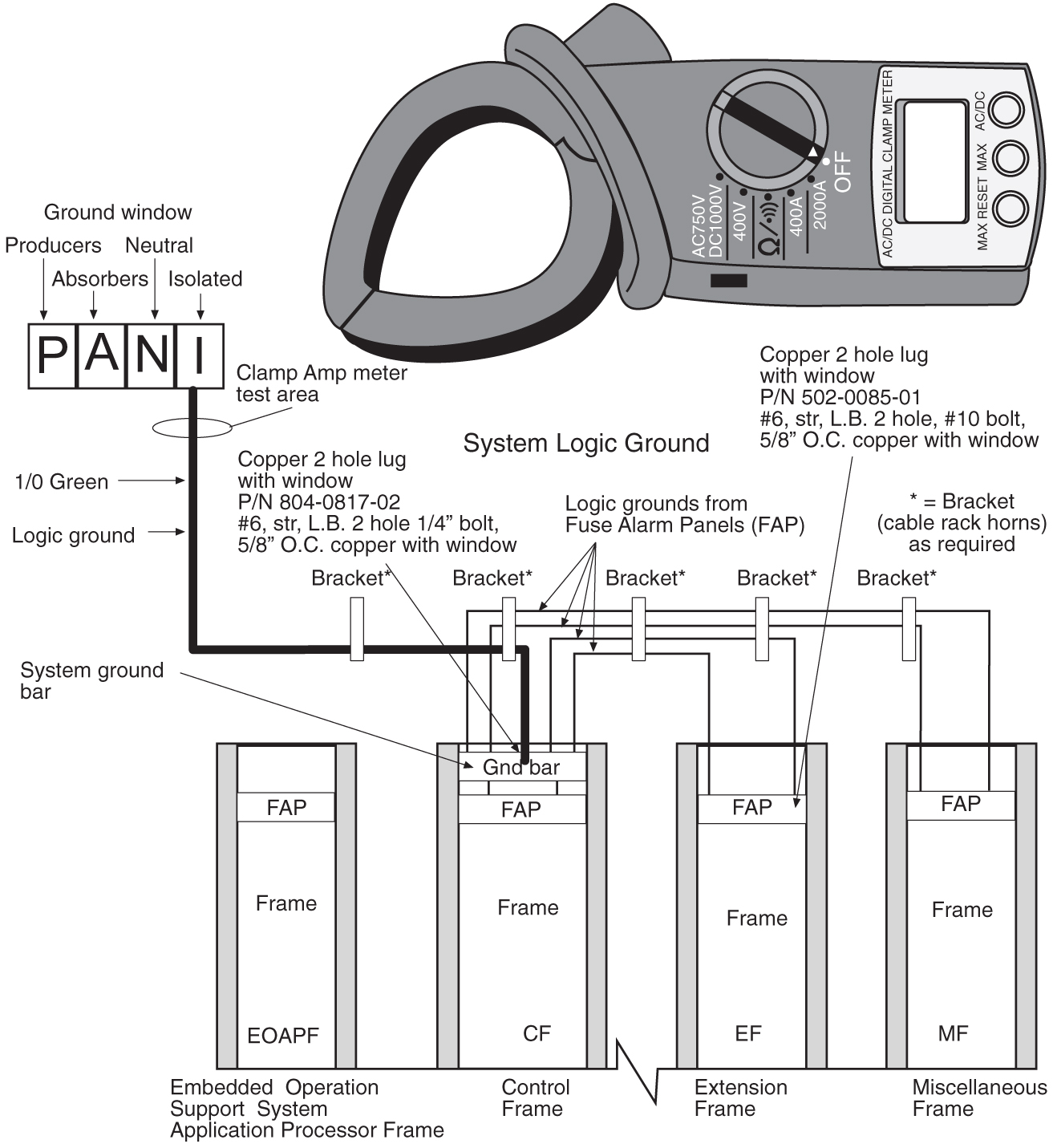
Figure 5-18 System Logic Grounding
- Use the lacing cord to secure a “DONOTDISCONNECTLEAD” tag at each end of the cable, just beyond the lug.
Note:
System Ground: 1/0 cable from the system ground bar to the “I” section of the ground window. If no ground window exists, the customer will designate the termination point.Note:
Frame Ground: A cable #6 AWG from a frame is H-tapped into 1/0 cable and also terminates on the “I” section of the ground window.Note:
The size of the cable is determined by the overall length of the cable run. Refer to the Site File Book.Figure 5-19 Clamp Reading on System Frame and Logic
5.3.4 Logic Ground Connections to the System Ground Bar
Note:
It is a requirement that when mating dissimilar metals non oxidizing grease is used between them as a corrosion inhibitor.- Crimp a #6 AWG lug with a window on the cable. Use an embossing crimper. The stripped cable must fill lug completely to the end of the barrel of the lug and be visible in the end window of the lug.
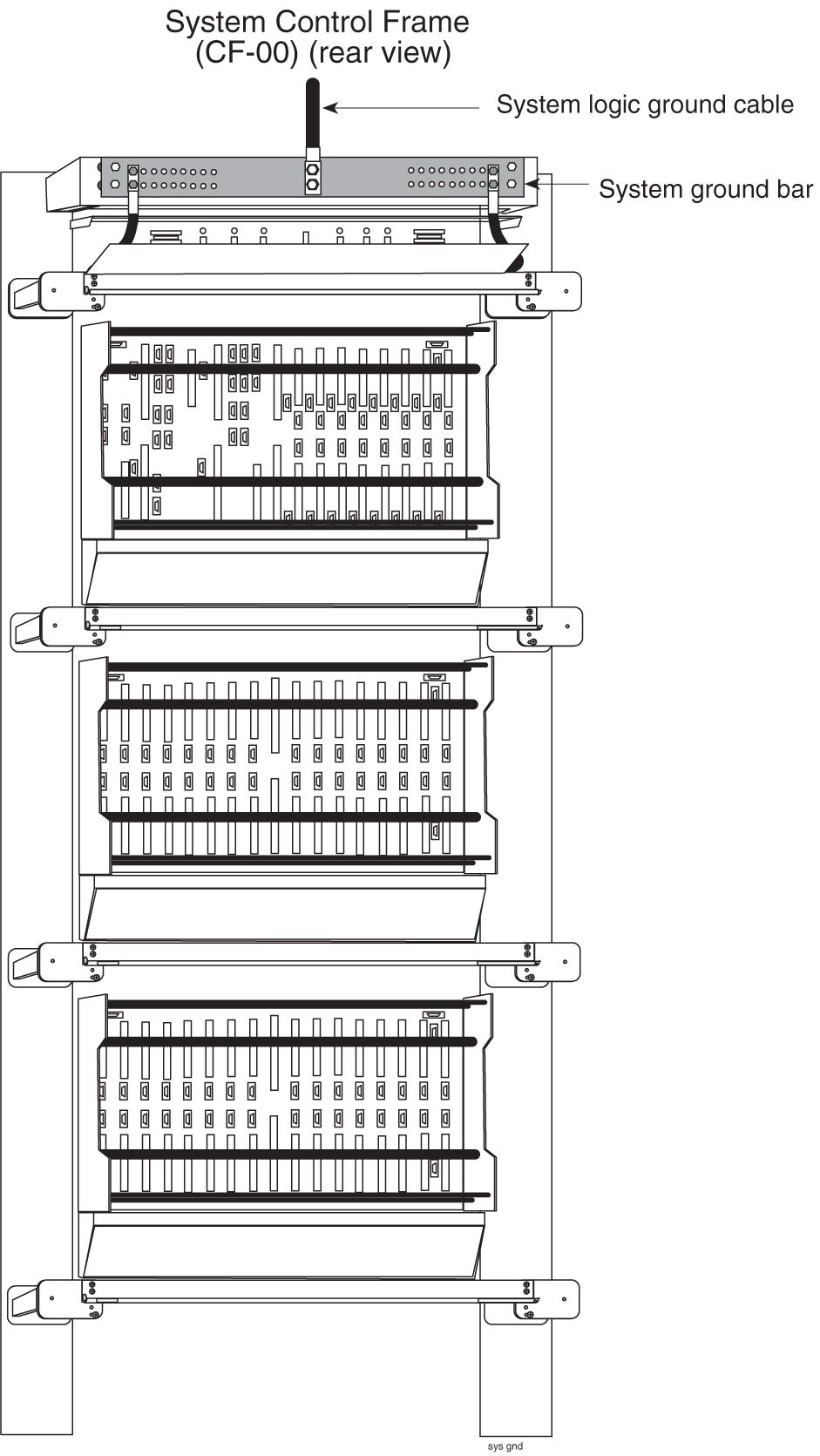
Figure 5-20 System Logic Ground Bar and Cable
Note:
It may be necessary to drill the central office ground window bar to accept the 3/8-inch bolts on one-inch centers. Apply the 145P cable tags (see Figure 5-24) provided to both ends of the ground cable, including the “Do Not Disconnect”. - Install the logic ground cable lugs P/N 804-0817-R02 using the 1/4-inch 20 copper-plated hardware provided (refer to Figure 5-20). Tighten the bolts to 68 inch-pounds.
Figure 5-21 System Logic Grounding
Note:
The only ground cables that are terminated to the system ground bar are the logic grounds from the fuse and alarm panel.Note:
DONOT run Logic Ground or Power Cables on the cable horns in the top middle of a frame. The horn is for Row Alarm Cables only. - Terminate the fuse and alarm panel end of the cable on the terminal strip at the position marked LOGICGROUND.
Figure 5-22 1U Fuse and Alarm Panel Rear (P/N 870-2804-01)
Figure 5-23 3U Fuse and Alarm Panel Rear (P/N 870-2320-03))
5.3.5 Logic Ground Cables
The logic ground cables are a part of the internal power distribution. They provide a ground connection between the backplane of each system shelf and the system ground bar in the Control Frame (CF). The logic ground is connected from each shelf to the fuse and alarm panel by the consolidated power cables, cable #6 AWG (P/N 690-0131-R01), terminal lug (P/N 804-0817-R02), and heat-shrink (P/N 804-0228-01).
Note:
It is a requirement that when mating dissimilar metals non oxidizing grease is used between them as a corrosion inhibitor.- Place lug onto the stripped end of the cable and crimp the lug using embossing dies. The stripped cable must fill lug completely to the end of the barrel of the lug and be visible in the end window of the lug.
Note:
Terminal lug (P/N 804-0817-R02) must have two holes and with a window. The stripped cable must fill lug completely to the end of the barrel of the lug and be visible in the end window of the lug. - DONOT “double lug”: The practice of using one bolt through a lug and the ground bar, and through another lug on the other side of the ground bar, held in place by one nut.A bolt through any nut must show at least two threads beyond the nut but no more than four threads should be showing.
Figure 5-25 System Logic Ground Connection
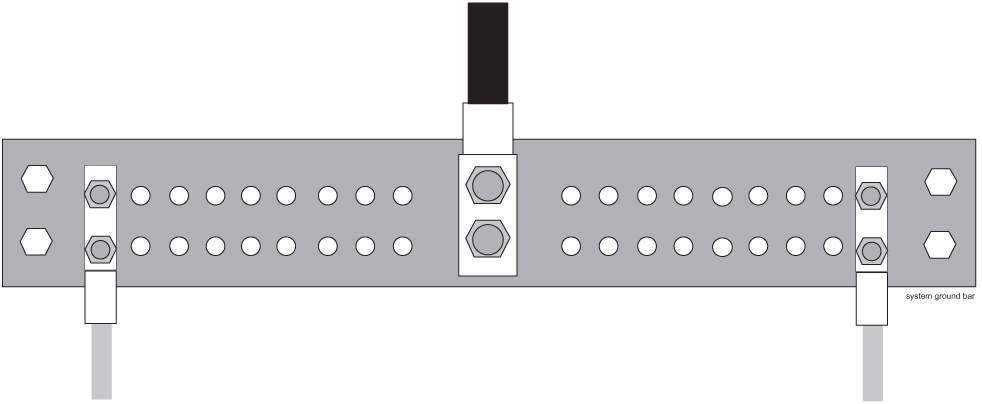
Figure 5-26 Alarm Cable Arm
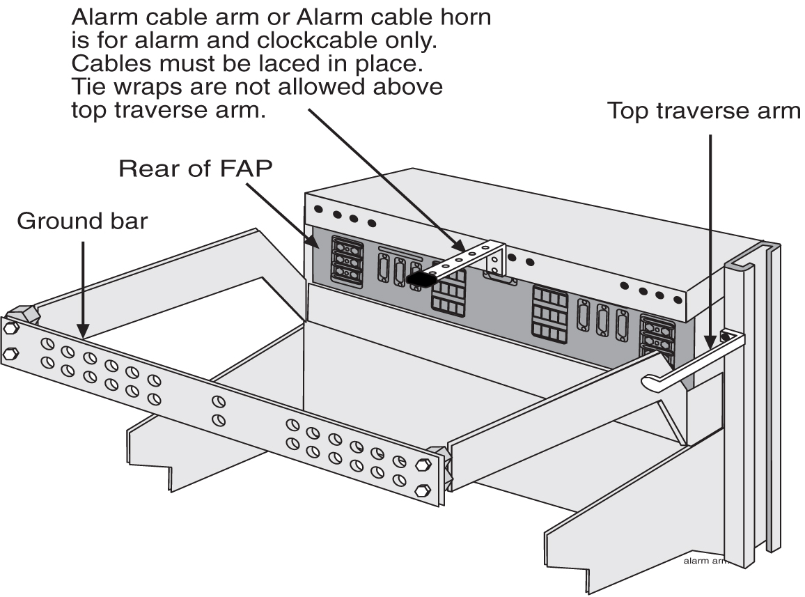
Note:
The alarm cable arm is for alarm cable which maybe a clock cable.
5.4 Fuse Verification
For each fuse location, verify that individual fuse failures affect only the circuits assigned to the specific fuse location.
For those fuse locations that do not yet have circuit cards assigned, use fuses and circuit cards assigned to other locations for the test procedure and then remove them.
Verify each fuse using the following tools:
-
The steps in this procedure to perform the verification.
warning:
Use the antistatic wrist strap connected to the wrist strap grounding point on the frame when performing these procedures. -
Fuse and Card Locations to determine fuse and card locations.
Note:
The card location numbers in the table indicate the shelf and the slot for that card. The left two digits indicate the shelf and the right two digits indicate the card slot in that shelf. For example, a location of 1215 indicates a card in shelf 12, slot 15. -
Figure 5-2 and Figure 5-8 to physically locate the fuse holders.
-
Fuse and Card Locations to physically locate a card in a shelf.
Table 5-10 Fuse Color Codes of Alarm Flags
| Fuse Amp | Fuse Flag Color | Fuse Amp | Fuse Flag Color |
|---|---|---|---|
|
0.18A |
Orange-Red |
2A |
Orange |
|
0.2A |
Black-Red |
2.5A |
White-Orange |
|
0.25A |
Violet |
3A |
Blue |
|
0.33A |
Yellow-Green |
3.5A |
White-Blue |
|
0.375A |
White-Green |
4A |
White -Brown |
|
0.5A |
Red |
5A |
Green |
|
0.65A |
Black |
7.5A |
Black-White |
|
0.75A |
Brown |
10A |
Red-White |
|
1A |
Gray |
12A |
Yellow-Green |
|
1.33A |
White |
15A |
Red-Blue |
|
1.5A |
White-Yellow |
Procedure - Verify Individual Fuse Positions
5.5 Verification of Fuse Alarm Function
This procedure verifies that appropriate fuse alarms are generated by the system.
warning:
Use the antistatic wrist strap connected to the wrist strap grounding point when performing these procedures.- Repeat steps 3 and 4 for fuse bank B of the control
frame and for fuse banks A and B of each extension frame.
Figure 5-27 Fuse (GMT Brand Name)
5.6 FAP Alarm System Test
The following procedure describes system wide fuse alarm testing of the FAP.
5.7 Fuse Assignments
Refer to Installation “Fuse and Card Locations” section for information on the fuse assignments for the Control Frame, CF-00 and five Extension Frames, EF-00 through EF-04.
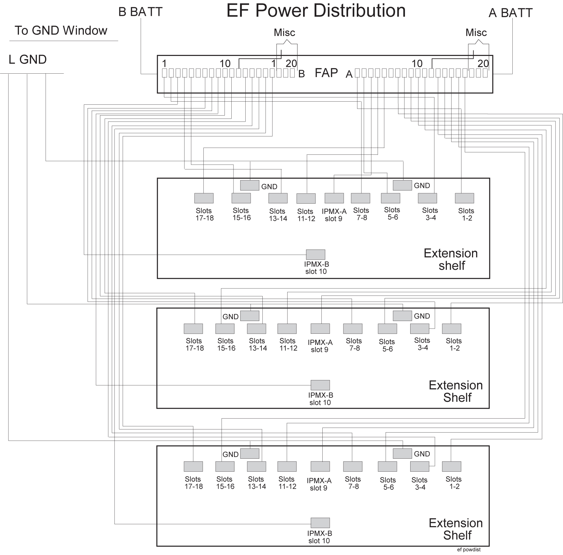
The power distribution for the control frame and the extension frame are shown in the following figures:
- Control frame, Figure 5-28
-
Extension frame, Figure 5-29
Figure 5-28 Control Frame FAP (P/N 870-0243-08 and P/N 870-1606-xx)
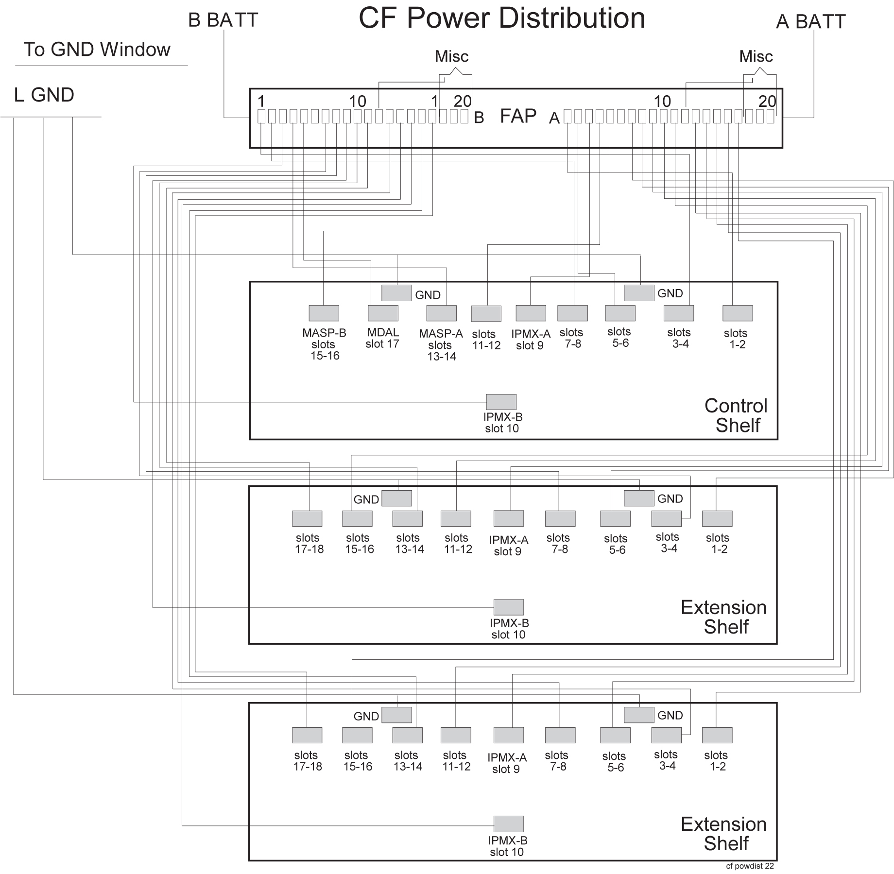
Figure 5-29 Extension Frame FAP (P/N 870-0243-08 and P/N 870-1606-xx)
5.8 Fuse and Card Locations
This section describes fuse assignments for the Control Frame (CF-00) and five Extension Frames (EF-00 through EF-04) are shown.
Table 5-11 Fuses and Card Locations
| Fuse Location/Capacity | Card Location/Type |
|---|---|
|
Control Frame 00 (CF-00) Fuse and Alarm Panel side A (refer to Figure 5-30) |
|
|
Fuse 1A/3Amp |
1101, 1102/LIMs, E/DCM*, or E5-E1T1 |
|
Fuse 2A/3Amp |
1105, 1106/LIMs, E/DCM*, or E1-T1 |
|
Fuse 3A/Amp |
1109 |
|
Fuse 4A/3Amp |
1111, 1112/LIMs, E/DCM*, or E1-T1 |
|
Fuse 5A/3Amp |
1115, 1116/MASP - B and MCAP |
|
Fuse 6A/dummy fuse |
Designated for FAN 3 Amp |
|
Fuse 7A/3Amp |
1201, 1202/LIMs, E/DCM*, or E1-T1 |
|
Fuse 8A/3Amp |
1205, 1206/LIMs, E/DCM*, or E1-T1 |
|
Fuse 9A/1Amp |
1209 |
|
Fuse 10A/3Amp |
1211, 1212/LIMs, E/DCM*, or E1-T1 |
|
Fuse 11A/3Amp |
1215, 1216/LIMs, E/DCM*, or E1-T1 |
|
Fuse 12A/dummy fuse |
Designated for FAN 3 Amp |
|
Fuse 13A/3Amp |
1301, 1302/LIMs, E/DCM*, or E1-T1 |
|
Fuse 14A/3Amp |
1305, 1306/LIMs, E/DCM*, or E1-T1 |
|
Fuse 15A/1Amp |
1309 |
|
Fuse 16A/3Amp |
1311, 1312/LIMs, E/DCM*, or E1-T1 |
|
Fuse 17A/3Amp |
1315, 1316/LIMs, E/DCM*, or E1-T1 |
|
Fuse 18A/dummy fuse |
Designated for FAN 3 Amp |
|
Fuse 19A/dummy fuse |
OPEN |
|
Fuse 20A/dummy fuse |
OPEN |
|
Control Frame 00 (CF-00) Fuse and Alarm Panel side B (refer to Figure 5-30) |
|
|
Fuse 1B/3Amp |
1103, 1104/LIMs, E/DCM*, or E1-T1 |
|
Fuse 2B/3Amp |
1107, 1108/LIMs, E/DCM*, or E1-T1 |
|
Fuse 3B/1Amp |
1110 |
|
Fuse 4B/3Amp |
1113, 1114/MASP - A, and MCAP |
|
Fuse 5B/3Amp |
1117, 1118/HIPR/HIPR2 |
|
Fuse 6B/dummy fuse |
Designated for FAN 3 Amp |
|
Fuse 7B/3Amp |
1203, 1204/LIM, E1-T1, DCM* |
|
Fuse 8B/3Amp |
1207, 1208/LIM, E1-T1, DCM* |
|
Fuse 9B/1Amp |
1210 |
|
Fuse 10B/3Amp |
1213, 1214/LIMs, E/DCM*, or E1-T1 |
|
Fuse 11B/3Amp |
1217, 1218/LIMs, E/DCM*, or E1-T1 |
|
Fuse 12B/dummy fuse |
Designated for FAN 3 Amp |
|
Fuse 13B/3Amp |
1303, 1304/LIMs, E/DCM*, or E1-T1 |
|
Fuse 14B/3Amp |
1307, 1308/LIMs, E/DCM*, or E1-T1 |
|
Fuse 15B/1Amp |
1310 |
|
Fuse 16B/3Amp |
1313, 1314/LIMs, E/DCM*, or E1-T1 |
|
Fuse 17B/3Amp |
1317, 1318/LIMs, E/DCM*, or E1-T1 |
|
Fuse 18B/dummy fuse |
Designated for FAN 3 Amp |
|
Fuse 19B/dummy fuse |
OPEN |
|
Fuse 20B/dummy fuse |
OPEN |
|
Extension Frame 00 (EF-00) Fuse and Alarm Panel side A (refer to Figure 5-31) |
|
|
Fuse 1A/3Amp |
2101, 2102/LIMs, E/DCM*, or E1-T1 |
|
Fuse 2A/3Amp |
2105, 2106/LIMs, E/DCM*, or E1-T1 |
|
Fuse 3A/1Amp |
2109 |
|
Fuse 4A/3Amp |
2111, 2112/ LIMs, E/DCM*, or E1-T1 |
|
Fuse 5A/3Amp |
2115, 2116/LIMs, E/DCM*, or E1-T1 |
|
Fuse 6A/dummy fuse |
Designated for FAN 3 Amp |
|
Fuse 7A/3Amp |
2201, 2202/LIMs, E/DCM*, or E1-T1 |
|
Fuse 8A/3Amp |
2205, 2206/LIMs, E/DCM*, or E1-T1 |
|
Fuse 9A/1Amp |
2209 |
|
Fuse 10A/3Amp |
2211, 2212/LIMs, E/DCM*, or E1-T1 |
|
Fuse 11A/3Amp |
2215, 2216/LIMs, E/DCM*, or E1-T1 |
|
Fuse 12A/dummy fuse |
Designated for FAN 3 Amp |
|
Fuse 13A/3Amp |
2301, 2302/LIMs, E/DCM*, or E1-T1 |
|
Fuse 14A/3Amp |
2305, 2306/LIMs, E/DCM*, or E1-T1 |
|
Fuse 15A/1Amp |
2309 |
|
Fuse 16A/3Amp |
2311, 2312/LIMs, E/DCM*, or E1-T1 |
|
Fuse 17A/3Amp |
2315, 2316/LIMs, E/DCM*, or E1-T1 |
|
Fuse 18A/dummy fuse |
Designated for FAN 3 Amp |
|
Fuse 19A/dummy fuse |
OPEN |
|
Fuse 20A/dummy fuse |
OPEN |
|
Extension Frame 00 (EF-00) Fuse and Alarm Panel side B (refer to Figure 5-31) |
|
|
Fuse 1B/3Amp |
2103, 2104/LIMs, E/DCM*, or E1-T1 |
|
Fuse 2B/3Amp |
2107, 2108/LIMs, E/DCM*, or E1-T1 |
|
Fuse 3B/1Amp |
2110 |
|
Fuse 4B/3Amp |
2113, 2114/LIMs, E/DCM*, or E1-T1 |
|
Fuse 5B/3Amp |
2117, 2118/LIMs, E/DCM*, or E1-T1 |
|
Fuse 6B/dummy fuse |
Designated for FAN 3 Amp |
|
Fuse 7B/3Amp |
2203, 2204/LIMs, E/DCM*, or E1-T1 |
|
Fuse 8B/3Amp |
2207, 2208/LIMs, E/DCM*, or E1-T1 |
|
Fuse 9B/1Amp |
2210 |
|
Fuse 10B/3Amp |
2213, 2214/LIMs, E/DCM*, or E1-T1 |
|
Fuse 11B/3Amp |
2217, 2218/LIMs, E/DCM*, or E1-T1 |
|
Fuse 12B/dummy fuse |
Designated for FAN 3 Amp |
|
Fuse 13B/3Amp |
2303, 2304/LIMs, E/DCM*, or E1-T1 |
|
Fuse 14B/3Amp |
2307, 2308/LIMs, E/DCM*, or E1-T1 |
|
Fuse 15B/1Amp |
2310 |
|
Fuse 16B/3Amp |
2313, 2314/LIMs, E/DCM*, or E1-T1 |
|
Fuse 17B/3Amp |
2317, 2318/LIMs, E/DCM*, or E1-T1 |
|
Fuse 18B/(dummy fuse) |
Designated for FAN 3 Amp |
|
Fuse 19B/dummy fuse |
OPEN |
|
Fuse 20B/dummy fuse |
OPEN |
|
Extension Frame 01 (EF-01) Fuse and Alarm Panel side A (refer to Figure 5-32) |
|
|
Fuse 1A/3Amp |
3101, 3102/LIMs, E/DCM*, or E1-T1 |
|
Fuse 2A/3Amp |
3105, 3106/LIMs, E/DCM*, or E1-T1 |
|
Fuse 3A/1Amp |
3109 |
|
Fuse 4A/3Amp |
3111, 3112/LIMs, E/DCM*, or E1-T1 |
|
Fuse 5A/3Amp |
3115, 3116/LIMs, E/DCM*, or E1-T1 |
|
Fuse 6A/dummy fuse |
Designated for FAN 3 Amp |
|
Fuse 7A/3Amp |
3201, 3202/LIMs, E/DCM*, or E1-T1 |
|
Fuse 8A/3Amp |
3205, 3206/LIMs, E/DCM*, or E1-T1 |
|
Fuse 9A/1Amp |
3209 |
|
Fuse 10A/3Amp |
3211, 3212 /LIMs, E/DCM*, or E1-T1 |
|
Fuse 11A/3Amp |
3215, 3216/LIM, E1-T1, DCM*, or EDCM |
|
Fuse 12A/dummy fuse |
Designated for FAN 3 Amp |
|
Fuse 13A/3Amp |
3301, 3302/LIMs, E/DCM*, or E1-T1 |
|
Fuse 14A/3Amp |
3305, 3306/LIMs, E/DCM*, or E1-T1 |
|
Fuse 15A/1Amp |
3309 |
|
Fuse 16A/3Amp |
3311, 3312/LIMs, E/DCM*, or E1-T1 |
|
Fuse 17A/3Amp |
3315, 3316/LIMs, E/DCM*, or E1-T1 |
|
Fuse 18A/(dummy fuse) |
Designated for FAN 3 Amp |
|
Fuse 19A/dummy fuse |
OPEN |
|
Fuse 20A/dummy fuse |
OPEN |
|
Extension Frame 01 (EF-01) Fuse and Alarm Panel side B (refer to Figure 5-32) |
|
|
Fuse 1B/3Amp |
3103, 3104/LIMs, E/DCM*, or E1-T1 |
|
Fuse 2B/3Amp |
3107, 3108/LIMs, E/DCM*, or E1-T1 |
|
Fuse 3B/1Amp |
3110 |
|
Fuse 4B/3Amp |
3113, 3114/LIMs, E/DCM*, or E1-T1 |
|
Fuse 5B/3Amp |
3117, 3118/LIMs, E/DCM*, or E1-T1 |
|
Fuse 6B/dummy fuse |
Designated for FAN 3 Amp |
|
Fuse 7B/3Amp |
3203, 3204/LIMs, E/DCM*, or E1-T1 |
|
Fuse 8B/3Amp |
3207, 3208/LIMs, E/DCM*, or E1-T1 |
|
Fuse 9B/1Amp |
3210 |
|
Fuse 10B/3Amp |
3213, 3214/LIMs, E/DCM*, or E1-T1 |
|
Fuse 11B/3Amp |
3217, 3218/LIMs, E/DCM*, or E1-T1 |
|
Fuse 12B/(dummy fuse) |
Designated for FAN 3 Amp |
|
Fuse 13B/3Amp |
3303, 3304/LIMs, E/DCM*, or E1-T1 |
|
Fuse 14B/3Amp |
3307, 3308/LIMs, E/DCM*, or E1-T1 |
|
Fuse 15B/1Amp |
3310 |
|
Fuse 16B/3Amp |
3313, 3314/LIMs, E/DCM*, or E1-T1 |
|
Fuse 17B/3Amp |
3317, 3318/LIMs, E/DCM*, or E1-T1 |
|
Fuse 18B/dummy fuse |
Designated for FAN 3 Amp |
|
Fuse 19B/dummy fuse |
OPEN |
|
Fuse 20B/dummy fuse |
OPEN |
|
Extension Frame 02 (EF-02) Fuse and Alarm Panel side A (refer to Figure 5-33) |
|
|
Fuse 1A/3Amp |
4101, 4102/LIMs, E/DCM*, or E1-T1 |
|
Fuse 2A/3Amp |
4105, 4106/LIMs, E/DCM*, or E1-T1 |
|
Fuse 3A/1Amp |
4109 |
|
Fuse 4A/3Amp |
4111, 4112/LIMs, E/DCM*, or E1-T1 |
|
Fuse 5A/3Amp |
4115, 4116/LIMs, E/DCM*, or E1-T1 |
|
Fuse 6A/dummy fuse |
Designated for FAN 3 Amp |
|
Fuse 7A/3Amp |
4201, 4202/LIMs, E/DCM*, or E1-T1 |
|
Fuse 8A/3Amp |
4205, 4206/LIMs, E/DCM*, E5-E1T1, or E5-TSM |
|
Fuse 9A/1Amp |
4209 |
|
Fuse 10A/3Amp |
4211, 4212/LIMs, E/DCM*, or E1-T1 |
|
Fuse 11A/3Amp |
4215, 4216/LIMs, E/DCM*, or E1-T1 |
|
Fuse 12A/dummy fuse |
Designated for FAN 3 Amp |
|
Fuse 13A/3Amp |
4301, 4302/LIMs, E/DCM*, or E1-T1 |
|
Fuse 14A/3Amp |
4305, 4306/LIMs, E/DCM*, or E1-T1 |
|
Fuse 15A/1Amp |
4309 |
|
Fuse 16A/3Amp |
4311, 4312/LIMs, E/DCM*, or E1-T1 |
|
Fuse 17A/3Amp |
4315, 4316/LIMs, E/DCM*, or E1-T1 |
|
Fuse 18A/dummy fuse |
Designated for FAN 3 Amp |
|
Fuse 19A/dummy fuse |
OPEN |
|
Fuse 20A/dummy fuse |
OPEN |
|
Extension Frame 02 (EF-02) Fuse and Alarm Panel side B (refer to Figure 5-33) |
|
|
Fuse 1B/3Amp |
4103, 4104/LIMs, E/DCM*, or E1-T1 |
|
Fuse 2B/3Amp |
4107, 4108/LIMs, E/DCM*, or E1-T1 |
|
Fuse 3B/1Amp |
4110 |
|
Fuse 4B/3Amp |
4113, 4114/LIMs, E/DCM*, or E1-T1 |
|
Fuse 5B/3Amp |
4117, 4118/LIMs, E/DCM*, or E1-T1 |
|
Fuse 6B/(dummy fuse) |
Designated for FAN 3 Amp |
|
Fuse 7B/3Amp |
4203, 4204/LIMs, E/DCM*, or E1-T1 |
|
Fuse 8B/3Amp |
4207, 4208/LIMs, E/DCM*, or E1-T1 |
|
Fuse 9B/1Amp |
4210 |
|
Fuse 10B/3Amp |
4213, 4214/LIMs, E/DCM*, or E1-T1 |
|
Fuse 11B/3Amp |
4217, 4218/LIMs, E/DCM*, or E1-T1 |
|
Fuse 12B/(dummy fuse) |
Designated for FAN 3 Amp |
|
Fuse 13B/3Amp |
4303, 4304/LIMs, E/DCM*, or E1-T1 |
|
Fuse 14B/3Amp |
4307, 4308/LIMs, E/DCM*, or E1-T1 |
|
Fuse 15B/1Amp |
4310 |
|
Fuse 16B/3Amp |
4313, 4314/LIMs, E/DCM*, or E1-T1 |
|
Fuse 17B/3Amp |
4317, 4318/LIMs, E/DCM*, or E1-T1 |
|
Fuse 18B/dummy fuse |
Designated for FAN 3 Amp |
|
Fuse 19B/dummy fuse |
OPEN |
|
Fuse 20B/dummy fuse |
OPEN |
|
Extension Frame 03 (EF-03) Fuse and Alarm Panel side A (refer to Figure 5-34) |
|
|
Fuse 1A/3Amp |
5101, 5102/LIMs, E/DCM*, or E1-T1 |
|
Fuse 2A/3Amp |
5105, 5106/LIMs, E/DCM*, or E1-T1 |
|
Fuse 3A/1Amp |
5109 |
|
Fuse 4A/3Amp |
5111, 5112/LIMs, E/DCM*, or E1-T1 |
|
Fuse 5A/3Amp |
5115, 5116/LIMs, E/DCM*, or E1-T1 |
|
Fuse 6A/(dummy fuse) |
Designated for FAN 3 Amp |
|
Fuse 7A/3Amp |
5201, 5202/LIMs, E/DCM*, or E1-T1 |
|
Fuse 8A/3Amp |
5205, 5206/LIMs, E/DCM*, or E1-T1, |
|
Fuse 9A/1Amp |
5209 |
|
Fuse 10A/3Amp |
5211, 5212/LIMs, E/DCM*, or E1-T1 |
|
Fuse 11A/3Amp |
5215, 5216/LIMs, E/DCM*, or E1-T1 |
|
Fuse 12A/(dummy fuse) |
Designated for FAN 3 Amp |
|
Fuse 13A/3Amp |
5301, 5302/LIMs, E/DCM*, or E1-T1 |
|
Fuse 14A/3Amp |
5305, 5306/LIMs, E/DCM*, or E1-T1 |
|
Fuse 15A/1Amp |
5309 |
|
Fuse 16A/3Amp |
5311, 5312/LIMs, E/DCM*, or E1-T1 |
|
Fuse 17A/3Amp |
5315, 5316/LIM, E1-T1, DCM* |
|
Fuse 18A/(dummy fuse) |
Designated for FAN 3 Amp |
|
Fuse 19A/dummy fuse |
OPEN |
|
Fuse 20A/dummy fuse |
OPEN |
|
Extension Frame 03 (EF-03) Fuse and Alarm Panel side B (refer to Figure 5-34) |
|
|
Fuse 1B/3Amp |
5103, 5104/LIMs, E/DCM*, or E1-T1 |
|
Fuse 2B/3Amp |
5107, 5108/LIMs, E/DCM*, E1-T1, or TSM, |
|
Fuse 3B/1Amp |
5110 |
|
Fuse 4B/3Amp |
5113, 5114/LIMs, E/DCM*, or E1-T1 |
|
Fuse 5B/3Amp |
5117, 5118/LIMs, E/DCM*, E5-E1T1, or E5-TSM |
|
Fuse 6B/(dummy fuse) |
Designated for FAN 3 Amp |
|
Fuse 7B/3Amp |
5203, 5204/LIMs, E/DCM*, or E1-T1 |
|
Fuse 8B/3Amp |
5207, 5208/LIMs, E/DCM*, or E1-T1 |
|
Fuse 9B/1Amp |
5210 |
|
Fuse 10B/3Amp |
5213, 5214/LIMs, E/DCM*, or E1-T1 |
|
Fuse 11B/3Amp |
5217, 5218/LIMs, E/DCM*, or E1-T1 |
|
Fuse 12B/(dummy fuse) |
Designated for FAN 3 Amp |
|
Fuse 13B/3Amp |
5303, 5304/LIMs, E/DCM*, or E1-T1 |
|
Fuse 14B/3Amp |
5307, 5308/LIMs, E/DCM*, or E1-T1 |
|
Fuse 15B/1Amp |
5310 |
|
Fuse 16B/3Amp |
5313, 5314/LIMs, E/DCM*, or E1-T1 |
|
Fuse 17B/3Amp |
5317, 5318/LIMs, E/DCM*, or E1-T1 |
|
Fuse 18B/(dummy fuse) |
Designated for FAN 3 Amp |
|
Fuse 19B/dummy fuse |
OPEN |
|
Fuse 20B/dummy fuse |
OPEN |
|
Extension Frame 04 (EF-04) Fuse and Alarm Panel side A (refer to Figure 5-35) |
|
|
Fuse 1A/3Amp |
6101, 6102/LIMs, E/DCM*, or E1-T1 |
|
Fuse 2A/3Amp |
6105, 6106/LIMs, E/DCM*, or E1-T1 |
|
Fuse 3A/1Amp |
6109 |
|
Fuse 4A/3Amp |
6111, 6112/LIMs, E/DCM*, or E1-T1 |
|
Fuse 5A/3Amp |
6115, 6116/LIMs, E/DCM*, or E1-T1 |
|
Fuse 6A/dummy fuse |
|
|
Fuse 7A/dummy fuse |
|
|
Fuse 8A/dummy fuse |
|
|
Fuse 9A/dummy fuse |
|
|
Fuse 10A/dummy fuse |
|
|
Fuse 11A/dummy fuse |
|
|
Fuse 12A/dummy fuse |
|
|
Fuse 13A/dummy fuse |
|
|
Fuse 14A/dummy fuse |
|
|
Fuse 15A/dummy fuse |
|
|
Fuse 16A/dummy fuse |
|
|
Fuse 17A/dummy fuse |
|
|
Fuse 18A/dummy fuse |
|
|
Fuse 19A/dummy fuse |
|
|
Fuse 20A/dummy fuse |
|
|
Extension Frame 04 (EF-04) Fuse and Alarm Panel side B (refer to Figure 5-35) |
|
|
Fuse 1B/3Amp |
6103, 6104/LIMs, E/DCM*, or E1-T1 |
|
Fuse 2B/3Amp |
6107, 6108/LIMs, E/DCM*, or E1-T1 |
|
Fuse 3B/1Amp |
6110 |
|
Fuse 4B/3Amp |
6113, 6114/LIMs, E/DCM*, or E1-T1 |
|
Fuse 5B/3Amp |
6117, 6118/LIMs, E/DCM*, or E1-T1 |
|
Fuse 6B/dummy fuse |
|
|
Fuse 7B/dummy fuse |
|
|
Fuse 8B/dummy fuse |
|
|
Fuse 9B/dummy fuse |
|
|
Fuse 10B/dummy fuse |
|
|
Fuse 11B/dummy fuse |
|
|
Fuse 12B/dummy fuse |
|
|
Fuse 13B/dummy fuse |
|
|
Fuse 14B/dummy fuse |
|
|
Fuse 15B/dummy fuse |
|
|
Fuse 16B/dummy fuse |
|
|
Fuse 17B/dummy fuse |
|
|
Fuse 18B/dummy fuse |
|
|
Fuse 19B/dummy fuse |
|
|
Fuse 20B/dummy fuse |
|
|
Fuse 2A |
|
|
Fuse 3A/dummy fuse |
|
|
Fuse 4A/dummy fuse |
|
|
Fuse 5A/dummy fuse |
|
|
Fuse 6A/dummy fuse |
|
|
Fuse 7A/dummy fuse |
|
|
Fuse 8A/dummy fuse |
|
|
Fuse 9A/dummy fuse |
|
|
Fuse 10A/dummy fuse |
|
|
Fuse 11A/dummy fuse |
|
|
Fuse 12A/dummy fuse |
|
|
Fuse 13A/dummy fuse |
|
|
Fuse 14A/dummy fuse |
|
|
Fuse 15A/dummy fuse |
|
|
Fuse 16A/dummy fuse |
|
|
Fuse 17A/dummy fuse |
|
|
Fuse 18A/dummy fuse |
|
|
Fuse 19A |
(10 A) A power (FAP P/N 870-2320-03 for heavy duty frame) |
|
Fuse 20A |
(10 A) A power (FAP P/N 870-2320-03 for heavy duty frame) |
|
Fuse 3B/dummy fuse |
|
|
Fuse 4B/dummy fuse |
|
|
Fuse 5B/dummy fuse |
|
|
Fuse 6B/dummy fuse |
|
|
Fuse 7B/dummy fuse |
|
|
Fuse 8B/dummy fuse |
|
|
Fuse 9B/dummy fuse |
|
|
Fuse 10B/dummy fuse |
|
|
Fuse 11B/dummy fuse |
|
|
Fuse 12B/dummy fuse |
|
|
Fuse 13B/dummy fuse |
|
|
Fuse 14B/dummy fuse |
|
|
Fuse 15B/dummy fuse |
|
|
Fuse 16B/dummy fuse |
|
|
Fuse 17B/dummy fuse |
|
|
Fuse 18B/dummy fuse |
|
|
Fuse 19B |
(10 A) B power (FAP P/N 870-2320-03) |
|
Fuse 20B |
(10 A) B power (FAP P/N 870-2320-03) |
5.9 Card Locations in Control and Extension Shelves
Figure 5-30 through Figure 5-35 show the card locations in Control and Extension shelves.
Figure 5-30 shows the numbering of the shelves, with the shelf identification DIP switch settings and backplane wiring, and card locations on theControl Frame (CF) and Extension Frame (EF).
Figure 5-30 Control Frame CF-00 Numbering Plan
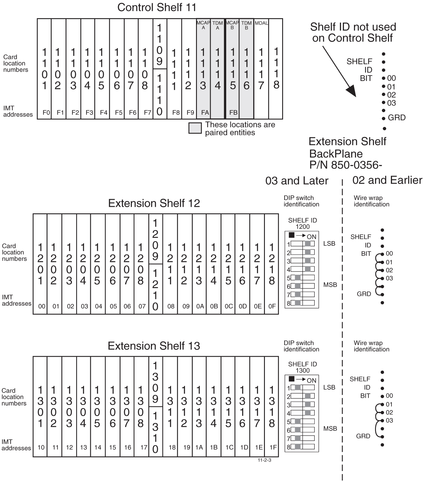
The Extension Frame (EF) accommodates up to three extension shelves, each shelf capable of supporting up to 16 Link Interface Module (LIMs) or Translation Service Module (TSMs) in any combination.
The system is delivered with customer-specific locations for the Database Communications Module (DCM.
Note:
For EAGLE only, the insertion of a DCM card requires an odd-numbered slot.The entire system can have up to five Extension Frames, EF-00 to EF-04. EF-04 supports only one extension shelf.
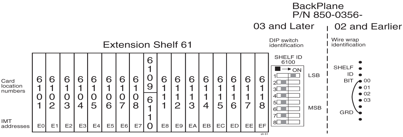
Figure 5-31 through Figure 5-35 show the numbering of the card locations on the extension frames. Along with shelf DIP switch settings and ID wire wrap.
Figure 5-31 Extension Frame EF-00 Numbering Plan

Figure 5-32 Extension Frame EF-01 Numbering Plan
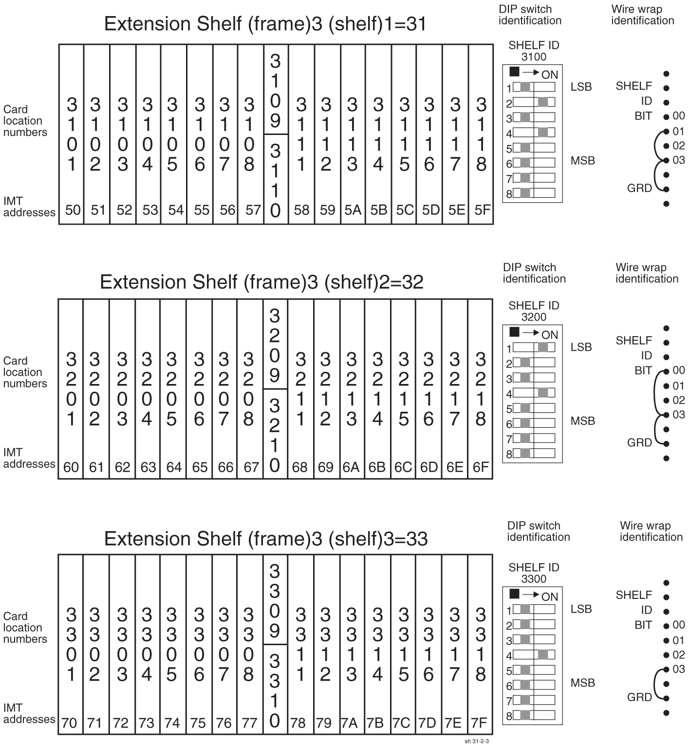
Figure 5-33 Extension Frame EF-02 Numbering Plan
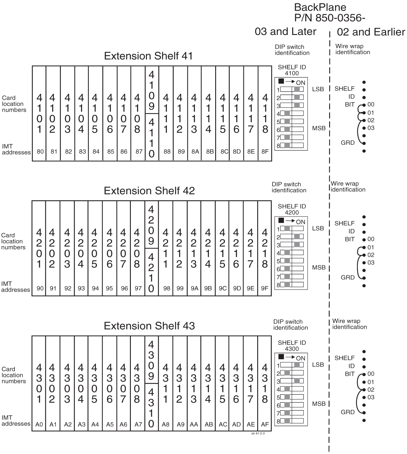
Figure 5-34 Extension Frame EF-03 Numbering Plan
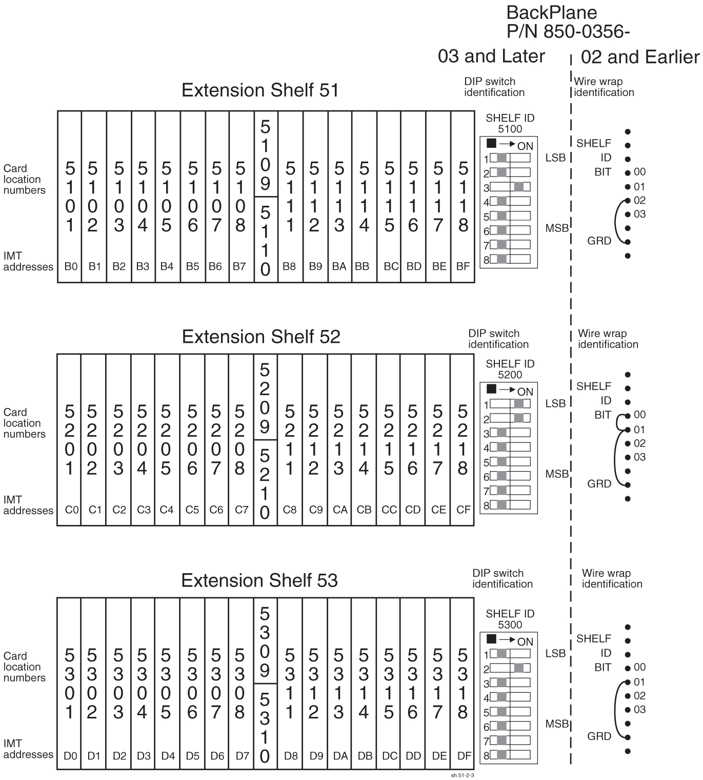
Figure 5-35 Extension Frame EF-04 Numbering Plan