9.2 EMS Configuration Component
Use the following procedures to manage TekPath or ELAP EMS configuration components:
9.2.1 Creating an EMS Configuration Component
For each network element to be supported by the LSMS, create an EMS Configuration component using the following procedure:
Note:
For each EMS configuration created, you must perform a bulk download to the associated EMS/network element. Refer to the LNP Database Synchronization User's Guide for bulk loading procedures.- From the LNP System menu, shown in the following figure:
Figure 9-27 LNP System Menu – Create EMS

, select .
The EMS Configuration Component window displays. The window usually opens with the Address Info tab displayed; if the Address Info tab is not displayed, click its tab to display it.
Figure 9-28 Create LNP System EMS Address Info Tab

- Click the Component Info tab, shown in Figure 9-30.
Figure 9-29 Create LNP System EMS Component Info

- Click the Contact Info tab, shown in Figure 9-29.
Figure 9-30 Create LNP System EMS Contact Info

- When finished, click OK to apply the changes.
-
If the Update Successful dialog, Figure 9-31 appears, click OK. The GUI returns to the main console window.
Figure 9-31 Update Successful Dialog

-
When a mandatory field is empty or a field is not properly configured, the Field Required Figure 9-32 dialog displays.
Figure 9-32 Field Required Dialog

Click OK and correct the appropriate field.
Repeat this step until you receive an Update Successful notification.
-
9.2.2 Modifying an EMS Configuration Component
To modify an existing EMS configuration component, use the following procedure.
Note:
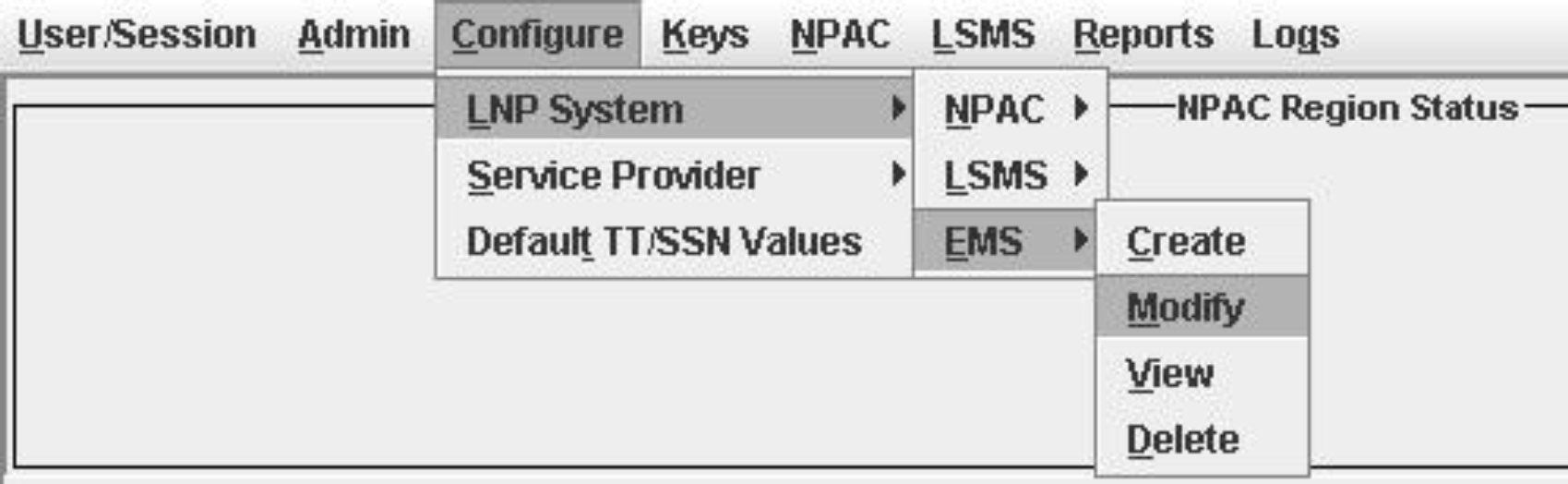
For each EMS configuration created, you must perform a bulk download to the associated EMS/network element. Refer to the LNP Database Synchronization User's Guide for bulk loading procedures.- From the Main Menu, select , as shown in Figure 9-33.The Modify LNP System EMS window, Figure 9-34, appears.
Figure 9-33 LNP System Menu – Modify EMS
 The window usually opens with the Address Info tab displayed; if the Address Info tab is not displayed, click its tab to display it.
Figure 9-34 Modify LNP System EMS Window
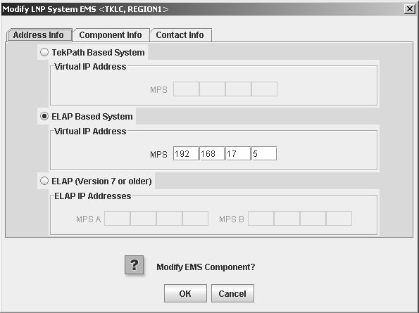
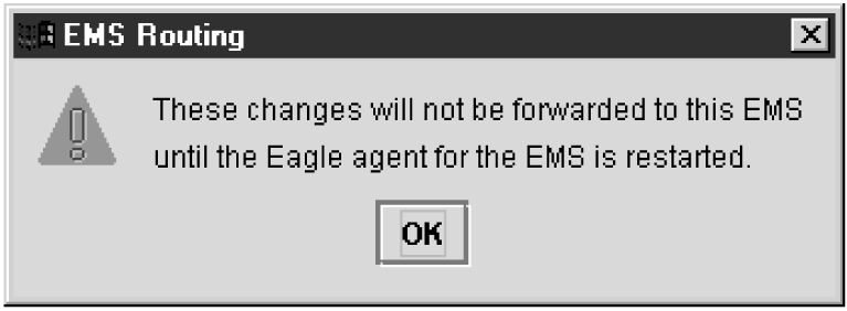
- Click OK.The EMS Routing dialog appears, Figure 9-35 .Click OK.
Figure 9-35 EMS Routing Dialog
The Update Successful dialog displays, Figure 9-36.
Figure 9-36 Update Successful Dialog
Figure 9-37 More Fields Needed Dialog
Click OK and correct the appropriate field.
Repeat this step until you receive an Update Successful notification.
Note:
Changes do not take effect until theeagleagent is restarted (refer to "Manually Verifying and Restarting the Eagle Agents" in the Alarms and Maintenance Guide).
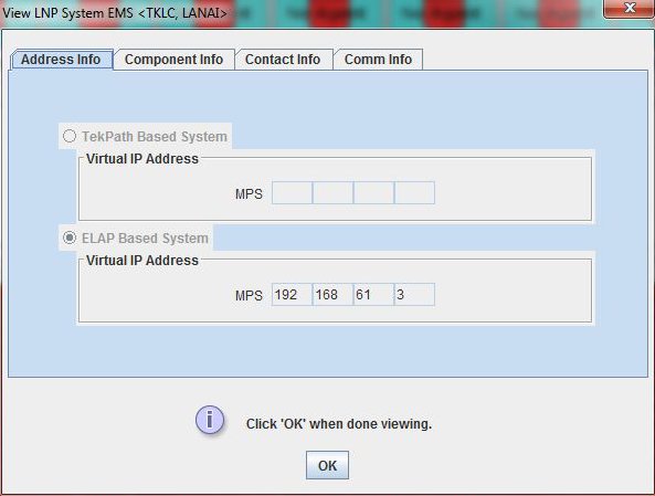
9.2.3 Viewing an EMS Configuration Component
To view EMS configuration component information, use the following procedure.
- From the Main Menu, select .
9.2.4 Deleting an EMS Configuration Component
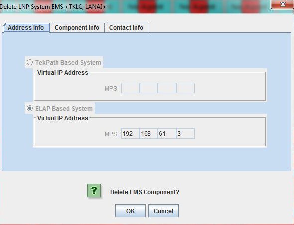
To delete an EMS configuration component, use the following procedure.
- From the Main Menu, select .
- Click OK or Cancel.
- If you click Cancel, you are returned to the LSMS console window.
- If you click OK, the Update Successful dialog displays, Figure 9-40.
Figure 9-40 Update Successful Dialog