Create and Deploy on VMware®

This section provides detail on deploying Oracle Communications Session Delivery products over the ESXI hypervisor and assumes VMware 6. The section also assumes the user understands deployment in these environments and that the majority of deployment tasks, from hardware installation and startup to VM resource and management setup, is complete.

For information on VMware 6, which is also supported, refer to the following link.

https://www.vmware.com/support/pubs/vsphere-esxi-vcenter-server-6-pubs.html

Before You Begin:

  • Confirm that the VMware version 6 Hypervisor is installed on an appropriate network server.
  • Confirm that the server has 40GB of space for this installation.

Note:

The following procedure describes a typical deployment. The system may display different screens, depending on the deployment.

Detail on Oracle Communications Session Delivery product-specific setup steps is shown below.
  1. On the vSphere Client application Home page, go to File, Deploy OVF Template File.
  2. On the Source screen, browse to the target .ova file, and click Next.
  3. On the End User License Agreement screen, click Accept and click Next.
  4. On the Name and Location screen, do the following and click Next.
    • Name. Enter a name for the template.
    • Inventory Location. Select the location where you want to deploy the template.
  5. On the Host / Cluster screen, select the host or cluster where you want to run the deployed template, and click Next.
  6. If applicable to your deployment, select the resource, from the Resource Pool screen, in which you want to deploy this template, and click Next.
  7. On the Storage screen, select the destination storage for the virtual machine files, and click Next.
  8. On the Disk Format screen, select Thick Provisioned Lazy Zeroed, and click Next.
  9. On the Network Mapping screen, map the networks used in this template to networks in your inventory, and click Next.
    The OC-SDP enumerates and binds network interfaces in the order presented by the hypervisor to the virtual machine. If 3 or less interfaces are presented, the bind order is wancom0, s0p0, s1p0. If more than 3 interfaces are presented, the bind order is:
    1. wancom0
    2. wancom1
    3. wancom2
    4. spare
    5. s0p0
    6. s1p0
    7. s0p1
    8. s1p1
    If your hypervisor randomly allocates addresses for network interfaces, the interface order at the hypervisor does not necessarily match that at the OC-SDP. You can use the interface-mapping show command to determine the MAC address to interface order, and if necessary, adjust it using the interface-mapping swap command.
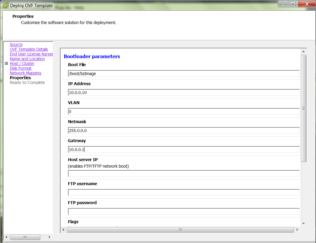
  10. On the properties screen, enter parameters per your configuration, and click Next.

    Figure 5-1 Properties Dialog for OVF Deployment

    This image displays the Deploy OVF Template dialog box's Bootloader parameters.

    Note:

    Do not enter plaintext values in the password fields.
  11. On the Ready to Complete screen, review the selections, and do one of the following:
    • Edit a previous screen by way of the Back button.
    • When the edits are completed, or if no edits are required, click Finish

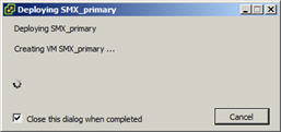
    The system displays the Deploying screen.

    Figure 5-2 OVF Deployment Status Dialog

    This image is a screenshot that shows the Deploying screen.
    When the Deploying screen closes, VM creation and deployment is completed.