14 Channelized Connectivity
This chapter explains how to use Oracle Communications Unified Inventory Management (UIM) to implement channelized connectivity. Channelized connectivity is one of several types of connectivity supported by UIM. See "Connectivity Overview" for an introduction.
About Channelized Connectivity
Several different telecommunications technologies break larger-bandwidth signals into multiple smaller-bandwidth signals or channels that can be used independently. This process is called multiplexing.
You use Channelized Connectivity entities to represent channelized connectivity in UIM. Channelized Connectivity entities are based on Connectivity specifications in which the Connectivity Classification is set to Multiplexed. UIM provides specialized features that support various multiplexing technologies, including:
-
SONET (Synchronous Optical Network)
-
SDH (Synchronous Digital Hierarchy)
-
WDM (Wavelength Division Multiplexing)
-
T-Carrier (TDM carrier)
-
E-Carrier (European TDM carrier)
-
J-Carrier (Japanese TDM carrier)
Each of these technologies defines a hierarchy of possible channel arrangements that provide varying bandwidth capacities.
UIM cartridges supply several Channelized Connectivity specifications that you can use or modify. The OracleComms_UIM_Channelized cartridge includes specifications for PDH, SDH, SONET, TDM, and WDM connectivities. You can also create your own Channelized Connectivity specifications.
Note:
In releases previous to UIM 7.3, all channelized connectivity entities were based on the same specification, TDM Facility. As part of the migration to UIM 7.3 or later, all entities based on TDM Facility are converted to use the Channelized Facility specification that is supplied in the ora_uim_base_specifications cartridge. In addition, you can use Design Studio to create additional Channelized Connectivity specifications. See UIM Cartridge Guide for more information about base cartridges. See Design Studio Help for information about creating specifications.
About Channel Identifiers
Channelized Connectivity entities use the location-based connectivity identifier format. (See "Location-Based Connectivity Identifiers" for more information.) Individual channels also use this format, with the addition of unit values for the channels.Unit values are based on the address of the channel in the signal structure of its parent facility.
Different technologies determine the addresses in different ways depending on their multiplexing schemes. See the following sections and UIM Information Model Reference for additional information about the signal architectures of the various technologies and about channel addresses.
E-Carrier, J-Carrier, and T-Carrier Channel Identifiers
E-Carrier, J-Carrier, and T-Carrier facilities can be channelized to only one level, so channels are numbered sequentially. For example, in a T-Carrier DS1 facility, DS0 channels are addressed sequentially starting at 1 and ending at 24. The 24th DS0 channel in a DS1 facility could have the identifier
PLANTXUSXA.A01 / PLANTXUSXA.K01 / DS1 / T1 / 99 / 24
as an example.
SONET Channel Identifiers
The SONET signal/channel addressing format combines the indexes of each STS-n, VT Group, and VT-n starting from the first signal level to which the SONET facility was configured. Signal level index numbers are separated by a dash.
Figure 14-1 displays the possible index values for each level in the SONET signal architecture.
Figure 14-1 SONET Signal Level Index Values
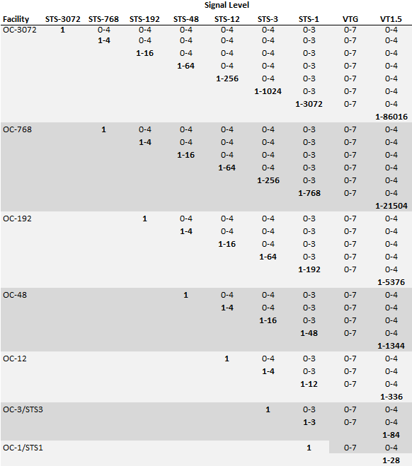
Description of "Figure 14-1 SONET Signal Level Index Values"
For example:
-
15-2-3-6-4 is a VT-1.5 channel in an OC-192 facility (STS-12: 15, STS-3: 2, STS-1: 3, VT Group: 6, VT-1.5: 4)
-
12-0-0-0 is an STS-3 channel in an OC-45 facility (STS-3: 12, STS-1: 0, VT Group: 0, VT-1.5: 0)
-
1-0-0-0 is an STS-3 channel in an OC-3 facility (STS-3: 1, STS-1: 0, VT Group: 0, VT-1.5: 0)
SDH Channel Identifiers
SDH channel identifiers are in the following format:
J-K-L-M
where:
J is the AUG-1 index (from 1 to 1024)
K is the TUG-3 index (from 1 to 3)
L is the TUG-2 index (from 1 to 7)
M is the TU-n index (from 1 to 4)
Each index is always included in the address and is set to 0 if not applicable.
For example:
3-0-0-0 is the address for a VC-4 channel in the third AUG-1 on an STM-4 facility, channelized above the TUG and TU signals.
13-2-1-4 is the address for a VC-11 channel on an STM-16 facility: the thirteenth AUG-1, the second TUG-3, the first TUG-2, the fourth VC-11 on the TUG-2.
Terminating Channels
Like other UIM connectivities, channelized connectivity must be terminated. See "About Termination" for an overview. In addition, the multiplexed channels provided by channelized connectivity must also be terminated.
When you terminate a parent connectivity on a device interface, its channels are automatically terminated on sub-interfaces of that interface if it provides enough sub-interfaces to terminate all the channels. (Sub-interfaces are created automatically only if the Device Interface specifications for the sub-interfaces are related to the parent Device Interface specifications with a minimum and maximum value equal to the number of sub-interfaces at that level.)
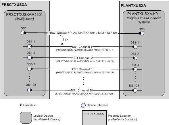
Figure 14-2 shows the FRSCTXUSXA / PLANTXUSXA.K01 / DS3 / T3 / 101 connectivity and its channels. The DS1 channels are provided by the connectivity. The channels terminate on the sub-interfaces of the interfaces on which the connectivity terminates. The sub-interfaces are created automatically by UIM (if the device interface specification includes sub-interfaces).
Device Interfaces and Channel Termination
As shown in Figure 14-2, UIM can automatically terminate channels on sub-interfaces of the device interfaces on which a facility is terminated. But for this functionality to work properly, the logical device and device interface hierarchy must be structured to match the channel hierarchy of the facility. The logical devices must include interfaces and sub-interfaces for all the channels that a connectivity can provide, even if you do not plan to use all of the channels.
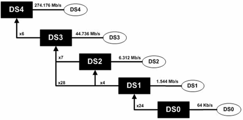
For T-Carrier and similar technologies, the basic relationship between the device interface hierarchy and the channel hierarchy is very direct. Figure 14-3 illustrates the signal hierarchy for the T-Carrier technology.
Figure 14-4 illustrates the hierarchy of channels that a connectivity requires to represent a T1 facility. The DS1 device interfaces on which the facility is terminated must include 24 DS0 sub-interfaces on which to terminate the channels.
Figure 14-4 DS1 Channel and Device Interface Hierarchy
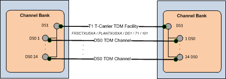
Description of "Figure 14-4 DS1 Channel and Device Interface Hierarchy"
A T3 scenario is slightly more complicated because a T3 can be multiplexed in two ways. The signal can be multiplexed in two stages into 7 DS2 signals each of which is multiplexed to 4 DS1 signals. Alternatively, the signal can be multiplexed directly to 28 DS1 signals, bypassing the intermediate DS2 signals.
In practice, DS2 is an internal multiplexing function and DS2 signals are not exposed externally. As a result, it is not necessary to include DS2 sub-interfaces when you design a device interface hierarchy for a T3 facility.
Figure 14-5 DS3 Channel and Device Interface Hierarchy
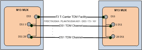
Description of "Figure 14-5 DS3 Channel and Device Interface Hierarchy"
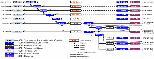
SONET and SDH have more complex signal hierarchies. For example, SDH includes STM-n, AUG-n, AU-n, TUG-n, TU-n, VC-n and C-n signals. All of these are included in the UIM signal architecture. Figure 14-6 illustrates the SDH signal hierarchy.
When you set up a hierarchy of device interfaces to support an SDH facility, however, you need to include only the interfaces on which channels are actually terminated. These interfaces include VC4, VC3, VC12, and so on. These are the interfaces that are interconnected to other interfaces when an enabling connectivity is passed through a logical device. Figure 14-7 illustrates the channel and device interface hierarchy for an STM1 facility.
Note:
For visual clarity, some elements of the hierarchy have been omitted.
Figure 14-7 STM1 Channel and Device Interface Hierarchy
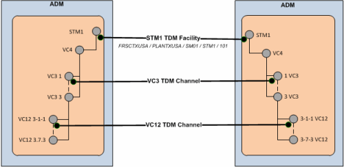
Description of "Figure 14-7 STM1 Channel and Device Interface Hierarchy"
In a more complex STM16 scenario, you may need to design the device interface hierarchy to include possible channel signal levels such as VC4-16c and VC-4-4c, even if you do not expect to use them. (If you definitely do not plan to use the VC4-x levels you can omit those interfaces.) Figure 14-8 illustrates the channel and device interface hierarchy for an STM16 facility. This example includesVC4 and VC3 channels that are terminated on their respective interfaces.
Relative to the full SDH signal hierarchy, the channel and device interface hierarchy is relatively flat because processing and multiplexing signals are not present as interfaces.
Note:
For visual clarity, some elements of the hierarchy have been omitted.
Figure 14-8 STM16 Channel and Device Interface Hierarchy
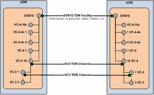
Description of "Figure 14-8 STM16 Channel and Device Interface Hierarchy"
Figure 14-9 illustrates an even more complex STM64 example with VC4-16c, VC-4-4c and VC4 channels terminated on their respective interfaces.
Note:
For visual clarity, some elements of the hierarchy have been omitted.
Figure 14-9 STM64 Channel and Device Interface Hierarchy
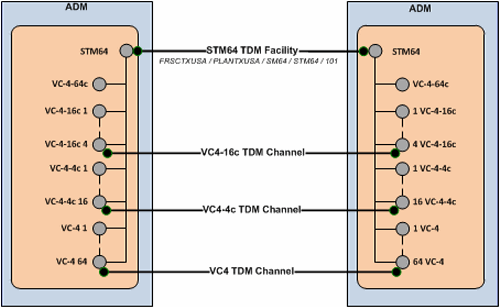
Description of "Figure 14-9 STM64 Channel and Device Interface Hierarchy"
About the UIM Signal Architecture
In both Pipe entities and Connectivity Entity entities, a signal structure defines the multiplexing hierarchy that allows a signal to be broken into lower-data-rate channels. A signal structure is defined through a hierarchy of signal specifications that defines the multiplexing hierarchy of pipe or channelized connectivity. See "Understanding Signal Structures" for more information about signal structures.
For Connectivity entity entities, signal structures are defined by a set of Oracle-provided specifications known as the UIM signal architecture. The signal architecture determines the multiplexing options when you configure channels for a channelized connectivity.
The rate code associated to a channelized connectivity determines the Connectivity Signal Termination Point specification for the facility (root) signal in the signal hierarchy. Connectivity Signal Termination Point specifications and Processing Signal specifications are hierarchically related in the UIM signal architecture to define the multiplexing options for the facility signal. You configure the channels of the channelized connectivity based on the multiplexing options defined by the signal architecture. Based on your configuration choices, UIM creates a signal structure that includes entities representing the signals. The signal hierarchy is displayed in the Channels tab for the channelized connectivity.
The signal architecture also defines compatible signal relationships that enable channelized connectivity to be transported on the channels of SONET and SDH facilities. The rate code of the transported connectivity can differ from the rate code of its assigned channel as long as the channel's signal is compatible with the signal of the connectivity that rides the channel. For example, in SONET, the VT-1.5 SPE channel signal, which has a VT1.5 rate code, is compatible with a DS1 signal. That means that a channelized connectivity with a DS1 rate code can ride a VT-1.5 channel on a SONET facility, such as an OC-3 facility.
The signal architecture is supplied in the ora_uim_basetechnologies cartridge. You can view the contents of this cartridge in Design Studio, but you cannot change it or add specifications. See the Design Studio for UIM Help for more information.
See "E-Carrier Signal Architecture" and "SONET Signal Architecture" for two examples. See UIM Information Model Reference for detailed information about the specifications, entities, and relationships involved in the signal architecture.
E-Carrier Signal Architecture
The E-Carrier signal architecture includes six Signal Termination Point specifications (E5 through E0). Each of these specifications is associated to a rate code that identifies the technology and bit rate for the signal.
With the exception of the E3 signal, each E-Carrier signal can be channelized only to the signal below it in the hierarchy. For example, an E4 transmission facility can only have four E3 channels.
An E3 signal can be multiplexed in two ways: it can multiplex to either four E2 signals or sixteen E1 signals. The signal multiplexes directly from the E3 to the E1 signal without including E2 signals.
Figure 14-10 illustrates the hierarchy of specifications that comprise the E-Carrier signal architecture.
Figure 14-10 E-Carrier Signal Architecture
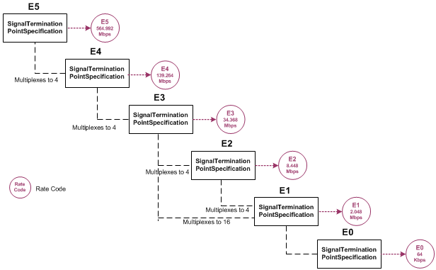
Description of "Figure 14-10 E-Carrier Signal Architecture"
When you associate a rate code to a Connectivity entity, you determine the signal that applies to the facility represented by the entity and also determine its multiplexing options. For example, if you create a Connectivity entity with the E4 rate code, the facility can be muliplexed only to E3 channels.
SONET Signal Architecture
SONET is a multiplexing technology that enables a carrier signal to transport lower-rate traffic from a variety of sources within one transmission frame.
The signal architecture for SONET includes optical carrier Signal Termination Point specifications that define facility signals such as OC-1 and OC-3. The signal architecture also includes corresponding rate codes that you can associate to Channelized Connectivity entities to define their facility signals and signal structures. Channel signals are defined by STS-n SPE (synchronous payload envelope) and VT-n SPE specifications.
The SONET technology uses processing signals to multiplex and align other signals. The signal architecture includes three Processing Signal specifications:
-
Synchronous Transport Signals (STS-n)
-
Virtual Tributary Group (VT Group)
-
Virtual Tributary (VT-n)
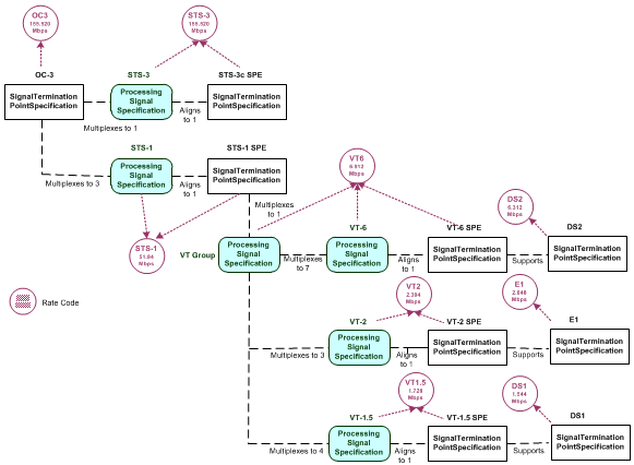
STS-3 and STS-1 signals can serve as both facility signals and processing signals. They are facility signals when used directly on a channelized connectivity. They are processing signals when they multiplex from an OC-n or another STS-n signal. The signal architecture includes specifications for these signals as both Signal Termination Point and Processing Signal specifications.
Figure 14-11 shows the UIM entities and relationships that comprise an OC-3 signal structure. This is the signal structure that is associated to a channelized connectivity when you assign it the OC-3 rate code. See UIM Information Model Reference for more information.
Wavelength Division Multiplexing Signal Architecture
Wavelength Division Multiplexing (WDM) is an optical technology used to increase bandwidth over existing fiber optic backbones. WDM works by combining and transmitting multiple signals simultaneously at different wavelengths on the same fiber. WDM-based networks can transmit data in SONET, SDH, or Ethernet, and can handle the latest bit rate speeds.
UIM supports WDM as channelized connectivity, including the ability to carry SONET, SDH, and Ethernet in WDM channels. The ora_uim_basetechnologies cartridge defines the signal hierarchy and rate codes supported by WDM. It also defines compatibility between WDM rate codes and other rate codes.
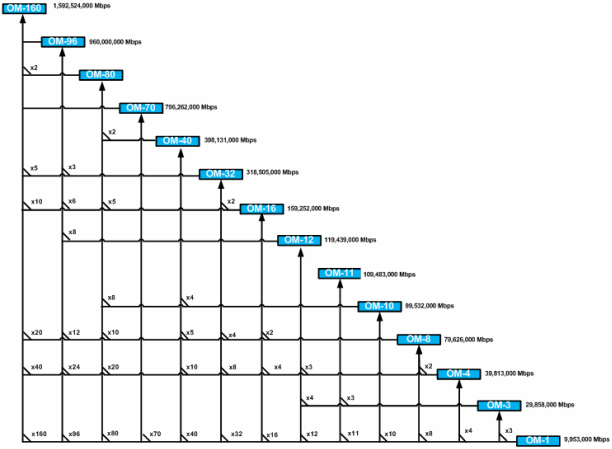
You can create WDM channelized connectivities with rate codes from OM160 through OM4. The signal architecture defined by the WDM cartridge determines how connectivities can be channelized. Figure 14-12 illustrates the WDM signal architecture. For example, the illustration shows that an OM-32 connectivity can be channelized as 2 OM-16 channels, 4 OM-8 channels, 8 OM-4 channels, or 32 OM-1 channels.
You can use WDM channels to enable other connectivities. For example, you can enable an OC192 SONET facility with an OM1 (10 Gbps) channel or a 100 Gbps Ethernet pipe with an OM10 channel.
Note:
Only a TDM facility with a transmission signal type of Optical can be enabled with a WDM channel.
Optical Transport Network Signal Architecture
Optical transport network (OTN) is a series of standards created to combine the benefits of SONET/SDH with the bandwidth-expanding capabilities of Wave Division Multiplexing (WDM). This combination makes it possible to build more network functionality into optical networks. OTN is able to carry many types of data, including 100 GigE signals.
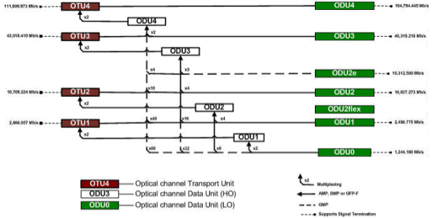
OTN includes two sets of information structures: Optical Transport Unit (OTU) and Optical Data Unit (ODU). OTUs are channelized into ODUs. Figure 14-13 illustrates the OTN signal structure.
Table 14-1 lists the signals supported by ODU channels.
Table 14-1 ODU Channel Signal Support
| ODU Channel | Supported Signals |
|---|---|
|
ODU0 |
1GigE, STM-1, STM-4, OC-3, OC-12, FC1G |
|
ODU1 |
1GigE, STM-1, STM-4, STM-16, OC-3, OC-12, OC-48, FC2G |
|
ODU2 |
10GigE, STM-64, OC-192 |
|
ODU2e |
10GigE, FC10G |
|
ODU3 |
40GigE, STM-256, OC-768 40GigE |
|
ODU3e2 |
ODU2e |
|
ODU4 |
100GigE |
OTN Example
This example illustrates the use of an OTN to enable a 1GigE Ethernet connectivity. The Ethernet connectivity is enabled by an ODU1 channel in an OTU4 facility. The OTN connectivity is itself enabled by an OM10 channel from an OM40 WDM facility. Figure 14-14 and Figure 14-15 show the schematic view of the Connectivity Design tabs of the Ethernet and WDM connectivities.
Figure 14-14 Schematic View of 1GigE Connectivity Enabled by OTN Connectivity
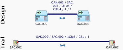
Description of "Figure 14-14 Schematic View of 1GigE Connectivity Enabled by OTN Connectivity"
Figure 14-15 Schematic View of OTU4 Connectivity Enabled by WDM Connectivity
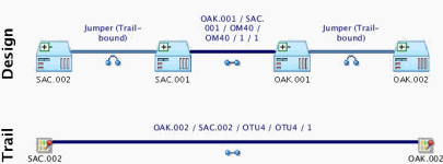
Description of "Figure 14-15 Schematic View of OTU4 Connectivity Enabled by WDM Connectivity"
Configuring Connectivity Capacity
The signal structure of a channelized connectivity is determined by the rate code you assign it. In cases where there are no options about channelization, the first level of channels is created automatically. For example, if you create an E4 connectivity, four E3 channels are created automatically.
For rate codes that include multiple possible signal structures and for channels below the first level in all signal structures, you must configure the capacity of the Channelized Connectivity entity. For example, if you create a DS3 connectivity, you must choose whether to configure the signal structure to include DS2 channels or to skip that level and include DS1 channels directly below the DS3.
You view and configure the signal structure of a Channelized Connectivity entity in the Capacity tab of the Connectivity Details page. Figure 14-16 shows the Capacity tab of a DS3 connectivity that has been multiplexed to 28 DS1 channels. (Only eight of the channels are visible in the illustration.)
Unlike changes you make in the Connectivity Design tab, you must explicitly save your changes in the Capacity tab. The signal structure is created only when you save.
See the UIM Help for more information about how to use the Capacity tab.
Figure 14-16 DS3 Connectivity in Capacity Tab
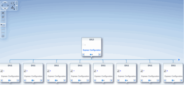
Description of "Figure 14-16 DS3 Connectivity in Capacity Tab"
Terminating and Enabling a Channelized Connectivity
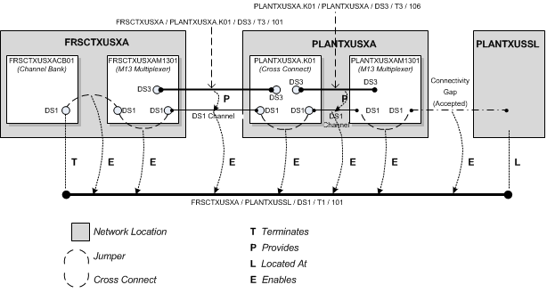
Figure 14-17 illustrates a channelized connectivity that is enabled by several different kinds of resources.
Figure 14-17 Enabled Channelized Connectivity
Description of "Figure 14-17 Enabled Channelized Connectivity"
In this example, the FRSCTXUSXA / PLANTXUSSL / DS1 / T1 / 101 facility is terminated on a device interface in a channel bank located at the network location FRSCTXUSXA. Seven segments are required to complete the end-to-end connectivity path:
-
A jumper interconnects a DS1 interface on the FRSCTXUSXACB001 channel bank to a DS1 interface on the drop side of the FRSCTXUSXAM1301 multiplexer. The jumper is trail-bound because it was created as part of the connectivity design.
-
A cross-connect interconnects the DS1 interface on the FRSCTXUSXAM1301 multiplexer to a DS1 interface provided by a DS3 interface on the line side of the same device. This cross-connect is interface-bound because it is considered to be manufactured into the device.
-
A DS1 channel provided by a DS3 channelized connectivity runs from the FRSCTXUSXAM1301 multiplexer to a DS1 interface (DS1-3) provided by a DS3 interface on the PLANTXUSXA.K01 digital cross-connect system. The PLANTXUSSL network location in this example identifies a service location where the DS1 facility is terminated on a customer-owned device.
-
A trail-bound cross-connect interconnects the DS1-3 interface to the DS1-14 interface provided by another DS3 interface on the opposite side of the PLANTXUSXA.K01 device.
-
A DS1 channel provided by the PLANTXUSXA.K01 / PLANTXUSXA / DS3 /T3 /106 facility connects the digital cross-connect to a DS1 interface provided by a D3 interface on the drop side of the PLANTXUSXAM1301 multiplexer.
-
An interface-bound cross-connect connects the drop-side interface to a line-side interface on the PLANTXUSXAM1301multiplexer.
-
An accepted connectivity gap runs from the PLANTXUSXAM1301 multiplexer to PLANTXUSSL. This segment is treated as an accepted connectivity gap because the customer-owned device and cable pairs running to it from the PLANTXUSXA location are not inventoried.
About Virtual Connectivity
UIM supports virtual connectivity and termination. You can create Channelized Connectivity entities with VC4, VC3, VC2, VC11, and VC12 rate codes.
A connectivity is considered virtual when it terminates on the sub-interfaces of the device interface on which its parent facility is terminated rather than on its own device interface.
For example, a VC4 facility is used to abstract out the optical physical transport of traffic between two points in an SDH network. A VC4 facility effectively delivers a 155 Mb connectivity. This connectivity can be configured to carry lower-order traffic within lower-order containers (C4, C3s, and C12s) to deliver E4, E3, and E1 services.
VC4 connectivities are used extensively in SDH networks to provide logical connectivity. A large part of SDH capacity planning is determining VC4 network location-to-location routes and monitoring the utilization levels of those routes. High utilization levels of the 63 lower-order (VC12) channels within VC4s is the main driver for deciding that a new VC4 path is required.
You can configure VC4 and VC3 connectivities to provide capacity at other levels. VC2, VC11 and VC12 connectivities have single-channel structures defined by the UIM signal architecture.
You can use gap analysis for VCn connectivities.
Note:
You cannot use a single channel of a facility to enable a connectivity when all three share the same rate code. For example, a VC4 channel provided by a VC4 facility cannot be used to enable another VC4 connectivity.
Virtual Termination
UIM supports the virtual termination of connectivities on device interfaces that already have channel terminations. Connectivities can be virtually terminated on the same device interfaces that already terminate its enabling channels. A connectivity that has a single default channel with the same rate code as its parent can be terminated on the same device interface that its parent is terminated on.
For example, virtual termination can be used when a DS1 facility rides a DS1 channel from a DS3 facility. (See Figure 14-18.) The DS1 facility is virtually terminated on the same DS1 interfaces used to terminate its enabling DS1 channel. A DS0 channel provided by the DS1 facility is automatically terminated on a sub-interface. The DS0 channel termination is required to create a cross-connect that is part of the enablement of a DS0 service trail.
Figure 14-18 Virtual Termination on a DS1 Facility
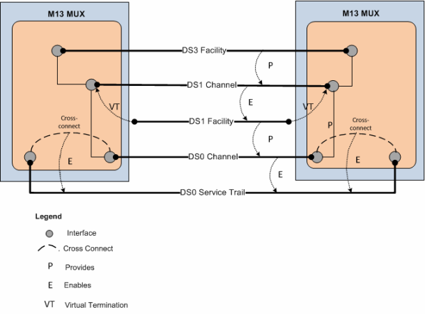
Description of "Figure 14-18 Virtual Termination on a DS1 Facility"
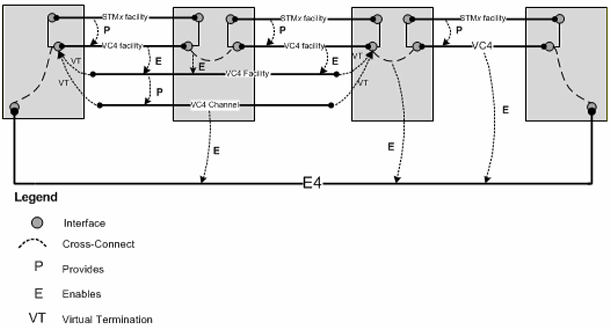
Figure 14-19 provides a simplified view of a STMx facility providing VC4 channels that enable a VC4 facility. The VC4 facility is virtually terminated on the same sub-interfaces that already terminate the enabling VC4 channels.
The VC4 facility is configured to have a single VC4 channel that enables an E4. Because this single channel has the same rate code as its parent facility, it is virtually terminated on the same sub-interfaces.
Figure 14-19 Virtual Termination on a VC4 Channel
Description of "Figure 14-19 Virtual Termination on a VC4 Channel"
Maintaining Channelized Connectivity and Network Resources
UIM provides features for optimizing network resource utilization by maintaining channelized connectivity and reconfiguring network topology:
-
You can groom a connectivity to change the riders that consume its channels. For example, in an OC3 facility, you can move a DS1 rider from one VT 1.5 channel to another within the facility or to a VT 1.5 channel in another facility.
-
You can rehome a channelized connectivity to change its termination. For example, you can move the termination of a DS3 facility from one device interface to another. The source and target device interfaces can be on the same device or on different devices, either at the same location or at different locations. Termination changes can result in changes to channel assignments, so a grooming activity can be required as the result of rehoming. See "About Rehoming" for more information.
-
In a network, you can insert a new node that represents a logical device into the middle of an edge that represents a channelized connectivity. UIM automatically creates new connectivities, manages the termination changes, and manages channel reassignments. See "Inserting and Removing Nodes in Networks" for more information.
-
In a network, you can remove a node that represents a logical device on which two connectivities are terminated. UIM changes terminations and reassigns riders to a connectivity that replaces the two that were previously terminated on the removed device. See "Inserting and Removing Nodes in Networks" for more information.
You plan and manage these maintenance activities as parts of projects. For example, you can define a project for all the grooming and rehoming activities related to a particular network infrastructure change. When you submit an activity in a project, UIM processes it in the background and returns the results. See "Projects" for more information.
Caution:
While an activity is being processed, you should avoid making changes to entities that might be modified by the activity. Changes could result in processing failure.
Project Activities Page Overview
You work on network maintenance activities in the Project Activities tab. The Project Activities tab includes a list in which you add and manage maintenance activities. When you select a maintenance activity in this list, you see a specialized area for that type of activity. For example, when you select a rehoming activity, you see a section in which you select a source logical device and a section in which you select the target logical device. After you have made these selections, you select a connectivity to rehome to the target.
After you have configured an activity, the Project Activities tab displays the specific actions that must be completed for the activity. Each change item includes an entity and the action that must be completed.
When you have finished configuring an activity, you can submit it for processing. You can submit activities one at a time or in groups. UIM processes activities in the background and reports its progress in the Percent Complete column in the Activities tab. When you submit multiple activities, UIM processes them sequentially.
The interval at which UIM refreshes the Percent Complete columns in the Activities tab and Change items tab is configurable. The default interval is 15 seconds. See UIM System Administration for information about setting the interval.
The Project Details page has a Project Activities tab that contains several activities in various statuses. A Rehome activity is selected, so Source and Target appear. The Change Items tab lists the connectivities affected by the rehoming and the actions that will be completed. The Impact Items tab is populated as the change items are processed.
About Change Items and Impact Items
When you configure an activity, UIM determines which entities must be changed as a direct result of the activity and what actions must be completed. The combination of an entity and an action is called a change item. The change items for an activity are displayed in the Change Items tab of the Project Details page when the activity is selected.
When you submit an activity, UIM processes its change items sequentially. During processing, UIM creates impact items, which are combinations of entities and actions that must be completed to make it possible to complete change items. Because impact items are not known until processing begins, they are displayed only after the activity is submitted. Impact items are displayed in the Impact Items tab as they are created.
Figure 14-20 shows the Change Items and Impact Items tabs for a grooming activity that reassigned a T1 facility from one channel of a T3 facility to another channel in the same facility. A connectivity gap results from this change, as shown in the Impact Items tab. The Parent Change Item column refers to the change item that generated the impact item.
In this case, UIM was able to resolve the gap successfully. If UIM could not resolve the gap, the action would be shown in In Progress status and you would need to resolve the gap manually.
Figure 14-20 Change Items and Impact Items Tabs

Description of "Figure 14-20 Change Items and Impact Items Tabs"
Table 14-2 lists all of the actions that can be taken on entities as part of change items and impact items.
Table 14-2 Activity Item Actions
| Activity Item Action | Description |
|---|---|
|
Groom |
Re-route traffic riding a connectivity. |
|
Rehome |
Change a connectivity design at an endpoint. |
|
Insert Node |
Insert a node that represents a logical device into a network |
|
Remove Node |
Remove a node that represents a logical device from a network. |
|
Insert Device |
Insert a logical device into a connectivity design. |
|
Remove Device |
Remove a logical device from a connectivity design. |
|
Replace Edge |
Replace one network edge with another network edge. |
|
Resolve Gap |
Fill a gap in a connectivity design by adding a channel assignment, cross connect, or jumper. |
|
View Design |
Viewing the connectivity design related to an Activity Item. |
|
Terminate |
Define the end point of the connectivity. For example, a connectivity can be terminated on a device interface. |
|
Unterminate |
Remove the end point of the connectivity, such as the device interface on which the connectivity is terminated. |
About Connectivity Design Versions and Grooming and Rehoming
When you groom or rehome a connectivity, a new connectivity design version is created in some cases:
-
If the connectivity design is completed before grooming or rehoming and there is no in-progress version, a new in-progress version is created. The changes required by the grooming or rehoming activity occur in this version. If no unresolved gaps result from the activity, the version is completed automatically. If unresolved gaps remain after the grooming or rehoming, the new version remains in In Progress status.
-
If the connectivity has an in-progress design version before grooming or rehoming, that version is used for the changes. This version is not completed automatically as part of the grooming or rehoming activity.
See "About Design Versions" for more information.
About Grooming
When you groom a connectivity, you change the assignments of its channels. For example, when you groom an OC3 facility, you can move a DS1 rider from one VT 1.5 channel to another within the same facility or to a VT 1.5 channel in another facility.
These design changes involve unassigning riders from one or more channel segments along with related gaps, jumpers, and cross-connects. Riders are then reassigned to new channels. Grooming does not involve changing connectivity termination (rehoming) except in the case of virtual termination.
Grooming often occurs because of network changes that make new routes available or make old routes inefficient. For example, if new devices are added to a network, an existing route may now have an unacceptable number of hops. Planning and management processes can discover these situations and recommend more efficient routing to be implemented by grooming.
Grooming is intra-facility when the new channel assignments are in the same bearer facility as the old channel assignments or inter-facility when the new channel assignments are in a different bearer facility from the old channel assignments.
Grooming can move a rider from one bearer to two bearers. For example, if you add device C between existing devices A and B, two new segments are created (A-C and C-B). You can groom a connectivity that was riding channels in the original A-B segment to ride channels in the newly created segments instead. (UIM can automatically perform this grooming activity when you insert new network nodes. See "Inserting and Removing Nodes in Networks" for more information.)
Grooming a virtual path connectivity can cause changes to virtual termination if the changes include the first or last segment in the design.
Before you groom a connectivity, you must ensure that the connectivities are properly designed and terminated and that the target connectivity has enough capacity to accommodate all riders that are reassigned to it.
Grooming Scenario: lnter-Facility
This scenario illustrates an inter-facility grooming activity in which two connectivities are re-assigned from channels in one facility to channels in another facility.
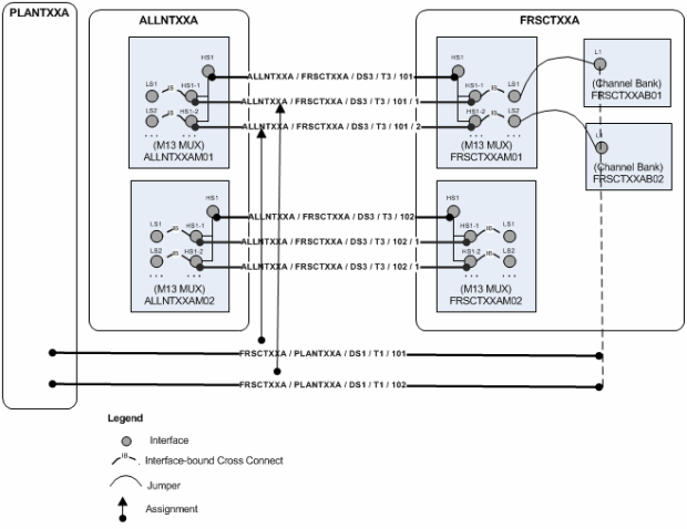
Figure 14-21 illustrates the scenario before grooming takes place. Two T1 connectivities (FRSCTXXA / PLANTXXA /DS1 / T1 /101 and FRSCTXXA / PLANTXXA /DS1 / T1 /102) are riding channels provided by the ALLNTXXA / FRSCXXA /DS3 / T3 /101 facility. To free capacity, the T3 facility is groomed to reassign the T1 connectivities to channels provided by a different facility (ALLNTXXA / FRSCXXA /DS3 / T3 /102). Note that the T1 facilities are enabled in part by cross-connects from the FRSCTXXAM01 MUX to channel banks at the same location.
Figure 14-21 Intra-Facility Grooming: Before
Description of "Figure 14-21 Intra-Facility Grooming: Before"
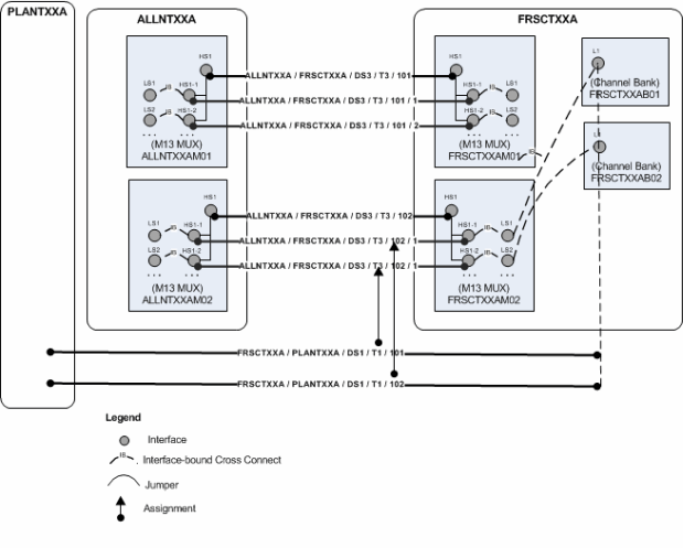
Figure 14-22 illustrates the results of the grooming activity. The channel reassignments have occurred. The new channels are terminated on a different MUX, so UIM has added cross-connects to join the interfaces on the MUX to the channel banks on which the T1s are terminated.
Figure 14-22 Inter-Facility Grooming: After
Description of "Figure 14-22 Inter-Facility Grooming: After"
Grooming Scenario: Intra-Facility Grooming for Ethernet Over SDH
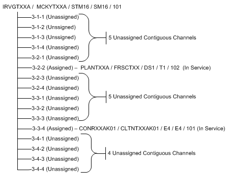
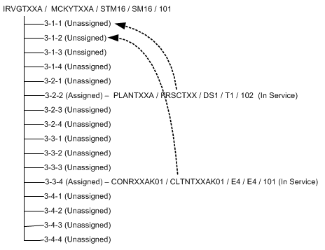
In this scenario, a new 1 Gbps Ethernet connection will be enabled by an existing SDH STM16 facility (represented in UIM as a channelized connectivity). This arrangement requires the use of 7 VC4 channels, each providing a bandwidth of 155.520 Mbps. To deliver the bandwidth, the channels must be concatenated virtually. This virtual concatenation scenario requires that the channels be contiguous in the SDH facility.The available capacity in the STM16 facility is more than the required 1 Gbps, but 7 contiguous VC4 channels are not available because of fragmentation. Figure 14-23 illustrates an STM16 facility in which two channels (6 and 12) are currently assigned. There are 14 unassigned channels, but only 5 contiguous channels are available.
Figure 14-23 Intra-Facility Grooming: Before
Description of "Figure 14-23 Intra-Facility Grooming: Before"
To free the required number of contiguous channels, the STM16 facility must be groomed. The channel assignments of the two E4 connectivities must be moved to make 7 contiguous channels available. The required changes are illustrated in Figure 14-24.
Figure 14-24 Intra-Facility Grooming: Required Changes
Description of "Figure 14-24 Intra-Facility Grooming: Required Changes"
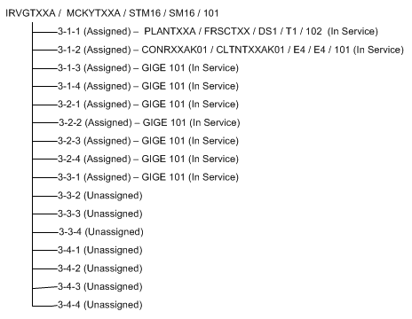
With these changes, a large contiguous block of channels becomes available, making it possible to assign them to the Ethernet pipe. Figure 14-25 illustrates these assignments.
Figure 14-25 Intra-Facility Grooming: After
Description of "Figure 14-25 Intra-Facility Grooming: After"
To reassign the two connectivities to different channels within the STM16, UIM must also reassign any cross-connects, jumpers, or gaps in the connectivity design.
Grooming Scenario: 2:2 Inter-Facility
You can groom multiple facilities simultaneously to reassign trails that are enabled by them. For example, a single service trail could be enabled by two separate connectivities along with cross-connects between interfaces that terminate them.
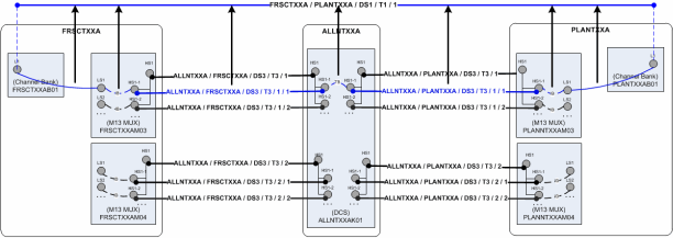
Figure 14-26 illustrates such a scenario. The FRSCTXXA/PLANTXXA/DS1/T1/1 connectivity is a service trail that is enabled by channels provided by the ALLNTXXA/FRSCTXXA/DS3/T3/1 and ALLNTXXA/PLANTXXA/DS3/T3/1 facilities. The existing multiplexers that terminate these facilities could be reaching their capacity, so you may need to groom the facilities to reassign their riders to channels on other facilities.
Figure 14-26 2:2 Inter-Facility Grooming: Before
Description of "Figure 14-26 2:2 Inter-Facility Grooming: Before"
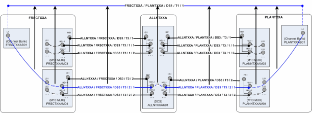
Figure 14-27 illustrates the situation after grooming has taken place. FRSCTXXA/PLANTXXA/DS1/T1/1 is now enabled by channels on other multiplexers at the same network locations and by interface-bound cross-connects between interfaces. UIM has automatically created a trail-bound interface between interfaces on the ALLNTXXK01 DCS. (The trail-bound cross-connect used to enable the trail previously has been removed.)
Figure 14-27 2:2 Inter-Facility Grooming: After
Description of "Figure 14-27 2:2 Inter-Facility Grooming: After"
To perform 2:2 (or n:n) grooming in UIM, you can select multiple facilities when you configure a grooming activity. See "About the Grooming User Interface" and the UIM Help for more information.
About the Grooming User Interface
You plan and manage grooming in the Activities tab of the Project Summary page. When you create or select a grooming activity, you see the Groom section. The Groom section allows you to select the source (the connectivity you are grooming) and the target (the connectivity to which you want to reassign channel riders).
After selecting the source and target connectivities, you use the Groom Connectivities Source and Target tree views to configure the grooming activity. You drill down through the source connectivity's channel hierarchy to select the channels whose riders will be reassigned. You then drill down through the channel hierarchy of the target connectivity to select the new enabling channels. You can select multiple channels to reassign in the same activity. Based on your selections, UIM populates the Proposed Changes table with a list of the entities that will be changed to complete the grooming activity.
When you have finished configuring the grooming activity, click Add to Groom. The Change Items tab in the Project Details page is populated with a list of entities that will change and the actions that will be taken on them. These change items correspond to the changes displayed in the Proposed Changes section in the Groom Connectivities dialog box.
Figure 14-28 shows the Change Items and Impact Items tabs for a grooming activity that reassigned a T1 facility from one channel of a T3 facility to another channel in the same facility. A connectivity gap results from this change, as shown in the Impact Items tab. In this case, UIM was able to resolve the gap successfully. If UIM could not resolve the gap, the action would be shown in In Progress status and you would need to resolve the gap manually.
Figure 14-28 Change Items and Impact Items Tabs

Description of "Figure 14-28 Change Items and Impact Items Tabs"
See "Projects" and the UIM Help for more information about managing projects and activities.
About Rehoming
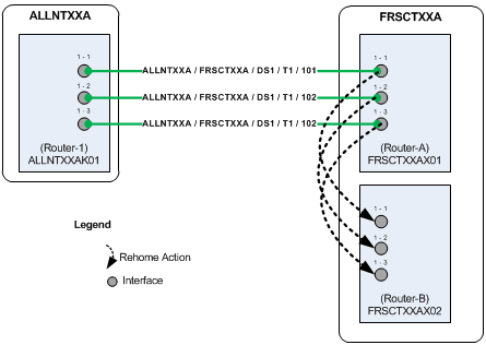
When you rehome a connectivity, you change one of its terminations. Rehoming may be required for load balancing or because of the removal or replacement of devices and interfaces. Figure 14-29 illustrates a simple scenario in which three T1 facilities are rehomed from interfaces on one router to interfaces on another router.
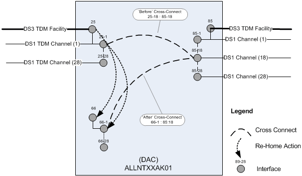
Rehoming a facility requires changes to the termination of the facility itself and to any channels it provides. Channels are re-terminated on sub-device interfaces provided by the new device interface on which the facility is terminated.
Figure 14-30 illustrates how rehoming a DS3 facility from one interface to another requires rehoming of its channels to sub-interfaces and therefore the creation of new cross-connects. For visual clarity, the illustration shows the impact on only one channel, but all 28 DS1 channels require rehoming and new cross-connects.
Figure 14-30 Rehoming Impact on Cross-Connects
Description of "Figure 14-30 Rehoming Impact on Cross-Connects"
Pipes and connectivities riding channels provided by the rehomed connectivity require design changes to reflect new interface and cross-connect assignments. To ensure date integrity in these situations, rehoming must occur recursively throughout the channel hierarchy of the channelized connectivity.
For example, when you rehome a DS3 facility, there are direct impacts to DS1 riders enabled by channels provided by the facility. If these riders are virtually terminated to the same DS1 sub-interfaces used by facility's DS1 channels, the DS1 riders must be rehomed to the new DS1 sub-interfaces. If the DS1 riders themselves provide channels that enable DS0 riders, the DS0 riders must also be rehomed.
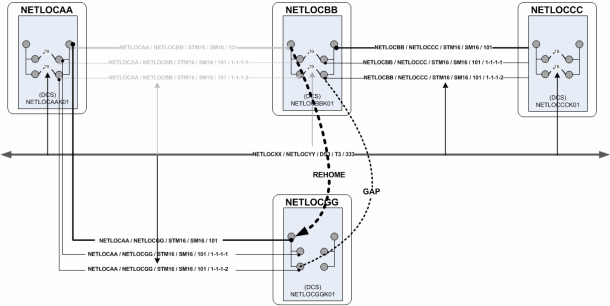
Rehoming can result in channel assignment changes that require a grooming activity. Figure 14-31 illustrates such a scenario. A DS3 facility (NETLOCXX / NETLOCYY / DS3 / T3 / 333) rides a channel provided by NETLOCAA / NETLOCBB / STM16 / SM16 / 101. The Z end point of this SM16 facility is being rehomed to a device in NETLOCGG. The DS3 facility must be reassigned to a different channel as a result of the rehoming.
Because connectivity identifiers include A and Z network/entity location codes, they can change when connectivities are rehomed. In Figure 14-31, the connectivity NETLOCAA / NETLOCBB / STM16 / SM16 / 101 changes to NETLOCAA / NETLOCGG / STM16 / SM16 / 101. See "About Connectivity Identifiers"for more information about how connectivity identifiers are constructed.
The serial number of a connectivity can also change as a result of rehoming. Connectivity serial numbers must be unique within the context of the A and Z location pairs, so rehoming can result in a conflict with an existing serial number.
The gray channels in Figure 14-31 indicate the assignments that are removed as the result of rehoming. The channel reassignment from the NETLOCAA / NETLOCBB / STM16 / SM16 / 101 / 1-1-1-1 channel to NETLOCAA / NETLOCGG / STM16 / SM16 / 101 / 1-1-1-1 occurs automatically because rehoming a parent facility also rehomes its channels.
The DS3 rider has a gap, however, between the device interfaces on NETLOCGG and the drop side on NETLOCBB. You must resolve this gap separately from the rehoming activity.
About the Rehoming User Interface
You plan and manage rehoming in the Rehome section that becomes available when you create or select a rehoming activity. The Rehome section includes device tree views in which you select the source device (the device that provides the interface on which the connectivity is currently terminated) and the target device (the device that provides the interface that you want to terminate the connectivity).
After selecting the source and target devices, you use the Rehome Connectivities tree views to configure the activity. You drill down through the source device's hierarchy to select specific the device interface on which the connectivity is terminated. You then drill down through the hierarchy of the target device to select the new device interface. You can select multiple pairs of interfaces in the same activity. Based on your selections, UIM populates the Proposed Changes table with a list of the entities that will be changed to complete the rehoming activity.
When you have finished configuring the activity, click Add to Rehome. The Change Items tab in the Project Details page is populated with a list of actions that corresponds to the proposed entity changes from the dialog box.
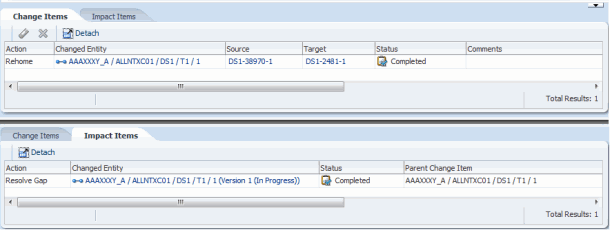
Figure 14-32 shows the Change Items and Impact Items tabs for a rehoming activity in which the end point of a T1 facility is moved from one device interface to another. A connectivity gap results from this change, as shown in the Impact Items tab. In this case, UIM was able to resolve the gap successfully. If UIM could not resolve the gap, the action would be shown in In Progress status and you would need to resolve the gap manually.
Figure 14-32 Rehoming Change Items and Impact Items Tabs
Description of "Figure 14-32 Rehoming Change Items and Impact Items Tabs"
See "Projects" and the UIM Help for more information about managing projects and activities.
Inserting and Removing Nodes in Networks
UIM enables you to insert and remove network nodes that represent logical devices. UIM manages the required actions, such as channel reassignments and creating connectivities.
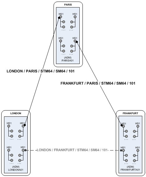
When you insert a node in this way, UIM creates two new connectivities to replace the existing connectivity. You select a logical device that the inserted node represents and specify the device interface on which two new connectivities will be terminated. Figure 14-33 illustrates a simple network scenario in which a new add-drop multiplexer in Paris is inserted between two existing multiplexers in London and Frankfurt. The previous London-to-Frankfurt STM16 connectivity is replaced by two new STM16 connectivities: one from London to Paris and another from Paris to Frankfurt.
Figure 14-33 Simple Node Insertion Scenario
Description of "Figure 14-33 Simple Node Insertion Scenario"
UIM automatically manages the channel reassignments and termination changes. For example, when you insert a node and replace a connectivity that has riders, the riders must be groomed to new channel assignments. UIM manages this grooming automatically.
Figure 14-34 and Figure 14-35 illustrate this scenario. In this example, the middle portion of a T1 facility's path rides a channel provided by the FRSCTXAA / PLANTXAA DS3 facility. The T1 rider has jumpers and cross-connects at its endpoints.
Figure 14-34 Network Node Insertion: Before

Description of "Figure 14-34 Network Node Insertion: Before"
A new device and location are inserted between the PLANTXXA and FRSXTXXA locations, resulting in the creation of two new T3 facilities to replace the previous T3.
The T1 rider must now be groomed to reflect the network changes. Its terminations on the channel banks are unchanged, but all of the jumpers, cross-connects, and channel assignments must be updated as shown in Figure 14-35.
Figure 14-35 Network Node Insertion: After

Description of "Figure 14-35 Network Node Insertion: After"
Connectivities that are assigned to the groomed T1 are unaffected because its terminations are unchanged. For example, if a DS0 service trail is riding a channel provided by the T1, its connectivity design requires no modification. It is still assigned to the same channel, although the parent facility of that channel has been groomed.
Removing a network is the reverse of inserting one. For example, suppose that you want to remove the node that represents logical device ALLNTXXAK01 in Figure 14-35. In this scenario, the two connectivities (and their channels) terminated on the devices must be unterminated and then replaced by a new connectivity that connects PLANTXXAM01 and FRSCTXXAM01. UIM handles the required termination changes and channel reassignments. Riders that were enabled by the existing connectivities are reassigned to the replacement.
You can insert a node into an edge:
-
When the edge represents only one connectivity.
-
The connectivity is represented by only one edge.
-
The connectivity is terminated by logical devices on both ends.
You can remove a node:
-
When the node has exactly two edges.
-
When all of the cross-connects in the device that the node represents are between the source connectivities represented by the source edges.
Node Insertion User Interface Overview
You manage node insertion in the Insert Node section that becomes available when you create or select an insert node activity. The section includes a network visualization in which you select the network that contains the affected nodes and edges.
You configure the activity in the Insert Node dialog box. This dialog box includes a wizard interface in which you:
-
Select the network edge into which you want to insert the node. The edge into which you insert the node must be a facility and not a rider.
-
Select the logical device you want the inserted node to represent. The device must have two free device interfaces that are compatible with the rate code of the existing connectivity represented by the edge.
-
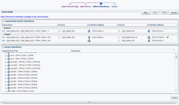
Select the device interfaces on which to terminate the two connectivities that will be created. The dialog box shows the existing connectivity (the source) and the new connectivities (the targets) in a table similar to the Connectivity Design tab used to enable and terminate channelized connectivity. You specify the device interfaces on which to terminate the Z end point of the first new connectivity and the A end point of the second. Figure 14-36 shows the Select Interfaces area of the dialog box. In this case, one device interface has been selected, as indicated by the green check mark. One device interface has yet to be selected, as indicated by the red icon.
Figure 14-36 Select Interfaces Area of the Insert Node Dialog Box
Description of "Figure 14-36 Select Interfaces Area of the Insert Node Dialog Box" -
Review proposed changes. The Review area of the dialog box provides a list of the selections you have made, as shown in Figure 14-37. You can use the Back button to navigate to previous areas if necessary.
Figure 14-37 Review Area of the Insert Node Dialog Box

Description of "Figure 14-37 Review Area of the Insert Node Dialog Box"
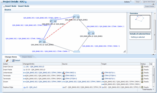
Figure 14-38 shows the Insert Node section after the activity has been configured. A new node representing the Q06_BANG.005.LD logical device will be inserted between the existing Q06_BANG.002.LD and Q06_BANG.003.LD nodes. The red dotted line represents the edge that will be replaced while the blue dotted line represents the two new edges.The Change Items tab shows the entities that will be changed as a result of the activity. Because the activity has not yet been submitted, the Impact Items tab has not been populated.
Figure 14-38 UIM Insert Node User Interface - After Activity Configuration
Description of "Figure 14-38 UIM Insert Node User Interface - After Activity Configuration"
After the activity has been processed, UIM saves the activity configuration details, change items, and impact items so that you can refer to them in the future. For example, you can view the network visualizations to see where the node was inserted.
Node Removal User Interface Overview
You manage node removal in the Remove Node section that becomes available when you create or select a remove node activity. The section includes a network visualization in which you select the network that contains the affected nodes and edges.
You configure the activity in the Remove Node dialog box. This dialog box includes a wizard interface in which you:
-
Select the network node that you want to remove.
-
Review proposed changes. You can use the Back button to navigate to previous areas if necessary.
When you have finished configuring the activity in the Remove Node dialog box, the network visualization in the Source area in the Remove Node section shows the planned changes with edges to be removed colored red.The Change Items tab is populated with a list of actions that corresponds to the proposed entity changes from the dialog box.
UIM saves the activity configuration details, change items, and impact items so that you can refer to them in the future. For example, you can view the network visualizations to see where the node was removed.
