15 Packet Connectivity
This chapter explains how you use packet connectivity features in Oracle Communications Unified Inventory Management (UIM). You can groom or rehome a packet connectivity that acts as a rider or bearer. The procedure of grooming and rehoming a packet connectivity is similar to that of a channelized connectivity. See "About Grooming" and "About Rehoming" for more information on grooming and rehoming.
Packet connectivity is one of several types of connectivity supported by UIM. See "Connectivity Overview" for information about features shared by all Connectivity entities.
UIM packet connectivity support includes Packet Connectivity entities and other entities that work together to model an entire service.
About Packet Connectivity
In packet-based connectivity, data is transmitted in blocks called packets or cells. Because capacity for these technologies is defined by volume or bandwidth rather than by channels or time-slots, packet connectivity is sometimes called bandwidth connectivity. Several technologies are based on packet connectivity, including Ethernet, Frame Relay, Asynchronous Transfer Mode (ATM), and Multiprotocol Label Switching (MPLS).
In UIM, you use Packet Connectivity entities to represent this type of connectivity. Packet Connectivity entities are based on Connectivity specifications in which the Connectivity Classification is set to Packet.
UIM supports all of these technologies and provides extensive support for Carrier Ethernet in the OracleComms_UIM_CarrierEthernet cartridge. Support for other packet technologies is provided in the OracleComms_UIM_Packet cartridge. See UIM Carrier Ethernet Cartridge Guide and UIM Cartridge Guide for more information about the content of these cartridges.
Packet connectivity can coexist with channelized connectivity and pipes. For example, a packet facility can be enabled by one or more channels of a T-Carrier channelized connectivity. Similarly, a packet connectivity can enable or be enabled by a pipe.
UIM cartridges supply a number of Packet Connectivity specifications that you can use or modify. For example, the Carrier Ethernet sample cartridge includes specifications for ENNI, INNI, and UNI connectivities. The Packet sample cartridge includes specifications for ATM, Frame Relay, and other connectivities. You can also create your own packet connectivities in Design Studio. See Design Studio Help for more information.
About Flow Identifiers
Packet connectivity technologies use IDs or tags to differentiate network traffic and make it visible to only the appropriate devices. By isolating network traffic in this way, the same physical or infrastructure network can support multiple virtual networks. For example, the Carrier Ethernet technology uses VLAN IDs for this purpose. ATM uses VPI and VCI, while Frame Relay uses DLCI.
In UIM, you use Flow Identifier entities to represent these various types of identifiers. Flow identifiers are specification-based entities that can be customized to fit your business and technological requirements.
The Carrier Ethernet and Packet cartridges include Flow Identifier specifications. The Carrier Ethernet cartridge includes CE-VLAN, Custom-Tag, P-Tag, SP-VLAN, and W-Tag specifications. The Packet sample cartridge includes VCI, VPI, and DLCI specifications. You can use these specifications as they are or copy and modify them for your requirements. You can also create your own Flow Identifier specifications in Design Studio.
Flow identifiers can be marked as managed or unmanaged in their specifications:
-
Managed flow identifiers are grouped into network address domains and resource pools from which they can be selected and assigned to packet virtual networks (PVNs) and service networks. For example, the SP-VLAN flow identifier in the Carrier Ethernet cartridge is managed. See "Network Address Domains" and "About Inventory Group Types and Resource Pools" for more information.
-
Unmanaged flow identifiers are received on a service order and referenced with a service location on the service. They are provided by customers and therefore not managed by service providers. For example, the CE-VLAN flow identifier in the Carrier Ethernet cartridge is unmanaged.
In UIM, you can assign flow identifiers to packet virtual network configurations and service network configurations. When you assign a flow identifier to a network, UIM automatically assigns the flow identifier to all the flow interfaces in the network. You can assign flow identifiers to networks either in the Network Topology view or in the network configuration.
You can manually unassign and assign flow identifiers for individual flow interfaces. For example, you may want to implement VLAN ID translation. See "VLAN ID Translation" for more information.
Assigning Flow Identifiers to Connectivities and Connectivity Segments
You can assign flow identifiers to connectivities while you are designing them. There are two options:
-
You can assign a flow identifier to the connectivity and have that flow identifier referenced on both the A and Z flow interfaces terminating the connectivity.
-
You can assign a flow identifier to the connectivity and have that flow identifier referenced by either the A or Z flow interface.
You can also assign flow identifiers to the individual segments of a connectivity design. The flow identifier is assigned to the parent connectivity, and is automatically referenced on the flow interface configuration of the flow interfaces on each end of the connectivity segment. The flow identifier is then displayed on the connectivity design.
See UIM Help for more information about assigning flow identifiers to connectivities.
Q-in-Q Stacking
UIM flow identifiers support Q-in-Q stacking. Q-in-Q stacking enables VLAN IDs to be encapsulated (stacked) within each other. Stacking allows traffic from different service providers with the same VLAN ID to travel safely through a network.
For example, suppose Customer A's CE- VLAN and Customer B's CE-VLAN use the VLAN ID 10. When the traffic enters the service provider network, Customer A's traffic can be stacked on the service provider's SP-VLAN ID 50 and Customer B's traffic can be stacked on the service provider's SP-VLAN ID 100. This stacking enables the two customer's traffic to be separated within the network even though their original VLAN IDs are the same.
In UIM, you implement Q-in-Q stacking by defining stacking levels in Flow Identifier specifications. For example, the Carrier Ethernet sample cartridge includes a CE-VLAN Flow Identifier specification with a stacking level of 0 and an SP-VLAN Flow Identifier specification with a stacking level of 1. That means that flow identifiers based on the CE-VLAN specification can be stacked within flow identifiers based on the SP-VLAN specification. To implement Q-in-Q stacking with these specifications, you include a CE-VLAN flow identifier in the Service configuration and add the SP-VLAN flow identifier to the PVN.
See Design Studio Help for more information about designing Flow Identifier specifications.
VLAN ID Translation
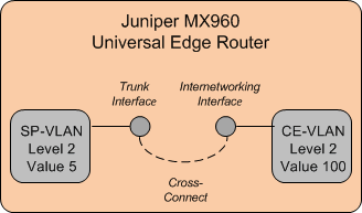
In Carrier Ethernet networks, VLAN ID translation is sometimes required. VLAN ID translation involves changing the ID of incoming packets at a switch. For example, Figure 15-1 illustrates a situation in which an interface on a switch carries traffic from one direction with VLAN ID 5 and another interface on the same switch carries traffic from the other direction with VLAN ID 100. The switch receives traffic on one interface, translates the ID, and then sends the traffic out on the other interface.
To model VLAN ID translation in UIM, you manually assign flow identifiers to flow interfaces, thereby overriding the flow identifier assignment from the PVN. You assign the flow identifier from the Network Topology view of the PVN in which the flow interface appears.
For example, in the example in Figure 15-1, you can model the switch as a logical device. The logical device has two flow interfaces with a cross-connect between them. To translate the VLAN ID, you assign an SP-VLAN flow identifier with stacking level 2 and an ID of 5 to one interface and a P-Tag flow identifier with stacking level 100 and an ID of 100 to the other.
A flow interface can have multiple flow identifiers. For example, an Ethernet flow interface could have a CE-VLAN flow identifier that identifies traffic coming from a customer's service location. The same flow interface can have an SP-VLAN flow identifier that identifies a PVN, such as an EVC.
Performance Parameters
Services based on packet connectivity often include requirements for class of service (CoS) and quality of service (QoS). These requirements guarantee specific levels of performance to the subscriber. For example, when a subscriber contracts with a service provider for Carrier Ethernet service, the service provider guarantees bandwidth and excess bandwidth levels based on performance parameters.
In UIM, these performance parameters are modeled as Custom Object entities with characteristics that represent the various metrics.
For example, the Carrier Ethernet cartridge includes a number of Custom Object specifications that model the CoS and QoS attributes defined by the Metro Ethernet Forum (MEF). Specifications for other entities, such as service and network configurations, include references to the CoS and QoS Custom Object specifications that apply to them.
Similarly, the Packet Cartridge includes specifications for ATM and Frame Relay QoS and traffic parameters.
You can also define your own Custom Object specifications for QoS and CoS requirements not supplied in the cartridges.
See "Custom Objects" for more information about Custom Object entities and UIM Carrier Ethernet Cartridge Guide for more information about how they are used in Carrier Ethernet services.
Enabling Packet Connectivity
Like other connectivities, you enable and terminate a packet connectivity as part of the design process. Packet connectivity can be enabled by channelized connectivity, packet connectivity, and pipes in any combination.
See "Designing Connectivity" for more information about the connectivity design process, including using gap analysis.
Enabling Packet Connectivity with Channelized Connectivity
Enablement by channelized connectivity includes support for virtual concatenation (VCAT), a system in which a subset of channels in a channelized facility are grouped to enable packet connectivity.
Without VCAT, bandwidth is wasted because a full facility is used to support “non-telephony" bit rates. For example, Carrier Ethernet includes a 10 Mbps bit rate. Without VCAT. a full E3 facility (34.468 Mbps) or DS3 facility (44.736 Mbps) is required to enable the Carrier Ethernet connectivity.
With VCAT, that 10 Mbps connectivity can be enabled by two of the four E2 channels in an E3 facility or seven of the 28 DS1 channels in a DS3 facility. The unused channels can be used for other purposes.
The UIM signal architecture determines which channels can be virtually concatenated to support which packet connectivities. The valid VCAT combinations are reflected in the Connectivities Supported By list in the Gap Analysis page.
When you select a channel arrangement in the Connectivities Supported By list and select the Contiguous Channels, gap analysis includes those criteria in its search.
Enabling Packet Connectivity with Packet Connectivity
You can enable a packet connectivity with one or more packet connectivities. (This capability is called “packet-over-packet.") For each segment of the path, the rate code of the enabling connectivity must be greater than or equal to than the rate code of the enabled connectivity. For example, an Ethernet connectivity with a 10GigE rate code can be enabled by a connectivity with a 40GigE rate code but not by one with a 1GigE rate code.
Some special termination rules apply in packet-over-packet enablement scenarios. See "Packet-Over-Packet Termination Rules" for more information.
Packet-Over-Packet Termination Rules
Packet connectivities enabled by other packet connectivities must be terminated on flow interfaces. This rule is true throughout all levels of enablement. For example, your inventory could include a 40GigE connectivity enabling a 10GigE which enables a 1GigE connectivity. In this situation, 10GigE and 1GigE connectivities must be terminated on flow interfaces. Assuming it is not enabled by another packet connectivity, the 40GigE connectivity can be terminated on either a flow interface or directly on a media interface.
For packet connectivities not enabled by other packet connectivity, you can terminate directly on a media interface only if its rate code exactly matches the rate code of the connectivity. If the rate codes, do not match, you see an error message.
If the rate code of the media interface exceeds that of the connectivity, UIM creates a child flow interface that matches the capacity of the connectivity. It then terminates the connectivity on that flow interface. The remaining capacity of the parent media interface remains available for consumption. You must select the Terminate at Flow Interface menu option for flow interfaces to be created by UIM. Otherwise, you see an error message stating that the device interface rate code does not support the connectivity.
In the Connectivity Design tab, you select how you want to terminate a connectivity. If you select Terminate at Media Interface, you can select a media interface. If you select Terminate at Flow Interface, you select a media interface and UIM automatically creates a flow interface for you.
In most cases, flow interfaces that UIM creates are deleted when they are unassigned or when a connectivity design that includes them is cancelled. There are some exceptions to this rule. For example, if you cancel the second version of a connectivity design, only flow interfaces created in the second version are deleted. Flow interfaces included in the first version remain. Similarly, if in a connectivity design you unassign or delete segments that include flow interfaces, those flow interfaces are restored if you cancel the design.
Packet Enablement Scenarios
The following sections provides three examples of terminating and enabling a packet connectivity. Two of the scenarios include VCAT.
Ethernet Packet Connectivity Enabled by Ethernet Packet Connectivity
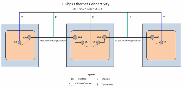
In this scenario, you want to create a 1 Gbps Ethernet connectivity between Tucson, AZ to Tucumcari, NM. As shown in Figure 15-2, your network already includes locations in all three cities.
40 Gbps connectivity exists between Tucson and Albuquerque and Albuquerque and Tucumcari, represented in UIM as ALBQ/TUCS/40GigE/GE40/1 and ALBQ/TUCU/40GigE/GE40/1. These two connectivities are terminated on media interfaces of logical devices located at the three network locations shown in Figure 15-2.
You will enable the new 1 Gbps connectivity with capacity from the two 40 Gbps connectivities.
You start by creating the 1 Gbps Ethernet connectivity, specifying Tucson as the A location and Tucumcari as the Z location. The connectivity will have a name similar to TUCS / TUCU / 1GigE / GE1 / 1.
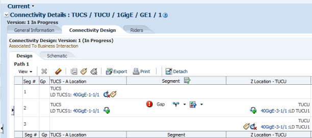
When the TUCS / TUCU / 1GigE / GE1 / 1 connectivity has been created, open its Connectivity Design tab to terminate and enable it:
-
On the A side of TUCS / TUCU / 1GigE / GE1 / 1, click the Terminate icon, then select Terminate at Flow Interface. When the Device Search screen appears, select a media interface on the device that terminates the ALBQ/TUCS/40GigE/GE40/1 connectivity, then click Assign.
UIM creates a 1 Gbps flow interface under the media interface and assigns it to the TUCS / TUCU / 1GigE / GE1 / 1 connectivity.
-
Repeat step 1 for the Z side, selecting the mediate interface that terminates ALBQ/TUCU/40GigE/GE40/1
The connectivity is now terminated. You now must resolve the gap.
-
At the Gap icon, select Assign Connectivity to Resolve this Gap, search for the ALBQ/TUCS/40GigE/GE40/1 connectivity, and click Assign.
UIM does the following:
-
Creates a flow interface under the 40GigE media interface so that the cross connect can be created.
-
Creates a trail bound cross-connect to the 40GigE media interface of the 40GigE connectivity.
-
Adds the1GigE connectivity as a rider of the ALBQ/TUCS/40GigE/GE40/1 connectivity and consumes the relevant capacity.
A new gap appears, this time for the segment between ALBQ and TUCU.
-
-
At the newly created Gap icon, repeat step 3, searching for the ALBQ/TUCU/40GigE/GE40/1 connectivity.
UIM does the following:
-
Creates two flow interfaces: one under the 40GigE media interface on the Z side of the ALBQ/TUCS/40GigE/GE40/1 connectivity and another under the 40GigE media interface on the A side of the ALBQ/TUCU/40GigE/GE40/1 connectivity.
-
Creates a cross connect between the two new flow interfaces.
-
Creates flow interface under the 40GigE media interface on the Z side of the ALBQ/TUCU/40GigE/GE40/1 connectivity.
-
Creates a trail-bound cross-connect from the 40GigE media interface on the Z side of ALBQ/TUCU/40GigE/GE40/1 connectivity to the 1GigE Flow Interface terminating the TUCS / TUCU / 1GigE / GE1 / 1 connectivity.
You can partially automate this process by using Gap Analysis to replace steps 3 and 4. Specify Tucson and Tucumcari as the source and target. See "Assigning Transport" and UIM Help for more information.
-
-
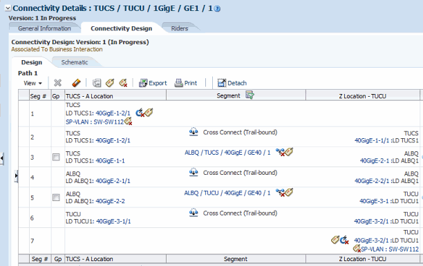
Assign a flow identifier to UCS / TUCU / 1GigE / GE1 / 1.
In this example, you assign a flow identifier to the connectivity you are designing and apply it to both flow interfaces. You could also choose to assign a flow identifier to the connectivity and apply it to only one flow interface. In addition, you could choose to assign flow identifiers to the connectivity segments in the design. See "Assigning Flow Identifiers to Connectivities and Connectivity Segments" for more information.
-
In the tool bar, click the Assign Flow Identifier to Both Ends icon.
The Flow Identifier Search page appears.
-
Search for and select a flow identifier.
The selected flow identifier is assigned to the connectivity and referenced by the flow interfaces that terminate it.
-
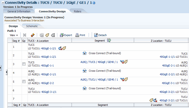
Figure 15-3 illustrates the completed design.
Figure 15-3 1 Gbps Ethernet Connectivity Enablement
Description of "Figure 15-3 1 Gbps Ethernet Connectivity Enablement"
Figure 15-4 illustrates the enablement scenario schematically.
Figure 15-4 1 Gbps Ethernet Connectivity Enablement (Schematic View)
Description of "Figure 15-4 1 Gbps Ethernet Connectivity Enablement (Schematic View)"
UNI Connectivity Enabled by T-Carrier Channels
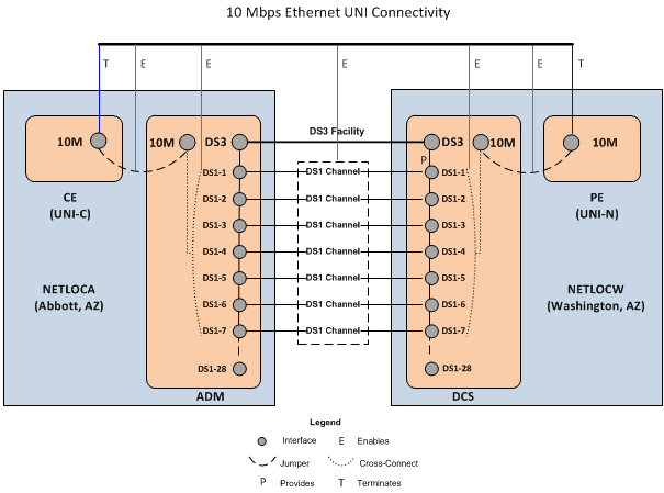
This section provides an example of Ethernet UNI connectivity enabled by virtually concatenated channels in a T-Carrier facility. The example assumes that you are a Carrier Ethernet service provider implementing a solution over your own network infrastructure. No other service providers are involved and you have installed CPE at the customer site.
The service location on the A side of the UNI connectivity is in Abbot, AZ. Because you have installed network equipment at this site, you can model it as both a service location and a network location (NETLOCA). The PE router on the Z side of the connectivity is at your network location in Washington, AZ (NETLOCW).
Transport is provided by seven channels from a DS3 facility that connects the two network locations. The channels use VCAT to combine their bandwidth. A jumper connects a 10 Mbps interface on the CE device to a 10 Mbps interface on the add-drop multiplexer (ADM) that also provides interfaces for the DS3 facility and its channels. A similar arrangement of cross-connects and a jumper connect the DCS and PE on the other end of the connectivity. Figure 15-5 illustrates this enablement scenario.
Figure 15-5 Ethernet UNI Connectivity Enabled by DS1 Channels
Description of "Figure 15-5 Ethernet UNI Connectivity Enabled by DS1 Channels"
Assuming that the DS3 facility already exists, has had its capacity configured, and has seven contiguous, unassigned channels, do the following to create and design the UNI connectivity:
-
Create two logical devices based on the Packet Network Device specification to represent the CPE and the PE.
-
Locate the CPE device at the service location in Abbott, AZ.
-
Locate the PE device at the NETLOCW network location.
-
Create one or more device interfaces with a 10M (10 Mbps) rate code on each device.
-
-
Create a connectivity based on the UNI Connectivity specification.
-
Specify the A side of the connectivity as the combined network and service location in Abbott, AZ.
-
Specify the Z side of the connectivity as NETLOCW.
-
Set the rate code to 10M (10 Mbps).
-
-
In the Connectivity Design tab of the new connectivity, terminate the connectivity on 10M device interfaces on the CPE and PE devices.
-
Select the central segment of the path and perform a gap analysis. (See UIM Help and "Assigning Transport" for more information about gap analysis.)
-
Specify NETLOCA and NETLOCW as the Source and Target locations.
-
In the Connectivities Supported By area, select (7) DS1 and Contiguous Channels.
UIM returns a path that includes seven channels in the preexisting DS3 facility. (Other paths may also be returned depending on the resources in your network.)
-
-
Assign the path that includes the DS3 facility to the segment.
-
Resolve the remaining gaps by creating jumpers on the A and Z sides of the connectivity.
-
Complete the connectivity design.
INNI Connectivity Enabled by SDH Channels
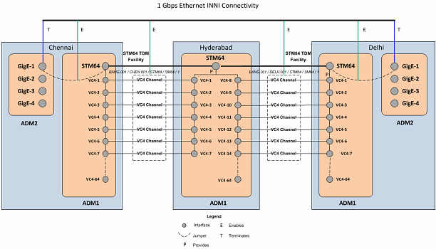
This section provides an example of the creation and design of a 1 Gbps Ethernet INNI connectivity that is enabled by seven virtually concatenated VC4 channels provided by an STM64 channelized connectivity. The example assumes that you are an Ethernet service provider and that no other service providers are involved in the solution.
An Ethernet INNI connectivity between Chennai and Delhi is enabled by two segments of an SDH ring network that also connects Bangalore and Hyderabad. Figure 15-6 illustrates the enablement scenario.
Figure 15-6 Gigabit Ethernet Enabled by VC4 Channels
Description of "Figure 15-6 Gigabit Ethernet Enabled by VC4 Channels"
SDH Network Infrastructure
In this example, an existing SDH ring network connects offices in Bangalore, Hyderabad, Delhi, and Chennai. These customer sites are represent in UIM by four property locations:
-
BANG
-
HYDB
-
DELH
-
CHEN
There are add-drop multiplexers (ADMs) at each location, represented in UIM by Logical Device entities with the following network entity codes:
-
HYDB.001.ADMLD
-
BANG.001.ADMLD
-
DELH.001.ADMLD
-
CHEN.001.ADMLD
Each ADM includes a device interface hierarchy that includes two STM64 interfaces, each with 64 VC4 sub-interfaces.
Connectivity in the ring network is represented by 4 STM64 Channelized Connectivity entities:
-
BANG.001 / CHEN.001 / STM64 / SM64 / 1
-
CHEN.001 / HYDB.001 / STM64 / SM64 / 1
-
HYDB.001 / DELH.001 / STM64 / SM64 / 1
-
BANG.001 / DELH.001 / STM64 / SM64 / 1
The connectivities are terminated on the STM64 interfaces at the property locations. The capacity of each connectivity is configured to 64 VC4 channels, corresponding to the 64 VC4 sub-interfaces on each media interface.
Creating and Designing the INNI Connectivity
To represent ADMs for the INNI connectivity, create two Logical Device entities based on the Packet Network Device specification located at the existing property locations for Chennai and Delhi. Name these logical devices DELH.002.ADMLD and CHEN.002.ADMLD. On each logical device, add 4 GigE device interfaces.
Create a Connectivity entity with the following attributes:
-
Technology: Ethernet
-
Specification: Ethernet INNI Connectivity
-
A Network Location: CHEN.002
-
Z Network Location: DELH.002
-
Rate Code: GigE
-
Function: GE1
-
Duplex Mode: Full Duplex
-
MTU Size: 1522
-
Physical Medium: 10BASE-T
In the Connectivity Design tab for the Ethernet INNI connectivity, complete the design as follows:
-
Terminate the A side of the connectivity on a GigE interface of the CHEN.002.ADMLD logical device.
-
Terminate the Z side of the connectivity on a GigE interface of the DELH.002.ADMLD logical device.
-
Use gap analysis with the following details and update the channels:
Source: CHEN.001
Target: DELH.001
Connectivities Supported By: 7VC4
Contiguous Channels: True
Gap analysis finds the STM64 connectivities from CHEN.001 to BANG.001 and from BANG.001 to DELH.001 and assigns seven VC4 channels to the INNI connectivity.
-
Resolve the remaining gaps by creating jumpers on the A and Z sides of the connectivity.
-
Complete the connectivity design.
