11.3 Configuring an ECM Workflow
This section describes how to configure an ECM Workflow.
The following is a sample workflow (AML) used to demonstrate how to configure the workflows in the ECM using PMF.
Creating Workflow
To create a workflow, follow these steps:
- Navigate to the Process Modeller window under Processing Modelling
Framework.
Figure 11-4 Process Modeller Window
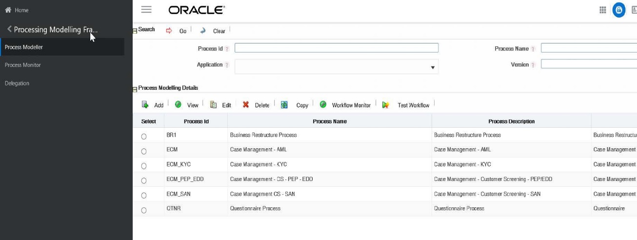
- Go to the Process Modelling Details section. Click Add. The Process
Details window is displayed.
Figure 11-5 Process Details
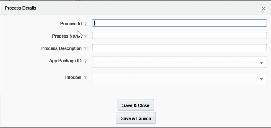
- Enter the following details in the Process Details window:
Table 11-3 Process Details
Field Name Description Process Name Enter the Process name for ECM workflow. Process Description Enter a brief description of the Process. App Package ID Select the Case Management from the App Package ID drop-down list. Infodom Select the ECMINFO from the Infodom drop-down list. This is the default Infodom. You can configure your own Infodom. It is the information domain in which you want to create the business process. Process ID Enter the new ECM workflow Process ID. - Click Save & Close to save the definition and go back to the Process
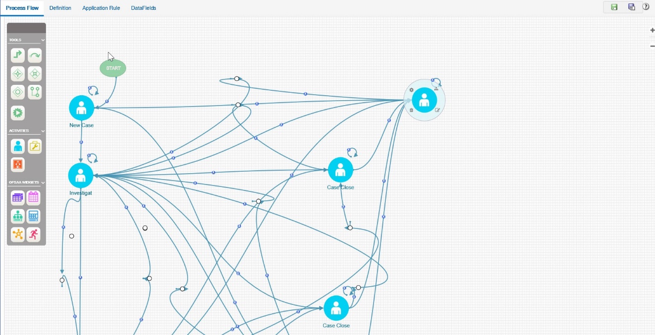
Modeller Summary window or Save & Launch to save the definition and
open the Process Modeller Editor window.
Figure 11-6 Process Modeller Editor window
Defining Datafields
Data Fields are Process variables which hold the data information required to be passed between ECM and Process Engine.
Data Field which is also known as Process Variable helps Processes to access and store information from outside the application. Often the process flow is based on the value of this information. In other cases,this information is the result of running the tasks in the process. This tab helps to view, add, edit, and delete Data Fields associated with the Process.
The defined Data field is populated and used when you are defining a new Application Rule (Stored Procedure, Function, Java External API). It is used in the Input Parameter field. For more information, see the section Defining Application Rules.
For more information on Data fields, see the Processing Modelling Framework section of Oracle Financial Services Analytical Applications Infrastructure User Guide.
Defining Application Rules
Application Rules is the interface through which Process Engine executes the Application Business Logic and other Conditional logic. This tab helps to add, edit, and delete Application Rules associated with the Process.
The Application or API Rule is the interface between the process engine and the application, including any parameters to be passed.
- Execution Rule: These are Business Logic executed as Task by an Activity.
- Decision Rule: This rule returns the Boolean value “True/False”, used in decision making during split/branching of transition.
- Selection Rule: This rule fetches some value, useful to get value dynamically from a table or other source.
For example:
select v_created_by from fct_expenses where id=101
Following are the supported Application Rule Types:
- SQL, JAVA
- Stored Procedure
- Function
- Java External API
- Web services
- Outcome Rules
- Expression
- Attribute Expressions
Formore information, see the Processing Modelling Framework section of Oracle Financial Services Analytical Applications Infrastructure User Guide.
Using Process Modeller Editor
Using the Process Modeller Editor window you can perform the following tasks:
- Adding Transition
- Adding an Activity
- Adding Transition
Starting a Process
Using this component you can start a new ECM workflow.
To start a process, follow these steps:
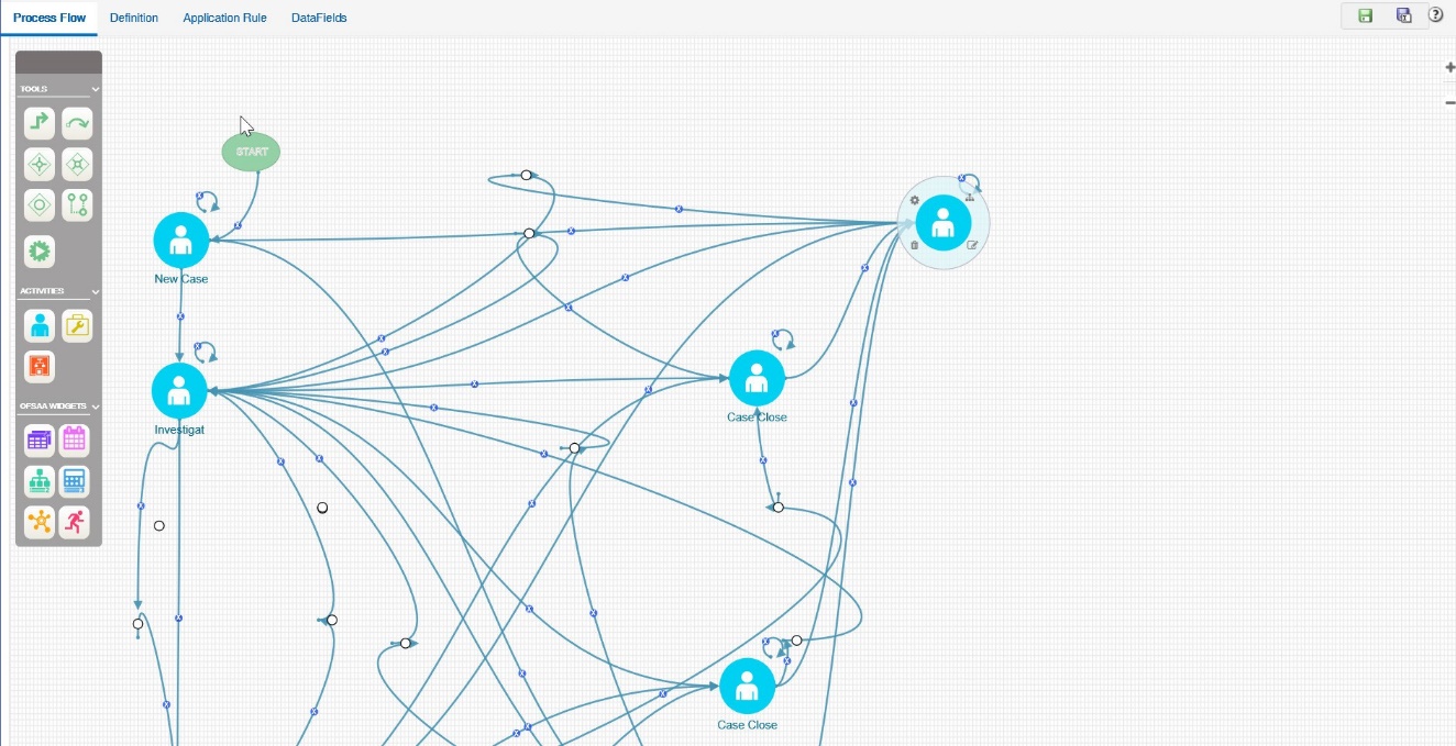
- Navigate to the Process Flow tab, click Startfrom the toolbar and then click the canvas where you want to draw the activity. The new Start icon is displayed. This Start activity indicates the first activity to be executed in the Process.
- Double-click the Start icon.
Figure 11-7 Starting Process
- Enter the following information in the respective fields:
Table 11-4 Process
Field Name Description Activity ID Displays the automatically generated Activity ID. Activity Name The activity name is displayed automatically the same as the Activity ID. Modify the activity name if required. Activity Desc Enter the description of the Activity. Activity Type By default, the activity type of the selected activity is displayed.
To change the activity type, select the required activity type from the drop-down list. The options are Manual, Automatic, Start, Parallel, Sequential, Connector, Run Task, Multi-choice, and sub-process.
Status Select the status of the activity from the drop-down list. For example, Closed-SAR, New, Investigation.
This is not applicable if the Activity is a Run Task.
Outcomes Select the required Outcomes from the drop-down list. For example, Approve, Reject, or, Submit.
This is not applicable if the Activity is a Service Task or Run Task.
File Upload Click Attachment and browse to select the file you want to upload. The progress of file upload is shown. The following message is displayed: Your file has been uploaded after the successful upload of the file.
Only a single file can be uploaded. If you upload a new file, the existing file is replaced with the new one. Click the Attachment icon adjacent to the file name to remove the file.
If a file is attached, the Attachment icon is displayed. Click the Attachment icon to view or save the file.
This section explains how to implement the newly created process.
Adding TransitionThis section explains how to add the transition to the newly created process.
Adding an ActivityTo add an activity, follow these steps:
- Click an activity under the Activities toolbar in the left panel and then click the canvas where you wantto draw the activity. The options are Human Task, Service Task, Run Task, and Sub Process.
- Double-click the icon. On the Right Panel, the Activity tab is displayed.
- Enter the following information in the respective fields:
Table 11-5 Adding Activity
| Field Name | Description |
|---|---|
| Activity ID | Displays the automatically generated Activity ID. For example, Job_1504159648899. |
| Activity Name | The activity name is displayed automatically the same as the Activity ID. Modify the activity name if required. For example, New Case. |
| Activity Desc | Enter the description of the Activity. |
| Activity Type |
By default, the activity type of the selected activity is displayed. Select the activity type as Manual from the drop-down list. To change the activity type, you can select the required activity type from the drop-down list. The options are Manual, Automatic, Start, Parallel, Sequential, Connector, Run Task, MultiChoice, and sub-process. |
| Status | Select the status of the activity from the drop-down list as New. The list displays the seeded values in the AAI_WF_STATUS_B table. |
| Outcomes |
Select the required Outcomes from the drop-down list. Thelist displays the seeded values in the AAI_WF_OUTCOMES_B table. This is not applicable if the Activity is a Service Task or Run Task |
Figure 11-8 Adding Activity
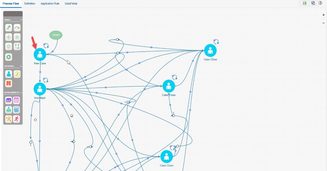
This section explains how to implement the New Case as an activity.
To implement the newly created activity, follow these steps:
- Select the Implementation tab. The Implementation details are
displayed.
Figure 11-9 Implementation Details
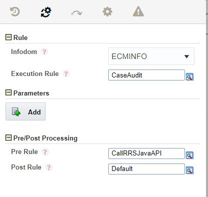
- Go to the Rule section. Select ECMINFO as the information domain from the Infodom drop-down list.
- Selec tthe execution rule which must be executed for this activity. For example, Case Audit. Or, you can search for the execution rules using the Searchicon.
- For Run Task: Click Search. The Run Component Details window is displayed. Expand Base Run or Simulation Run and select the required Run definition from the Segment. Click OK.
Using this component you can add the transition to New Case.
To add a transition, follow these steps:
- Go to the Process Flow tab, click Transition from Tools.
- Click the activity from which you want to start the transition.
- Again, click the activity to which you want to connect the transition.
- Double-click the Transition and enter the required details in the
Edit Transition window.
Or Double-click the Activity for which you want to add a transition. On the Right panel, click the Transitions icon and click Add. The Add New Transition window is displayed.
Figure 11-10 Add Transition
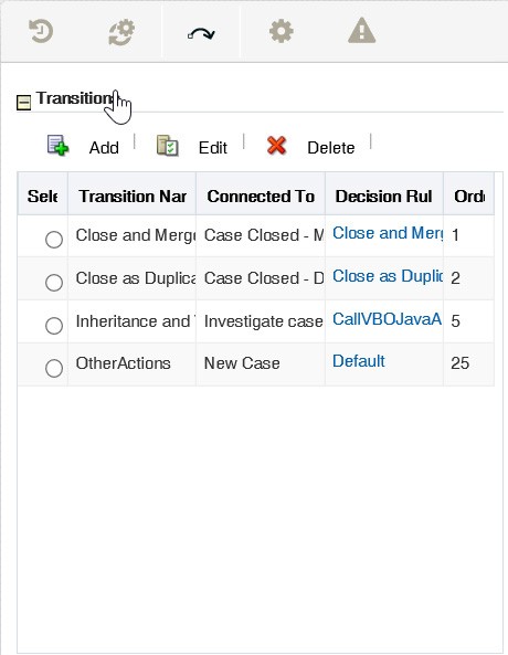
- Enter the following information in the respective fields:
Table 11-6 Transition
Field Name Description Transition Name Enter the Transition Name. For example, 404688668_Job_1495627226471 Connected To Select the activity (as New Case) to which you want to connect the current activity, from the Connected To drop-down list. All defined activities in the current Business Process are displayed. Decision Rule Select the appropriate Decision Rule by clicking the Search icon. This rule is validated during Process execution. If the output value is TRUE which indicatesSuccess, the process has to flow through this transition to go to the next activity. If the output value is FALSE which indicates Failure, the current transition is ignored and the next transition is taken for evaluation if available. If all the transition rules fail (that is evaluated to value FALSE), then the Process remains in the current State.
For more information, see the Defining Application section.
Order Enter the Precedence value based on which the transition Decision rules must be executed for multiple transitions, in the Order field. This affects transitions from a Sequential gateway only. - Click OK. The transition has linked two activities. That is
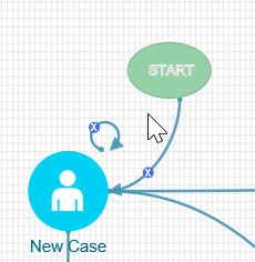
Start and New Case.
Figure 11-11 Adding Transition
