- User Guide
- Modeling
- Graphs
- Accessing the Graph Summary Page
- Create an Edge
Create an Edge
An Edge can be used to connect two different nodes or connect to itself. When
compared to nodes, edges also capture the basic information like name, description,
attributes to an edge, and possible pipelines that can be attached to an edge.
Figure 8-106 Edge

To create an edge, perform these steps:
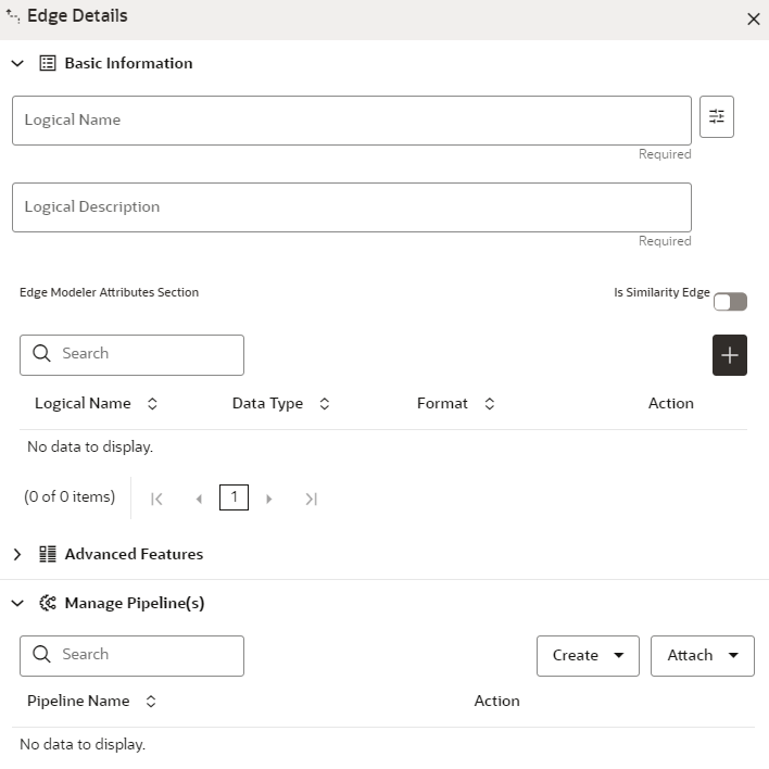
- Hover on the Node to create a relationship between them. The Edge Detailsscreen is displayed.
Figure 8-107 Edge Details

- In the Logical Name field, enter the Node's name or
click the Setting icon.The Setting pop-up window is displayed.
Figure 8-108 Setting

- Select the required edge from the options displayed and choose the required color for the edge using the Select Color option.
- Click OK. The selected edge is displayed on the graph pipeline.
- To add attributes to the edge, click the Add
icon.
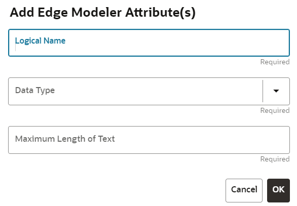
Figure 8-109 Add Edge Modeler Attribute(s) screen
 The Add Edge Modeler Attribute(s) screen is displayed.
 - In the Logical Name field, enter the logical name for
the edge attribute. This field is mandatory.
- In the Data Type drop-down, select the data type based
on your requirements. The available data types are Text, Number, and Date. This field is mandatory.Based on the data type selection, the following input field is displayed.For example, the Maximum Length of Text field is displayed if the data type is selected as Text.
- Enter the data and click Ok. The edge attribute is displayed on the Edge Details page.
Figure 8-110 Search
 By clicking on the Add icon, you can add any number of edge attributes based on your requirements.OR
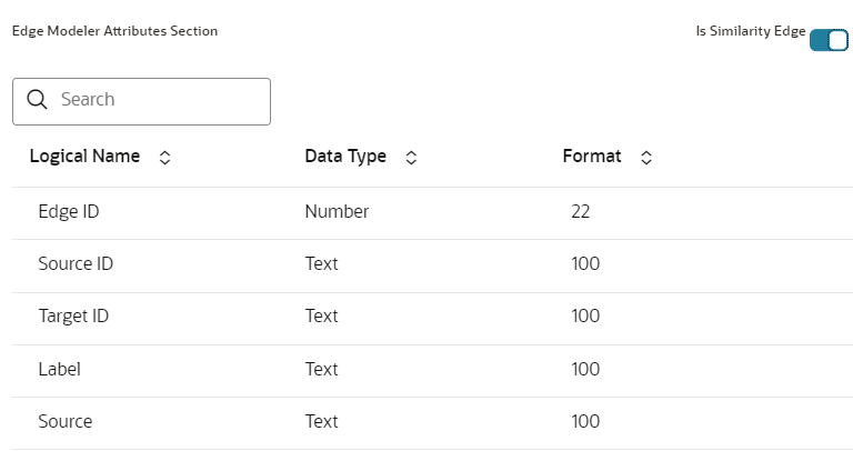
Figure 8-111 Edge Details
 Click the Is Similarity Edge toggle button the Edge Modeler Attributes section to add the pre-defined set of attributes available in the edge.Similarity Edgesin the graph are created by Match Rules. If the edge is defined using Match Rule (under Manage Pipeline, by selecting Match Rule from drop down), the toggle button should be enabled to make it a Similarity Edge.
 - Under the Advanced Features group, you can specify the
Edge Retention Policy. For example, An Edge Retention Policy of 7 Days specifies that the current edge would be retained in the physicalized Graph for a period of 7 Days.
- Enter the retention count and select the retention duration from the
drop-down.The available retention durations are Days, Weeks, and Months.
Figure 8-112 Retention Durations tab

- Enable the Pluggable Attribute, then the corresponding
drop-down will contain the list of attributes of the Edge. Pluggable edges are those edges whose data can be directly plugged in to the graph. In Financial Crime and Compliance domain, Transaction is a pluggable edge, which is generally large and is difficult to find out difference/ delta between two subsequent loads. Hence, it’s data is provided for a range of dates which can be directly plugged in to the PGX memory while refreshing the graph.Any pluggable edge should have an identifier attribute, which is of “Date” data type. Figure: Pluggable Attribute.
Figure 8-113 Pluggable Attribute

- Under the Key Attributes field, select the Column,
Start, and End identifier from the respective Identifier drop-down. Without
these attributes, an edge cannot be created. All the created edge attributes are displayed under this drop-down.
Figure 8-114 Key Attributes

- Under the Manage Pipeline(s) group, you can either
create a new data pipeline if the edge is coming from source data and Match
Rules, if a similarity edge is to be created between nodes or attach the
existing pipeline and Match Rules.
Figure 8-115 Manage Pipeline(s) for Edge

- Click Create drop-down and then select the Data
Pipeline. The Create Pipeline window is displayed.
Figure 8-116 Create Pipeline

- Select the Create New Data Pipeline option and then
click OK. The Pipeline Designer page is displayed.
- To create a data pipeline, see the Creating a New Data
Pipeline section.
OR
- To clone from an existing data pipeline, see the Cloning from an Existing Data Pipeline section.
Note:
Define persist of the Data pipeline of the corresponding edge with the prescript. See the Prescript Condition section for more details. - To create a data pipeline, see the Creating a New Data
Pipeline section.
- Click Create drop-down and then select the
Match Rules from the Manage Pipeline(s) group.The Create Pipeline window is displayed.
Figure 8-117 Create Pipeline

- Select the Create New Match Rule option and then click
Ok. The Create Match Ruleset window is displayed
- To create a Match Rule, see the Creating Match Ruleset
section.
OR
- To clone from an existing match rule, see the Cloning Ruleset (Match) section.
Note:
The newly created data pipeline and match rule are not automatically added to the edge. You must attach using the Attach drop-down option.By clicking on the Attach drop-down, you can add any number of data pipelines/match rules to the Node-based on your requirements.The selected data pipeline/match rule is displayed.Figure 8-118 Create Pipeline

- To create a Match Rule, see the Creating Match Ruleset
section.
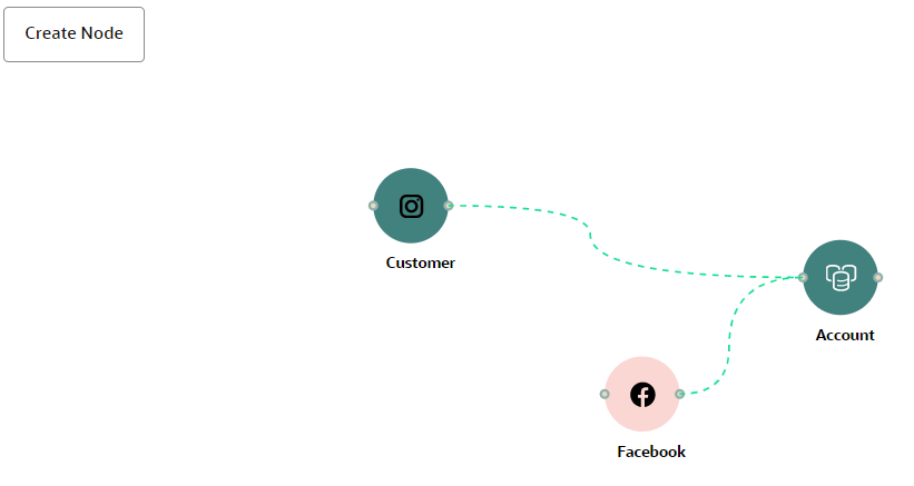
- Click OK.An Edge is created between the Customer, Facebook, and Account as shown in the below example.
Figure 8-119 Graph page
