Note:
- This tutorial requires access to Oracle Cloud. To sign up for a free account, see Get started with Oracle Cloud Infrastructure Free Tier.
- It uses example values for Oracle Cloud Infrastructure credentials, tenancy, and compartments. When completing your lab, substitute these values with ones specific to your cloud environment.
Install and configure VMware Horizon on Oracle Cloud VMware Solution
Introduction
This tutorial provides an operational overview of how to install and configure VMware Horizon 8.x hosted on the Oracle Cloud VMware Solution software-defined data center (SDDC) cluster. The focus of this tutorial is to highlight the ‘how-to’ steps required for Oracle Cloud Infrastructure (OCI) and the prerequisites to deploy VMware Horizon. The intent is to enable Oracle Cloud VMware Solution teams and customers to perform these deployment tasks in a proof-of-concept (POC) mode. VMware Horizon on Oracle Cloud VMware Solution is considered a ‘TechPreview’ while a joint Reference Architecture is being developed.
Since this is an Oracle public cloud deployment, the Oracle Cloud VMware Solution steps in OCI include virtual local area network (VLAN) setup, Load Balancer as a service (LBaaS), Database as a service (DBaaS), SDDC cluster deployment, route rules, security lists, and so on, which are unique to this deployment model. Once these infrastructure steps are completed along with the prerequisites within the cloud, the actual VMware Horizon steps remain unmodified as Horizon steps have no variances. Hence, the emphasis of this tutorial is more on the Oracle Cloud steps and their associated prerequisites. We used vSphere 7.0 deployment for this tutorial; however, relevant steps for vSphere 6.7 are also covered.
Technical Overview
Oracle Cloud VMware Solution is a customer-managed solution, where you can build and configure VMware vSphere clusters on OCI bare-metal shapes with Layer 2 (L2) virtual networking. Prior to deploying Horizon, you need to build the Oracle Cloud VMware Solution cluster (with three nodes minimum for virtual storage area network [VSAN]) along with the prerequisites highlighted throughout this tutorial.
For the purpose of this VMware Horizon ‘how-to’ operational guide, the following high-level reference architecture is proposed.
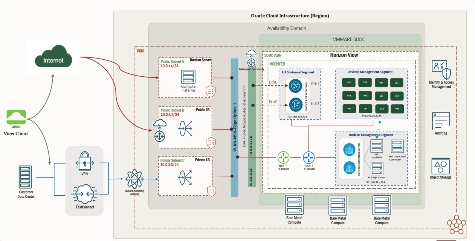
The VMware Horizon on Oracle Cloud VMware Solution architecture is divided into two parts:
- Deployment Model 1: If you are required to access connection servers and the virtual desktop infrastructure (VDI) environment only from an internal network and you do not expect public access, you can simply ignore the following sections:
- Add a New VLAN for UAG Appliances (vSphere 6.7 and 7.0)
- Deploy and Configure a UAG
- Deploy and Configure a Public Load Balancer
- Deployment Model 2: If you are required to access the environment from a public access point, complete the entire tutorial.
Configure the Oracle Cloud VMware Solution SDDC Cluster
This tutorial assumes that you have access to the Oracle Cloud VMware Solution console with appropriate identity and access management (IAM) roles to deploy Oracle Cloud VMware Solution in their compartment. You can also refer to their Oracle Cloud Infrastructure (OCI) tenancy limits, quotas and usage to check the ESXi/SDDC limits prior to deploying the clusters.
Deploy and Access the Oracle Cloud VMware Solution Cluster
To deploy and configure a three-node Oracle Cloud VMware Solution cluster, you must have necessary credits to deploy the cluster.
-
Select your tenancy and log in to Oracle Cloud Console at https://cloud.oracle.com.
-
Select the appropriate region where you want the SDDC to be deployed.
Note:
- Refer to Deploy the SDDC to the Cloud and Create and configure an Oracle Cloud VMware Solution for a detailed step-by-step guide on deploying the Oracle Cloud VMware Solution SDDC.
- Once the deployment tasks for the cluster are completed, select the same region.
-
To access the credentials, select the region where the SDDC was installed and select the compartment.
-
From the navigation menu in the top-left corner, select Hybrid, select VMware Solution, and then select Software Defined Data Center.
-
Click the SDDC link that appears in the center pane (with an Active status). In this scenario, the SDDC is named SDDC.
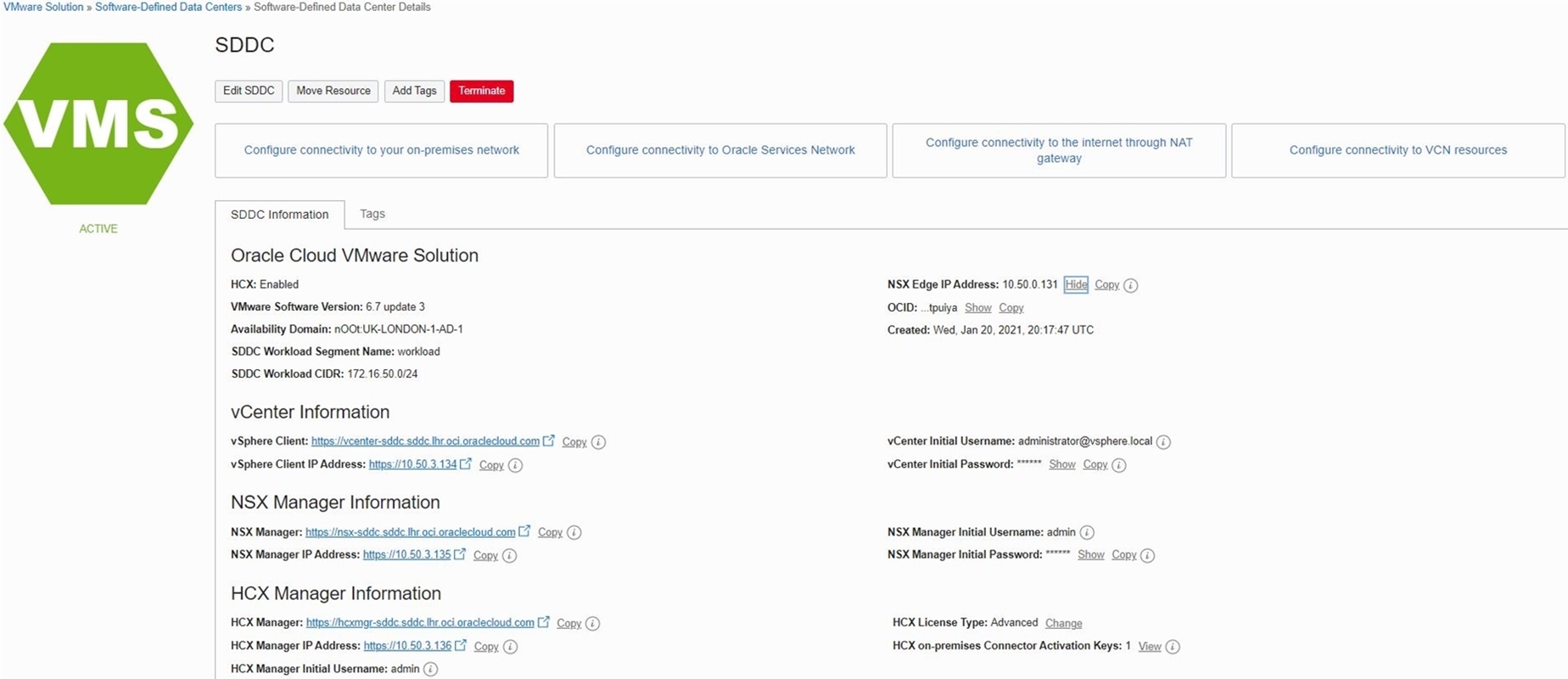
Note:
- Note the IP address for vCenter and NSX Manager and the vCenter credentials to access the environment.
- If a bastion host is required, use Bastion Hosts to securely deploy and configure a bastion.
Set up VMware Horizon on Oracle Cloud VMware Solution
This section describes prerequisites for setting up VMware Horizon 8.1 in your Oracle Cloud VMware Solution environment. For network communication TCP/User Datagram Protocol (UDP) port requirements for the Horizon components, see VMware Horizon ports and network connectivity requirements.
Prerequisites
- Event database platform of your choice (from the following list of supported VMware Horizon databases). This how-to guide validated with Microsoft SQL Server for event database. You can chose your own preferred database from the supported platform.
- Microsoft SQL Server
- Oracle Database
- PostgreSQL Database
- NSX Overlay segments for workloads in SDDC:
- Horizon Management segment: This network will host all Horizon management components:
- Connection servers
- Microsoft Active Directory Domain Controller for local authentication and DNS for name resolution
- Microsoft SQL Server
- Desktop Management segment: This network will host all VDI desktops
- UAG (Unified Access Gateway)Internal segment: This network will host UAG appliances second interface. Note that UAG appliances will be deployed with two interfaces, one from VLAN for external access and one from NSX-T overlay for internal communication and for performance scaling.
- Horizon Management segment: This network will host all Horizon management components:
- Active Directory Domain controller:
- For the purposes of this tutorial, the details of setting up Active Directory are not covered.
- Install and configure a Microsoft Certificate Authority (CA) role for connection server certificate renewal. The details of setting up the CA server are not covered in this tutorial.
- VLAN for UAG appliances. A dedicated VLAN is required to host UAG appliances for external public access.
- VDI ready Windows 10 template for desktop pools (optional):
- Desktop images must be tweaked to avoid any performance issues such as “Metro Apps” must be cleaned and Sysprep ran for optimizations
- Guest customization configuration to auto join desktop to domain controller post provisioning
- VMware OS optimization tool to optimize the guest operating system
- Virtual Network Computing (VCN) public subnet for Oracle Cloud Infrastructure (OCI) public load balancer for UAG appliances.
- VCN private subnet for the OCI private load balancer for the connection servers.
- VCN public subnet for the bastion host for the public access point to the OCI environment.
- VCN private subnet for Oracle Database (optional) if you decide to use Oracle Database for event database.
- Internet gateway for UAG appliances public access.
- Public Flexible Load Balancer (LBaaS) for the UAG appliance.
- Private Flexible Load Balancer (LBaaS) for connection servers.
- VM.Standard.X.X for the bastion host.
Version Details
| Component name | Validated against |
|---|---|
| VMware Horizon | 8.1.0 build - 17351278 |
| Unified Access Gateway | V20.12 (Non-FIPS) |
| VMware vSphere | 6.7 & 7.0 |
| VMware NSX-T | 2.5 & 3.0 |
| Database | Microsoft SQL Server 2019 |
| Windows VDI Template | windows 10 |
| Bastion Host | Windows Server 2016 Standard |
Set up Horizon Networking in SDDC
Prepare NSX for Horizon
The steps in this section are applicable to NSX-T 2.5 and 3.0.
-
Access the Horizon SDDC (as listed earlier in this tutorial) to obtain the login information for the NSX-T and VCenter.
- From the Oracle Cloud, select Hybrid, then select VMware Solution – Software-Defined-Data Centers (SDDC).
- Select the SDDC and view the SDDC Information section for the VCenter and NSX Manager login credentials.
- In this section, you can find the IP address and login credentials for VCenter and NSX. Use the login credentials to login using a web browser that has access to SDDC.
-
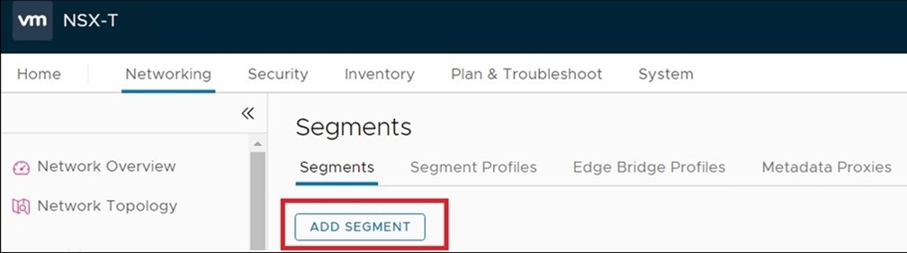
Log in to the NSX-T Manager dashboard.
-
From the NSX-T Manager, select Networking, click Segments and then click ADD SEGMENT.
-
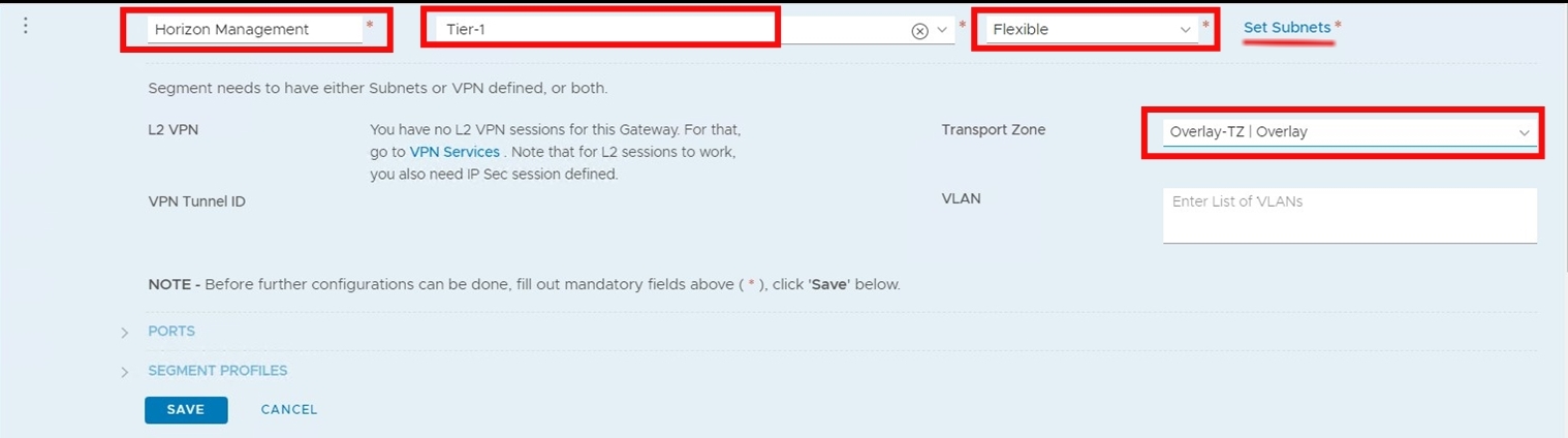
Create three segments one for Horizon management, one to host Desktops and one for UAG appliance internal traffic. Make sure these segments are connected to Tier1 Gateway. Define non-overlapping RFC1918 subnets to avoid any conflicts and ensure connectivity between the virtual machines (VMs).
Note: The ‘*’ indicates required fields. Select the overlay as the transport zone and ensure the status is Success. If you see a failed status for the segments, you may need to refer to the overlay connectivity and transport zone for further troubleshooting. Depending upon your NSX-T, follow the relevant steps.
Create a Network Segment in NSX-T 2.5
-
Click ADD SEGMENT and provide the details as shown in the following screenshot.
-
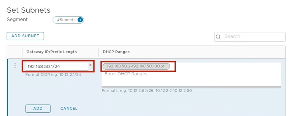
On the same screen, click Set Subnets, define the overlay subnet Classless Inter-Domain Routing (CIDR) and dynamic host configuration protocol (DHCP) range for the subnet. Refer to the following example screenshot.
Create a Network Segment in NSX-T 3.0
-
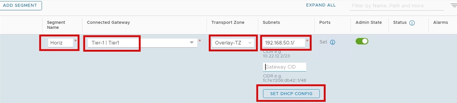
Click ADD SEGMENT and provide the details as shown in the following screenshot.
-
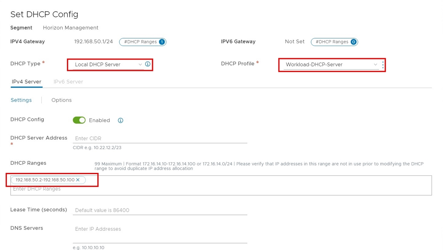
Click Set DHCP Config. Define the DHCP configuration as shown in the following screenshot.
-
Perform steps 1 to 2 for all three segments: Horizon Management, UAG Internal, and Desktop Management.
Note: If you are following Deployment Mondel 1, do not create UAG Internal.
-
Verify the segments are created and have a Success status and the Admin State is Up.

Note:
- The status of these new segments should be Successful and they can now be used.
- As a result of the previous step, you should now see three networks created in the SDDC vCenter server.
-
Navigate to the NSX-T Manager dashboard, Networking Services and then NAT to add required NAT rules.
-
Create Source Network Address Translation (SNAT) and NO_SNAT rules for newly created segments to establish the communication between VCN CIDR and to have internet access overlay segments.
Add SNAT and NO_SNAT rules in NSX-T 2.5
-
Log in to NSX Manager and navigate to the Advanced Networking & Security tab. Under Networking, click NAT.
-
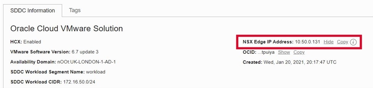
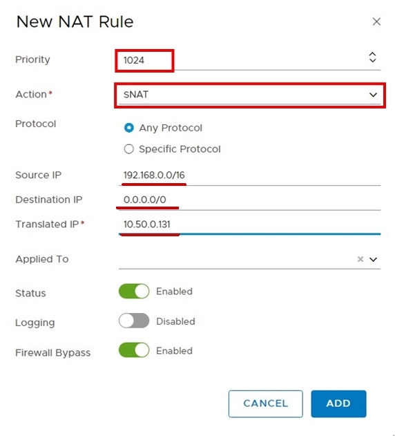
Select T0 as the logical router and click ADD to add the rule. Make sure to select the appropriate priority. The translated IP from the following screenshot is an IP address of NSX Edge Uplink 1 VIP. To find the IP address, log in to Oracle Cloud Console and navigate to the SDDC console summary page.
Note: It is advisable to add one time entry for the entire /16 subnet to avoid a single entry for all the individual segments. However, it is not mandatory and based on the design you can always add required Network Address Translation (NAT) and SNAT rules. The example in the following screenshot shows the entry for the entire /16 subnet, which covers all three overlay segments.
-
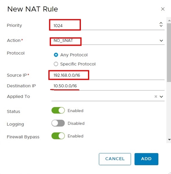
Add the NO_SNAT rule now. On the same screen, click ADD. Refer to the following screenshot to see the sample rule.
Note: The source IP is an overlay segment CIDR and the destination IP is OCI VCN CIDR. In this example, 10.50.0.0/16 is a VCN CIDR. Make sure to select the appropriate priority for proper execution.
You have to repeat the SNAT and NO_SNAT rules for all three overlay segments if /16 is not your desired design approach.
Add SNAT and NO_SNAT rules in NSX-T 3.0
There are no changes to how we add SNAT & NO_SNAT rules in the NSX-T 3.0 environment. However, there is a small change in the GUI.
-
Log in to NSX Manager, navigate to the Networking tab and select NAT under Network Services. Select T0 for the logical router.
-
Complete steps 1 to 3 from the Add SNAT and NO_SNAT rules in NSX-T 2.5 section.
-
Verify all the newly created rules for the overlay segment.
Add a New VLAN for UAG Appliances (vSphere 6.7 and 7.0)
First, we will create a network security group and route table for the new UAG VLAN.
Note: The steps in this section are applicable to both vSphere 6.7 and 7.0 environments.
-
Log in to the Oracle Cloud Console and from the navigation menu, select Networking, select Virtual Cloud Networks, select Network Security Group and click Create Network Security Group. Make sure that you are at the right compartment and the region where the VCN is deployed for the SDDC.
-
Provide the name of the network security group and click Next. Add security rules as shown in the following screenshot.
-
Log in to Oracle Cloud Console and from the navigation menu, select Networking, select Virtual Cloud Networks, select Internet Gateways and then click Create Internet Gateway. Follow the wizard and create an internet gateway.
-
Create a route table for new UAG VLAN. Log in to Oracle Cloud Console and from the navigation menu, select Networking, select Virtual Cloud Networks and then click Route Tables. Click Create Route Table.
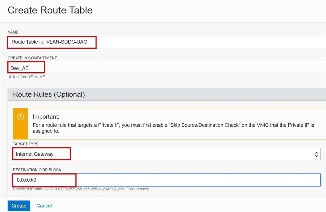
-
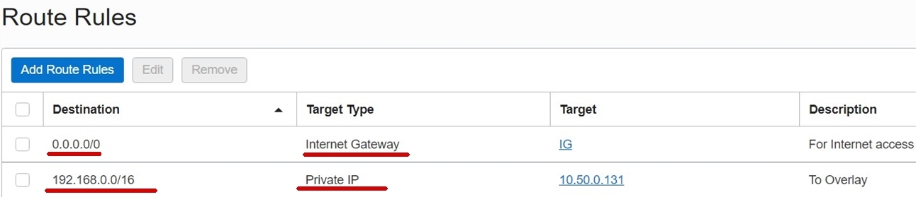
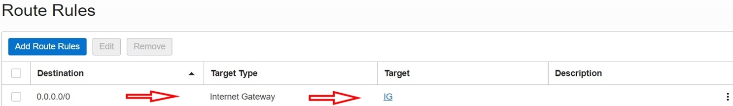
Under Route Rules, click Add Route Rules and select Internet Gateway as the target type with 0.0.0.0/0 as the destination CIDR block. Refer to the previous screenshot to see the Create Route Table page for UAG VLAN.
-
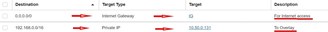
Update the route table created in step 5 to add a route to the overlay segments destination with Private IP to NSX Edge VIP as the Target Type. The resulting route table should be the same as in the following screenshot. In the screenshot, 10.50.0.131 is the NSX Edge IP address.
-
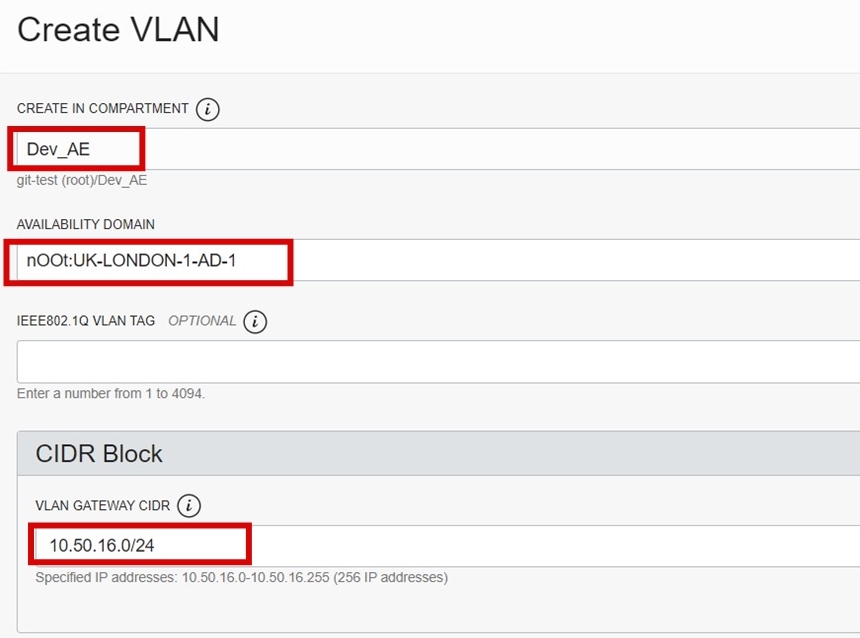
To create a VLAN for UAG, log in to the Oracle Cloud Console and navigate to Networking. Select Virtual Cloud Networks, select (SDDC VCN), and then select VLAN. Make sure you are at the right region and the compartment where the SDDC is deployed.
-
Click Create VLAN.
-
Specify the CIDR within VCN range and select the Availability Domain where the SDDC is deployed.
-
On the same screen, select the network security group that you created in step 2 and the route table you created in step 4.
Now, let’s add this newly created VLAN for all ESXi hosts that are a part of the SDDC cluster.
Attach VLAN to an SDDC Cluster in vSphere 6.7
-
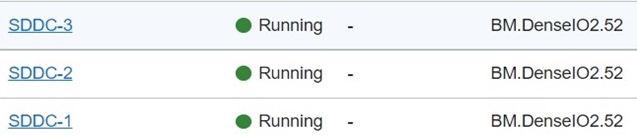
From the Oracle Cloud Console, click the navigation menu, select Compute Instances, and then select ESXi Node (repeat on all applicable ESXi Bare metal nodes in the Oracle Cloud VMware Solution cluster).
-
In the Compute section, click one of the ESXi hosts, in this example it’s SDDC-1.
-
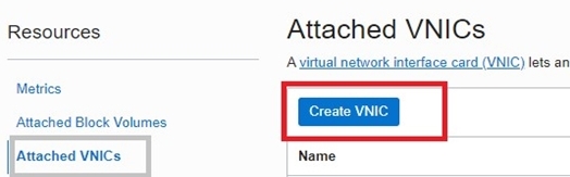
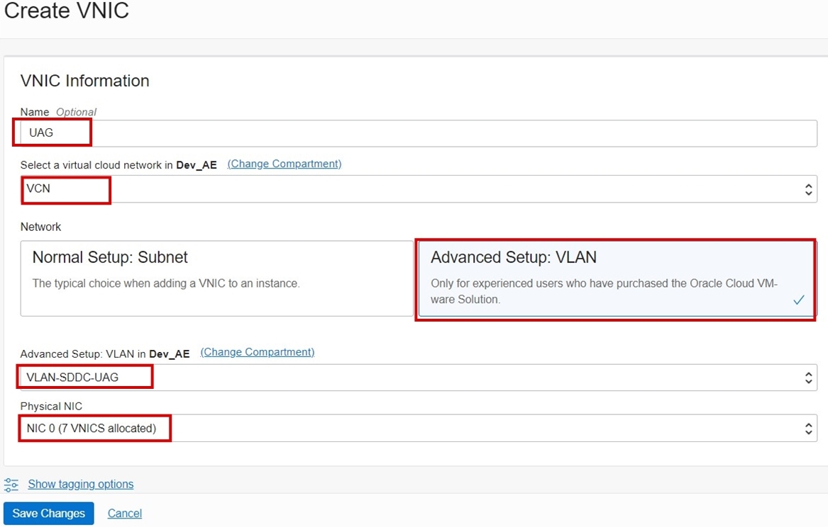
Under Resources, select Attached VNICs and click Create VNIC.
-
In VNIC Information, in the Name field, provide a name. Under Network, select Advanced Setup: VLAN. From the Advanced Setup drop-down list, select VLAN-SDDC-UAG, which was previously created for the UAG and physical network adapter card. From the Physical NIC drop-down list, select NIC 0.
Note: Make sure that you do not select NIC 1.
-
-
Repeat the step above to add the virtual network interface cards (vNICs) on all bare metal ESXi nodes. In this example, perform the same steps for the SDDC-2 and SDDC-3 ESXi hosts.
-
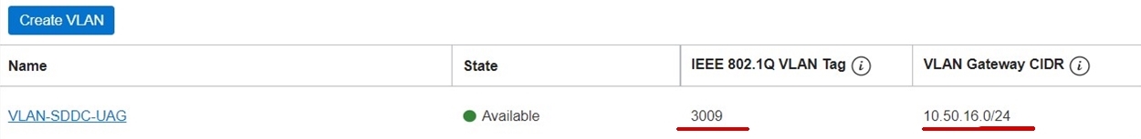
Collect the IEEE 802.1Q VLAN tag information from the Oracle Cloud Console. From the navigation menu near the top-left corner of the Oracle Cloud Console, select Networking and select Virtual Cloud Networks (VCN). Highlight the newly created VLAN and look for the IEEE 802.1Q VLAN tag. On the VLAN information page, note the VLAN tag.
Note: In this example, the VLAN tag is 3009. Your VLAN ID will vary and will be listed here.
-
Log back into the VMware SDDC environment and log in to VCenter using administrator@vsphere.local.
-
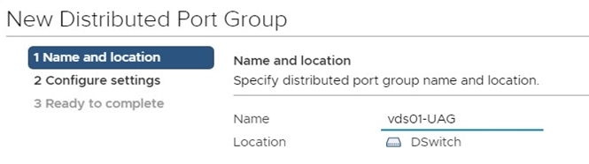
Create a new distributed port group in the vCenter server referencing the details of the newly created VLAN.
-
Click Networking, click DSwitch, click Distributed Port Group, and then click New Distributed Port Group.
-
In the Name and location section, provide a name for the distributed port group.
-
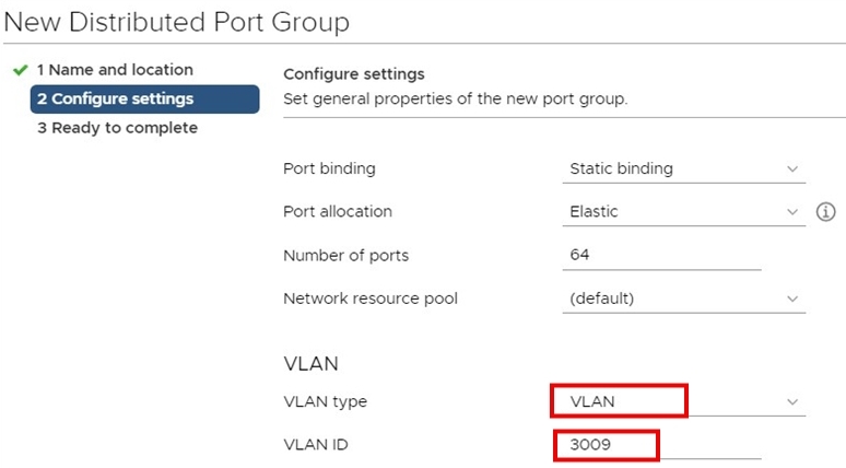
Under Configure Settings, set the port binding to Static binding, set the number of ports to 64, and add the VLAN ID.
Note: In this example, we’ve collected the VLAN ID (3009) from the Oracle Cloud Console.
-
Attach the VLAN to the SDDC Cluster in VSphere 7.0
-
From the Oracle Cloud Console, click the navigation menu, select Compute Instances and select ESXi Node (repeat this step on all applicable ESXi bare metal nodes in the Oracle Cloud VMware Solution cluster).
-
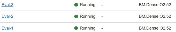
In the Compute section, click one of the ESXi hosts; in this example, it’s Eval-1.
-
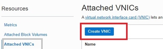
Under Resources, select Attached VNICs and click Create VNIC (you need to create two vNICs per ESXi Node).
-
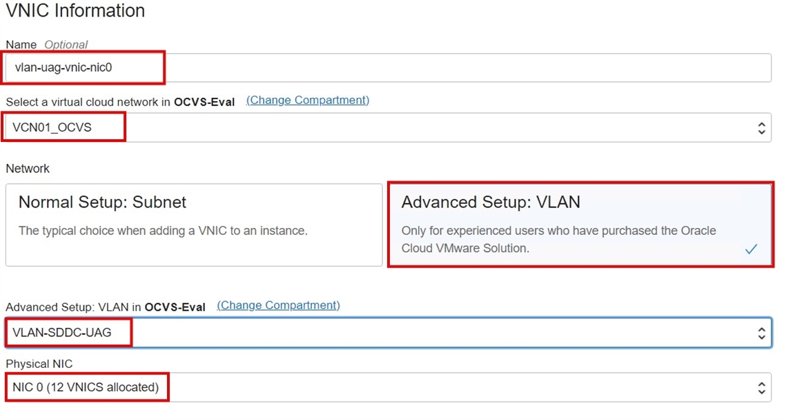
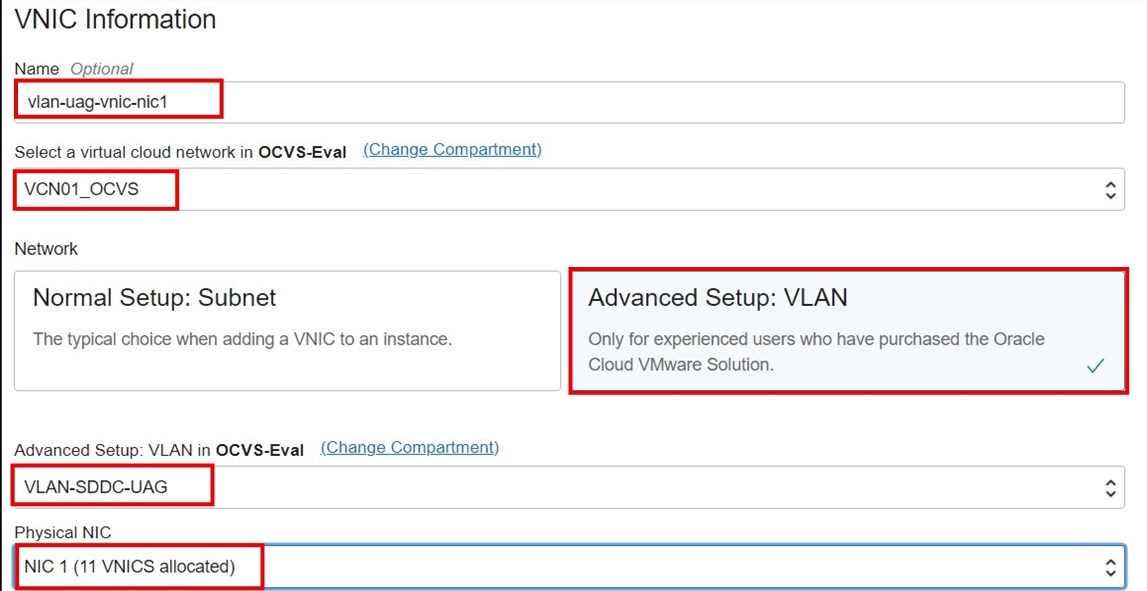
Create two VNICs. In the VNIC information dialog box, provide a name. Under Network, select Advanced Setup: VLAN and select the VLAN-SDDC-UAG previously created for the UAG and physical network adapter card. Select the physical NIC 0. Please note to repeat this same step for NIC 1.
Review the screenshot for NIC 0.
Review the screenshot for NIC 1.
Review the summary of the VNIC attachment.

-
-
Repeat step 1 to add the VNICs on all bare metal ESXi nodes. In this example, perform the same steps for Eval-2 and Eval-3 ESXi hosts.
-
Collect the IEEE 802.1Q VLAN tag information from the Oracle Cloud Console. From the navigation menu near top-left corner of the Oracle Cloud Console, select Networking, select Virtual Cloud Networks (VCN), highlight the newly create VLAN, and look for the IEEE 802.1Q VLAN tag. Under the VLAN information page, note the VLAN tag. In this example, the VLAN tag is 1052. Your VLAN ID will vary and will be listed here.
-
Log back into the vSphere 7.0 SDDC environment and log in to VCenter using administrator@vsphere.local.
-
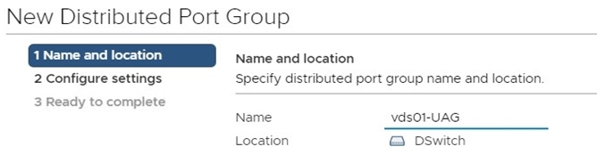
Create a new distributed port group in vCenter server referencing the details of the newly created VLAN.
-
Select Networking, select DSwitch, click Distributed Port Group and then click New Distributed Port Group.
-
In the Name and location section, provide a name for the distributed port group.
-
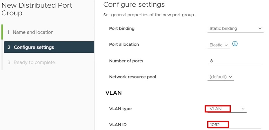
Under Configure Settings, set the port binding to Static binding, set the number of ports to 64, and add the VLAN ID.
Note: In this example, we’ve collected the VLAN ID (1052) from the Oracle Cloud Console (in the previous step).
-
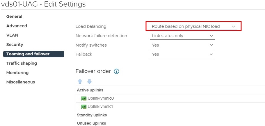
Edit the newly created distributed port group and change the load balancing policy to Route based on physical NIC load under Teaming and failover.
-
Deploy and Configure Horizon Components
This section describes the high-level steps to deploy and configure Horizon components such as connection servers, UAGs, and desktops. Since there are many preferences based on your choices, we recommend using the best practices from the VMware Horizon View Best Practices knowledge base (kb) article by VMware for the Horizon design.
Prerequisites
- The active directory domain controller with DNS service and CA server is available before starting the proceeding steps.
- The Microsoft SQL Server is installed and the event database was created. For the purpose of this tutorial, the steps for Microsoft SQL Server installation are not covered.
Deploy and Configure Connection Servers
-
Create two Windows Server VMs in SDDC for connection servers.
-
Join these two connection server VMs to the Windows Active Directory domain controller and create the necessary domain name system (DNS) records in the internal DNS server created as a prerequisite.
-
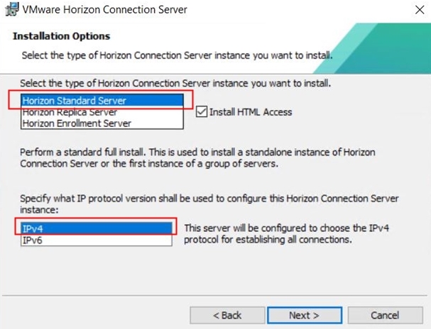
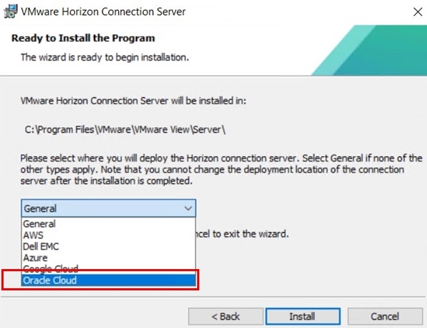
On the first connection server, select the standard deployment type.
-
Select Oracle Cloud as the deployment location and finish the installation of the first connection server.
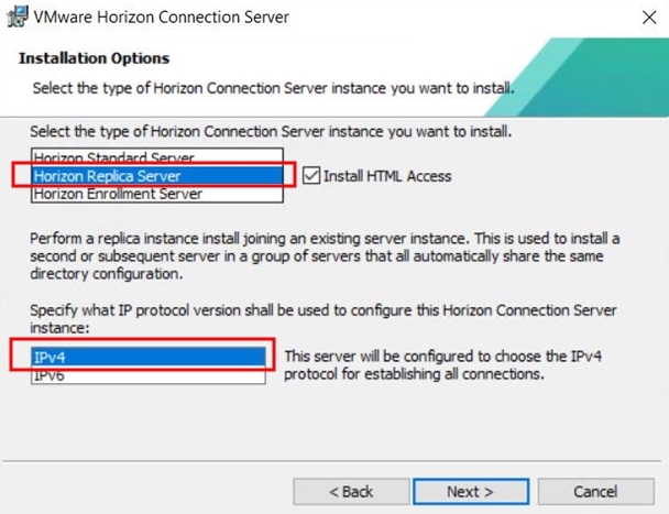
-
On the second connection server, select the deployment type as replica and point to the primary connection server from step 3. Follow the installation wizard and complete the installation of the second connection server.
-
Deploy the open virtual appliance (OVA) for Horizon Cloud Connector required for licensing. Refer to Connect Horizon Cloud Service with an Existing Horizon Pod to Use Horizon Subscription Licenses or Cloud-Hosted Services or Both for more details.
-
After the successful implementation of both connection servers, launch the administration page by going to https://your-primary-connection-server-IP/admin.
-
Enter your Horizon serial number as required.
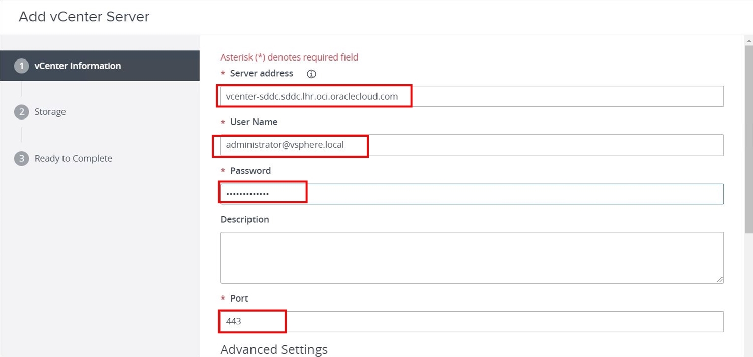
-
Under Servers, click vCenter Servers, click Add, and then enter the VCenter information.
-
Leave the default Storage page and finish the wizard.
-
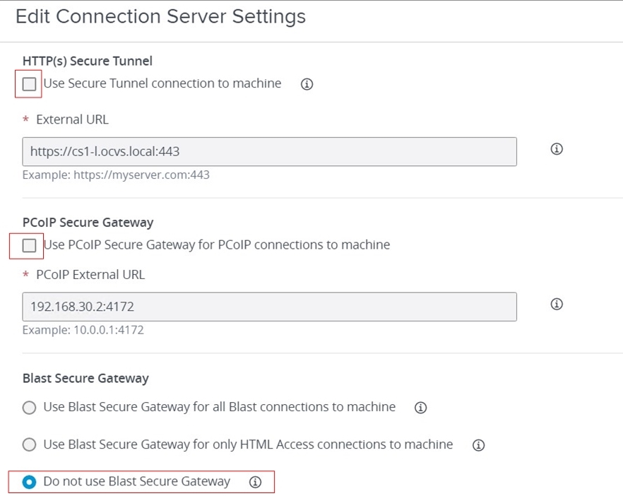
Under Servers, click Connection Servers and you should see primary and replica connection servers. Select a primary connection server and click Edit.
-
On the Edit Connection Server Settings page, clear the HTTP(s) Secure Tunnel check box, clear the PCoIP Secure Gateway check box and select the Do not use Blast Secure Gateway radio button under Blast Secure Gateway. Do this for the replica connection server as well. At this stage, the connection server is configured with the vCenter server and both the connection servers are in sync.
-
Log in to the connection server and navigate to Event Configuration under Settings and configure the event database to point to the Microsoft SQL Server database. Make sure to use
safor the username.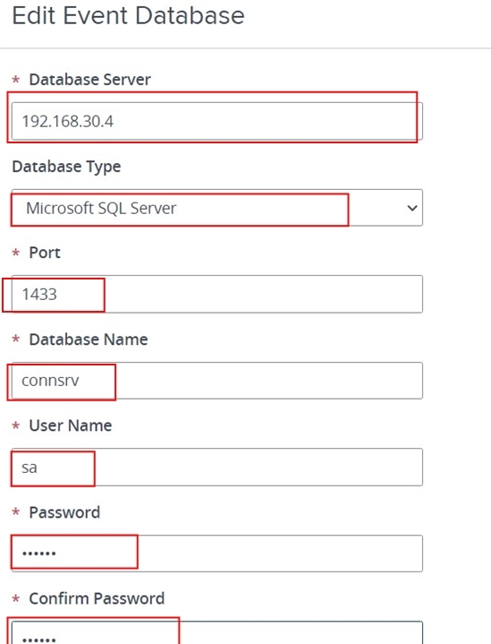
-
Note: Steps for configuring global settings, desktop pools, and farms are not in the scope of this tutorial as they may vary based on your requirements and this is a standard VMware implementation.
Deploy and Configure a UAG
We need to deploy two UAG appliances for high availability and scaling.
-
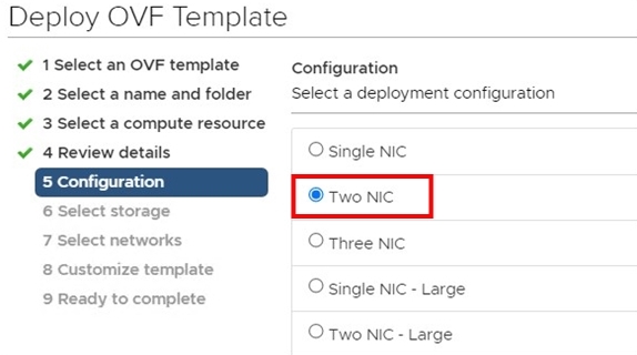
Run the Deploy OVF wizard and select the UAG Non-Federal Information Processing Standards (FIPS) UAG OVA bundle. Select the compute resources as desired.
-
On the configuration page, select Two NIC and click Next.
-
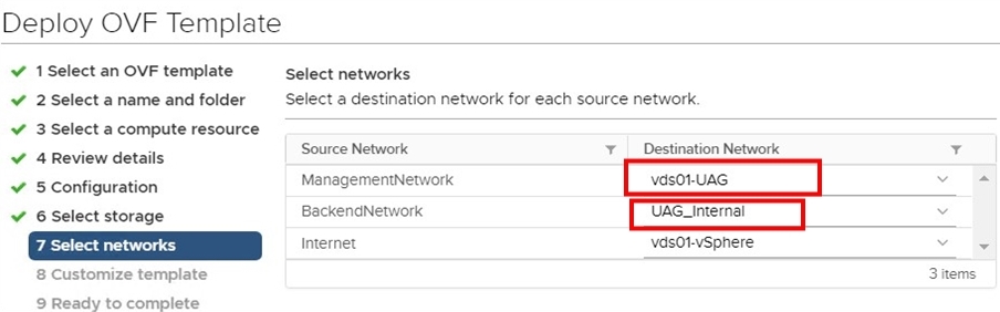
In the Select networks section, select ManagementNetwork as the UAG distributed port group and select BackendNetwork as the UAG internal overlay segment created in an NSX environment. Leave the default for Internet network and click Next.
-
Under Customize template, select Networking Properties, select STATICV4 and configure the IPv4 address from the UAG VLAN network. Specify the unique identifier name for the Unified Gateway Appliance Name.
-
Under Password Options, set the root and admin password.
-
Under System Properties, enable SSH and finish the wizard.
-
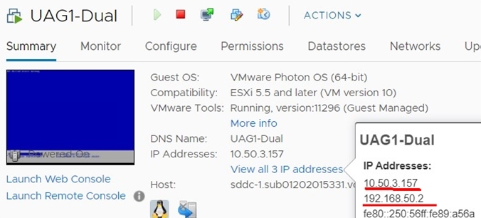
Power on the UAG appliance. You should see two IP address, one from UAG VLAN and the other from the NSX overlay UAG internal segment.
-
Log in to Oracle Cloud Console and navigate to Networking, select Virtual Cloud Networking, select SDDC VCN, select VLAN, and then select VLAN-SDDC-UAG VLAN. Create external access to get the public IP addresses for your UAGs.
-
Click Add External Access and select Public Access as the External Access Type.
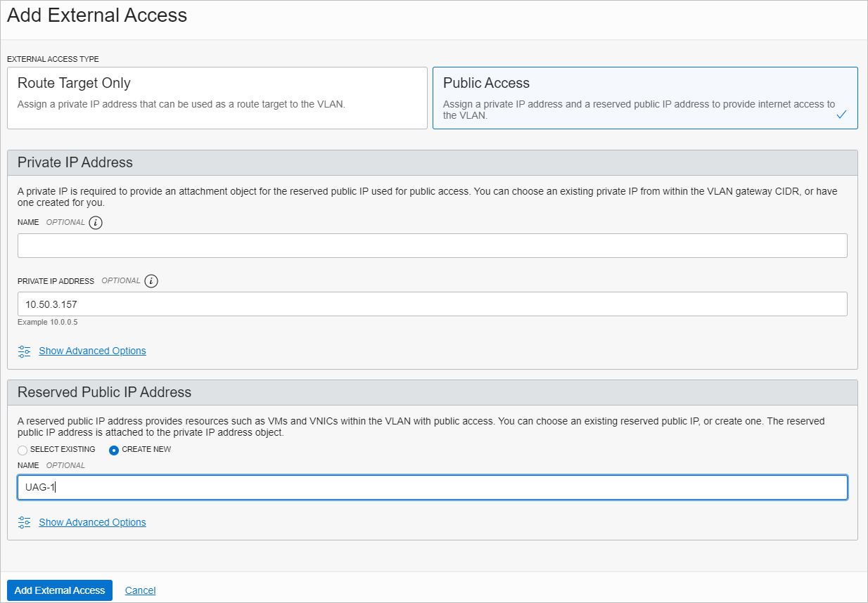
-
Enter the private IP address from the UAG VLAN of the first UAG appliance. In this example, its 10.50.3.157.
-
In the Reserved Public IP Address section, select CREATE NEW, specify a unique name and click Add External Access.
Note: You will see private to public IP address mapping for your UAG appliance as a result of completing steps 8 to 10.
-
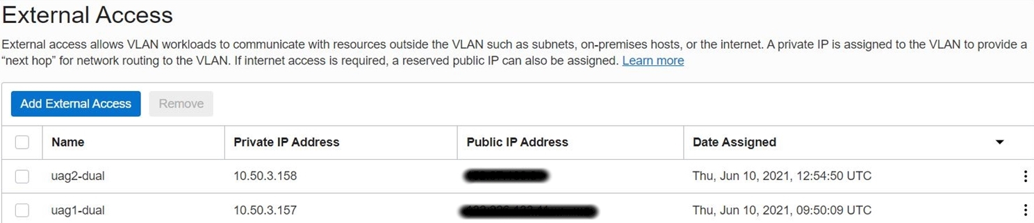
Repeat steps 1 to 11 for second UAG appliance.
Note: At this stage, you have one public IP addresses for each UAG appliance.
-
Create a public DNS record using the public IP address received in step 8 for each UAG appliances. Next, let’s create routes from the UAG appliance for communication to the load balancer segment and connection servers.
Note: Communication occurs between the bastion host and the NSX overlay segment for management purposes, which is required for UAG appliance management through the web GUI.
-
Create an entry in the bastion host public subnet with the private IP as a target type to NSX Edge VIP IP address for destination 192.168.0.0/16 (applicable if you want to access the UAG appliances web GUI from the bastion host).
-
Log in to UAG console from vSphere using the root user and add route entries.
-
Add these routes after the load balancer is deployed and configured. These two IP address belong to the UAG load balancer health check instances.

The screenshot shows the route entry for the entire range for the explicit route from the overlay gateway.

This screenshot shows the overlay network to cover all segments part of this deployment.

This screen shot shows the summary of the routes from the UAG appliance.
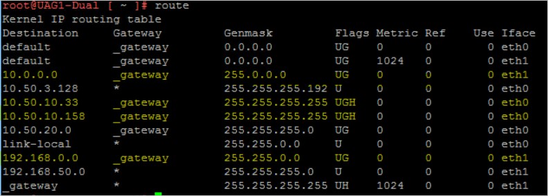
Note:
- eth0 is from the VLAN backed network and eth1 is from the Overlay segment. Refer to the yellow-marked route rules.
- Before you proceed with the next steps, make sure to complete the private load balancer configuration for the connection server to obtain LBaaS virtual IP (VIP). Refer to the Deploy and Configure Private Load Balancer section. Come back to step 18 after completing the load balancer configuration.
-
Create a DNS record for the connection server load balancer VIP that you obtained.
-
Add entry in /etc/resolv.conf to point to the internal DNS server where all the DNS records are created. The UAG should communicate over the host name of the connection server’s load balancer LB VIP.
-
Configure UAG appliances by accessing the appliance web page using https://
:9443/admin. -
Log in with administration credentials and enable Edge Service Settings under General Settings.
-
Provide the connection server URL.
Note: This URL should be the internal DNS entry of the private load balancer VIP, which load balances both standard and replica connection servers. For private load balancer configuration, refer to the note on private LBaaS configuration after step 15.
-
Paste the connection server URL thumbprint and make sure to include both connection server’s sha1 thumbprint.
-
To get thumbprint access to the connection server URL using https://primary-connection-server/admin, click padlock, click Certificate, click Details, and then click Thumbprint.
-
To get the thumbprint for the replication server, repeat step 22a.
-
Combine both thumbprints in one line:
sha1=6b 8f 21 f5 e3 7d ce 7f b0 8d 33 88 92 96 2b e9 86 3a 24 b3,sha1=6f 5d 57 77 90 30 cd 64 eb ae bf ce b4 82 7e ae 11 b3 65 4f
-
-
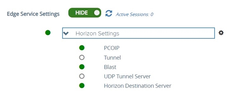
Enable PC over IP (PCoIP) and enable Disable PCOIP Legacy Certificate.
-
In the PCOIP External URL field, enter the public IP address for the UAG appliance with port 4172; for example, 150.100.222.23:4172.
-
On the Horizon Settings page, select Enable Blast and enter the Blast External URL as the public DNS record associated with the UAG appliance with port 8443. For example,
https://xyz.company.com:8443where thexyz.company.comis the public DNS host record for the IP address 150.100.222.23.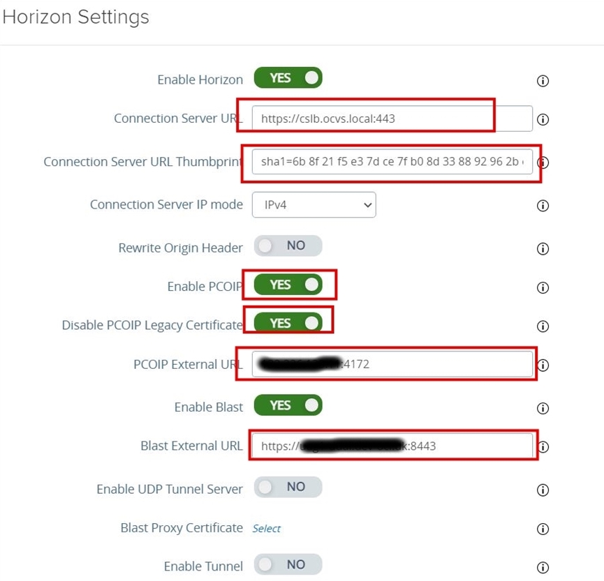
-
Repeat steps 1 to 25 for the second UAG appliance.
-
You should see the statuses as green in the UAG appliance web GUI after a successful configuration.
-
Log in to the connection servers web GUI and check if the UAGs are registered. Select Settings, select Servers, and click Gateways.
Select an Oracle Cloud Infrastructure Load Balancing (LBAAS) Option For Horizon
To select the appropriate Horizon load balancing methodology, you must decide on the ingress and egress traffic patterns for the desktop userbase. The following are commonly used options:
Method 1: Perform for internal-facing clients only (users connect to connection servers)
In this method, connections are generated only within the internal networks and clients may connect directly to the connection servers located on the SDDC network. In this case, the UAG/Gateways may need to be bypassed so the clients can access the desktops.
- Perform only a private load balancer configuration.
- Refer to the Deploy and Configure Private Load Balancer section.
Method 2: Perform for internal and external user access
In this method, both the public and private load balancers are deployed.
- Refer to the Deploy and Configure a Public Load Balancer section.
- Refer to the Deploy and Configure a Private Load Balancer section.
Deploy and Configure a Private Load Balancer
This section describes steps to configure Oracle Cloud Infrastructure (OCI) native LBaaS for connection servers. Refer to the following architecture for more details.
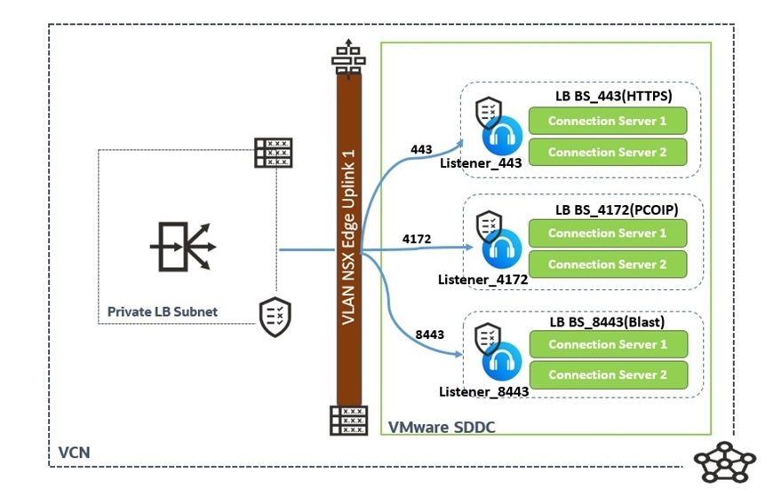
Note: The following table lists the backend, listener, and port and protocol configuration for the LBaaS.
| Backend Sets | Backends | Listener | Port | Protocol |
|---|---|---|---|---|
| BS_443 (HTTPS) | Connection Server 1 & Connection Server 2 | Listener_443 | TCP | 443 |
| BS_4172 (PCOIP) | Connection Server 1 & Connection Server 2 | Listener_4172 | TCP | 4172 |
| BS_8443(Blast) | Connection Server 1 & Connection Server 2 | Listener_8443 | TCP | 8443 |
-
Log in to Oracle Cloud Console and navigate to Networking and select Load Balancers. Change the region and compartment to your desired compartment and region.
-
Click Create Load Balancer and select Load Balancer for the Type. Do not select Network Load Balancer.
-
Specify the name of the load balancer and select Private for the visibility type. In the bandwidth section, select Flexible Shapes and chose the required minimum and maximum bandwidth.
-
Select the VCN and private subnet created in the previous steps to host the private LBaaS. Click Next.
-
Select IP Hash as a load balancing policy.
Note: Do not add backends at this stage (we will do that later).
-
Select the Health check policy protocol as TCP and change the port to 443. Leave the default settings for intervals and timeouts. Click Next to add a listener.
-
Specify the name of the listener and select TCP as your listener traffic type. Specify
443as the port and leave the default settings.Note: If you are planning to use CA signed certificates, chose HTTPS as the listener traffic type and upload the valid SSL certificates. For more details, refer to the OCI LBaaS documentation.
-
Click Submit and wait for the LB status to turn green.
-
In the next step, add the backends and listeners according to the table earlier in this section.
-
Make a note of the LBaaS private IP and create an internal DNS record that will be referred to as Horizon connection server’s VIP URL.
-
Add the route rule for the Private LBaaS subnet with the target type as NSX overlay VIP. The following screenshot shows the route table for private LBaas. The example shows 192.168.0.0/16 is the NSX overlay subnet for management and 10.50.0.131 is the uplink interface for NSX Edge Uplink VLAN. This will cover all three overlay segments.

-
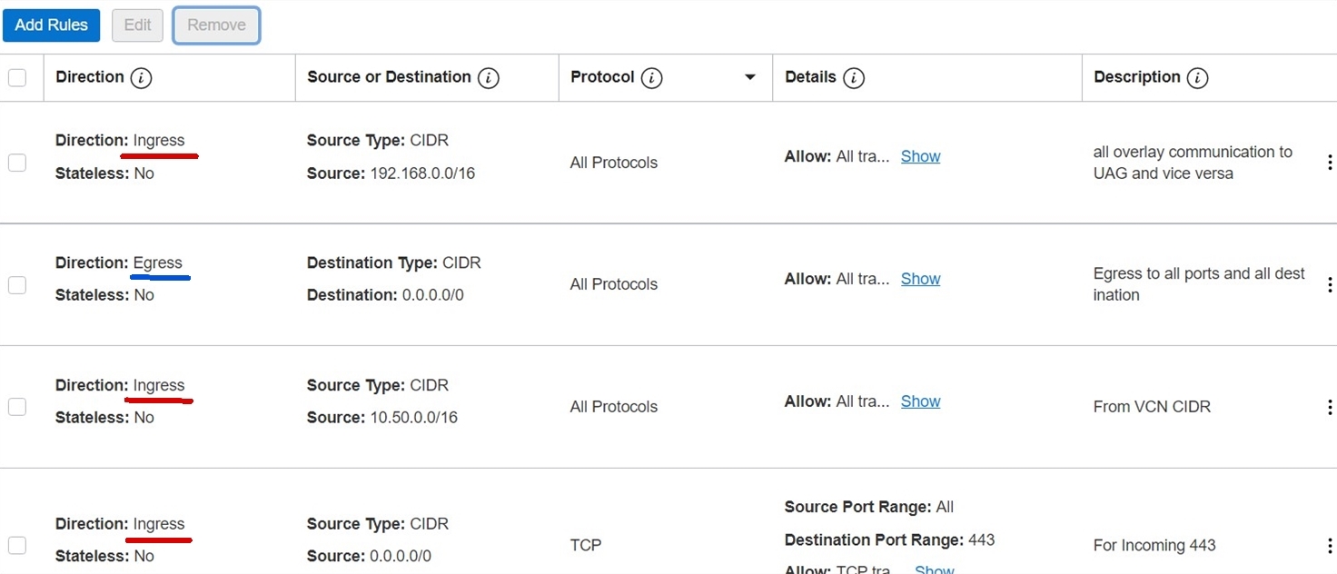
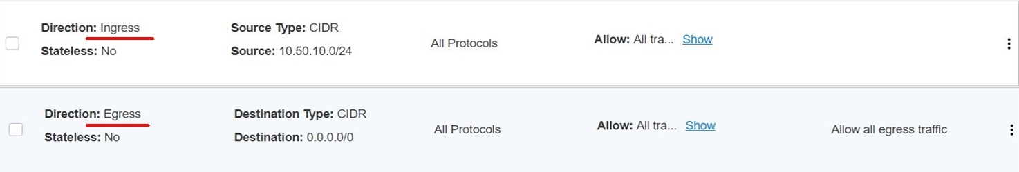
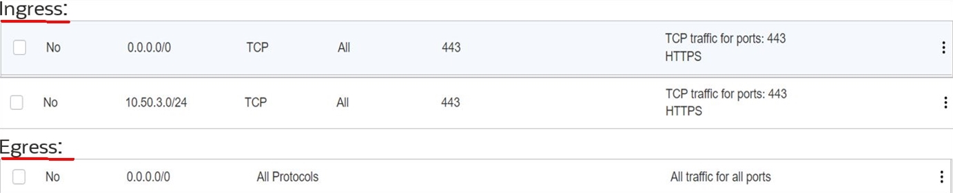
Update the private LBaaS subnet security rule to accept the communication from the NSX overlay segment. The following screenshots show the security list for the private load balancer. The security rule accepts the communication from the NSX overlay subnet to LBaaS.
Ingress:

Egress:

-
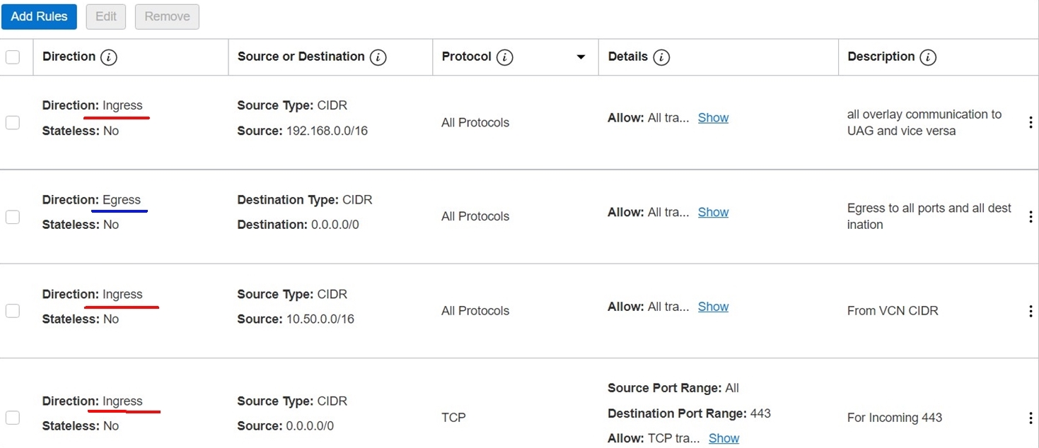
Update the network security group for NSX-Edge-Uplink1 to accept the communication from the LBaaS private subnet. The screenshot bellows shows the NSX-Edge-Uplink1 network security group where 10.50.10.0/24 is the LBaaS private subnet CIDR.
-
Deploy and Configure a Public Load Balancer
This section describes steps to configure Oracle Cloud Infrastructure (OCI) native LBaaS for UAG external access. Refer to the following architecture for more details.
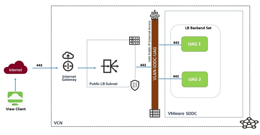
Note: The following table lists the backend, listener, and port and protocol configuration for the LBaaS.
| Backend Sets | Backends | Listener | Protocol | Port |
|---|---|---|---|---|
| BS_443 (HTTPS) | Unified Access Gateway 1 & Unified Access Gateway 2 | Listener_443 | TCP | 443 |
-
Log in to Oracle Cloud Console and navigate to Networking and select Load Balancers. Change the region and compartment to your desired compartment and region.
-
Click Create Load Balancer and select Load Balancer as a Type. Do not select Network Load Balancer.
-
Specify the name of the load balancer and select Public as the visibility type. Click Reserved IP Address and select the Create new reserved UP address radio button. Provide the name of the IP and select the compartment.
-
In the Bandwidth section, select Flexible Shapes and chose the required minimum and maximum bandwidth.
-
Select the VCN and public subnet created in the previous steps to host the public LBaaS. Click Next.
-
Select IP Hash as the load balancing policy.
Note: Do not add backends at this stage, we will do that later.
-
In the Specify Health Check Policy section, select TCP and change the port to
443. Leave the default settings for intervals and timeouts. Click Next to add a listener. -
Specify the name of the listener and select TCP as your listener traffic type. Specify port 443 and leave default settings.
Note: If you are planning to use CA signed certificates, chose HTTPS as the listener traffic type and upload the valid SSL certificates. For more information, refer to the OCI LBaaS documentation.
-
Click Submit and wait for the LB status to turn green.
-
In the next step, add the backends and listeners according to the table earlier in this section.
-
Make a note of the LBaaS public IP and create an external DNS record for public access to the VDI infrastructure.
-
Add the route table entry for the public load balancer subnet.
The following screenshot shows the route table entry for the public LBaaS subnet:
The following screenshot shows the route table entry for VLAN-SDDC-UAG. We covered this step while creating the UAG VLAN. If you followed the UAG VLAN creation steps, you should see a similar route entry in the route table for the UAG VLAN.
The following screenshot shows the Network communication-Security list and network security group rules for public LBaaS. In this example, 10.50.3.0/24 is a VLAN subnet for horizon UAG appliance.
The following screenshot shows the network security group for SDDG UAG VLAN. This step is already covered during the UAG VLAN creation process in the initial steps. If you followed the UAG VLAN creation steps, you should see a network security group similar to screenshot below.
After you finish the public and private load balancer configuration, the Horizon setup can be tested using Horizon Client.
Acknowledgements
- Authors - Devendra Gawale (Cloud Solution Architect)
- Contributors - Moin Syed (Solution Architect), Adeel Amin (Cloud Solution Architect)
More Learning Resources
Explore other labs on docs.oracle.com/learn or access more free learning content on the Oracle Learning YouTube channel. Additionally, visit education.oracle.com/learning-explorer to become an Oracle Learning Explorer.
For product documentation, visit Oracle Help Center.
Install and configure VMware Horizon on Oracle Cloud VMware Solution
F44912-02
November 2021
Copyright © 2021, Oracle and/or its affiliates.