Note:
- This tutorial requires access to Oracle Cloud. To sign up for a free account, see Get started with Oracle Cloud Infrastructure Free Tier.
- It uses example values for Oracle Cloud Infrastructure credentials, tenancy, and compartments. When completing your lab, substitute these values with ones specific to your cloud environment.
Adding Security to the Domain Name System Architecture using pfSense Firewall
Introduction
OraStage is a leading company in the energy sector, specializing in renewable energy solutions and innovative power technologies, the company announced a strategic decision to migrate its workloads to Oracle Cloud Infrastructure (OCI) to enhance performance, scalability, and security.

Taking into account the specific needs and conditions that OraStage has outlined, the company requires a hybrid Domain Name System (DNS) solution in the cloud, and by hybrid here means to use their own Berkeley Internet Name Domain version 9 (BIND9) DNS system in addition to OCI DNS service, where the final architecture they are looking to build is shown in the following image.
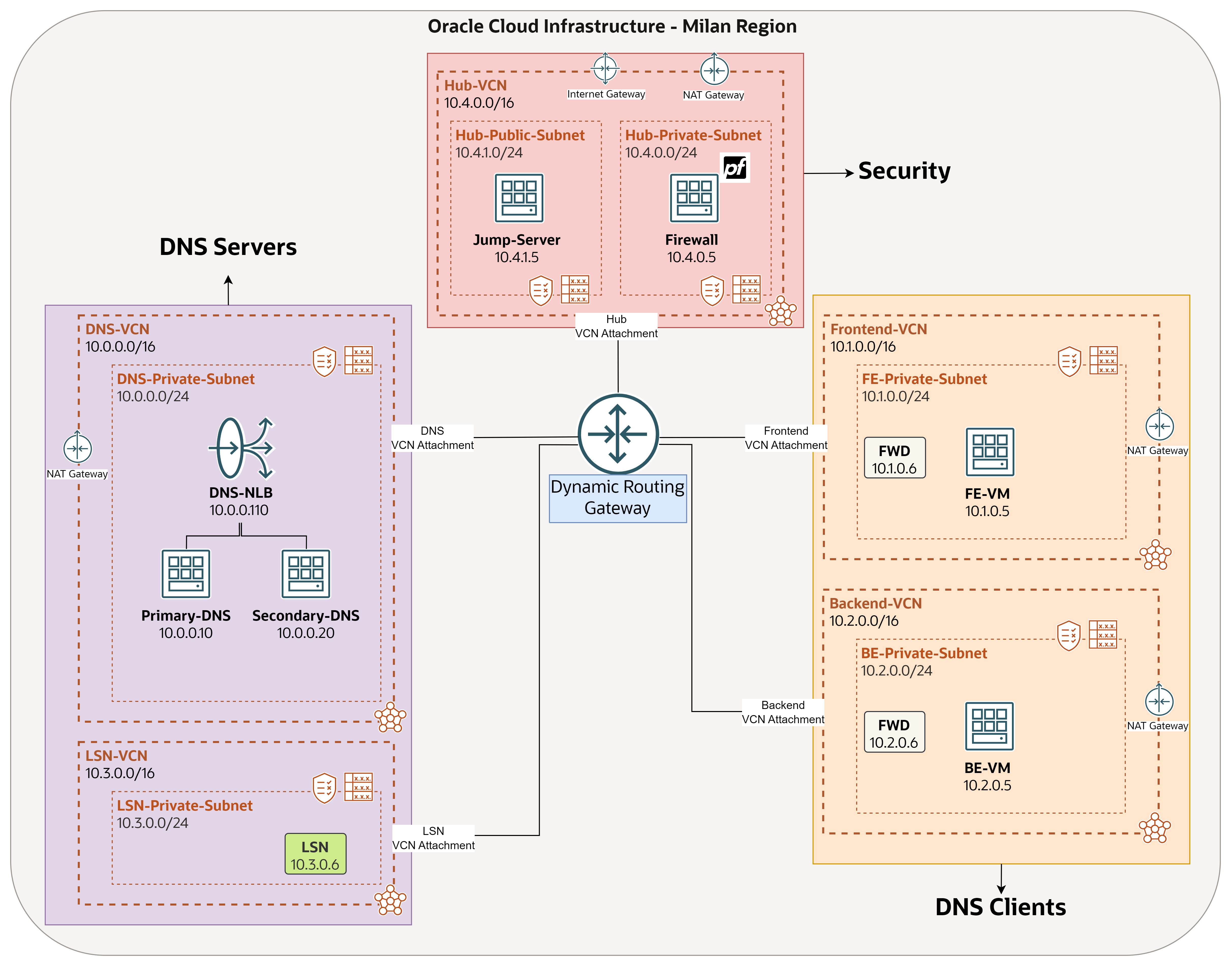
OraStage DNS requirements:
-
The company has several internal domains and subdomains, all of them should be resolved by their BIND9 DNS in OCI, where OraStage will manage all the related zones and records. One of these domains is
orastage.comwhich we are going to use in this tutorial. So, any query toorastage.commust be forwarded to their BIND9. -
They still need to resolve OCI native domains (
oraclevcn.com,oraclecloud.com, and so on) in some cases, and this is going to be done by using OCI private DNS components: private views, forwarding endpoints and rules, and listening endpoints. -
All the queries must be inspected by a pfSense firewall instance.
-
To avoid single point of failure, OraStage plan to use another DNS server and leverage OCI Load Balancer to distribute queries between primary and secondary DNS.
This tutorial series will guide you step by step to achieve the outlined requirements above, building the entire solution from scratch. You can easily navigate to each tutorial from the list below:
-
Tutorial 1: Configure BIND9 DNS in OCI. Learn how to install and configure BIND9 on a compute instance, making it the local DNS server for two test environments in OCI. These environments will consist of “Frontend” and “Backend” servers, each hosted in a separate spoke network. The BIND9 server will handle all DNS queries directed to
orastage.com. -
Tutorial 2: Implement High Availability on BIND9 DNS scenario in OCI. This tutorial focuses on adding a secondary BIND9 server and configuring a Network Load Balancer (NLB) to distribute DNS traffic between both servers. DNS queries to
orastage.comwill be directed to the NLB IP, which will balance the load between the primary and secondary BIND9 servers. If one server becomes unavailable, DNS resolution will continue without service interruption. -
Tutorial 3: Use OCI DNS to resolve native domains. Focusing only on a specific use case, where we utilize native DNS components in OCI, in case there is a need to resolve native domains such as
oraclevcn.comandoraclecloud.com. BIND9 DNS is not used in this tutorial. -
Tutorial 4: Adding security to the DNS architecture using pfSense Firewall. Focusing on installing a pfSense Firewall in the hub VCN in OCI, and do the required network configuration to route all East-West traffic including DNS queries (done in the past tutorials) through the firewall to be inspected.
Overview
In this tutorial, we will explore how to enhance the security of our DNS architecture by leveraging pfSense, an open-source firewall and router platform.
DNS is a critical component of network infrastructure, but it is often vulnerable to attacks like DNS spoofing, cache poisoning, and Distributed Denial of Service (DDoS). By integrating pfSense with DNS security measures, you can add a robust layer of protection, ensuring your network’s DNS traffic is secure and resilient. So, it is recommended to configure your firewall in a way to filter DNS queries, block malicious domains, and strengthen overall DNS integrity.
What is the added benefit of placing a pfSense firewall in front of a DNS server?
-
Traffic Filtering and Access Control
-
The firewall can restrict access to your DNS server, allowing only authorized IP addresses or specific networks to send DNS queries. This prevents unauthorized users or systems from querying or exploiting the server.
-
It can enforce access control policies to ensure that only legitimate DNS traffic reaches the server, blocking potentially harmful or unwanted traffic.
-
-
Protection from DNS-Based Attacks
-
DNS Amplification/Reflection Attack Prevention: Firewalls can detect and mitigate DNS amplification attacks, where attackers send spoofed requests to overwhelm the server. By limiting or rate-limiting DNS query traffic, the firewall minimizes the impact of such attacks.
-
DNS Spoofing Prevention: Firewalls can block rogue or malicious DNS responses, which are used in DNS spoofing or poisoning attacks to misdirect users to fraudulent websites.
-
DDoS Mitigation: Firewalls provide defense mechanisms against Distributed Denial of Service (DDoS) attacks by monitoring and throttling abnormal DNS traffic volumes, preventing attackers from overwhelming your DNS infrastructure.
-
-
DNS Query Inspection and Logging
- The firewall can inspect DNS queries for suspicious patterns, such as queries for known malicious domains. It can block these queries before they reach the DNS server, helping to prevent access to dangerous sites.
- DNS query logs can be recorded for auditing purposes, allowing you to detect abnormal behaviour or investigate potential security incidents more effectively.
-
Prevention of DNS Tunnelling
- DNS tunnelling is a technique used by attackers to exfiltrate data or communicate with compromised systems via DNS queries. A firewall can detect and block DNS tunnelling activities, closing off a significant data-leakage vector.
-
Rate Limiting and Resource Protection
- The firewall can limit the number of DNS requests coming from a single source (rate limiting), preventing overloading of the DNS server. This helps to protect against brute force or excessive DNS query attacks that could degrade the server’s performance or availability.
-
Network Segmentation
- By placing the DNS server behind a firewall, you can isolate it within a protected network segment (for example, DMZ), ensuring that even if the DNS server is compromised, the attacker’s access to the rest of your network is restricted.
-
Support for Secure DNS Protocols
- Firewalls can enforce secure DNS protocols like DNS over HTTPS (DoH) or DNS over TLS (DoT), ensuring that DNS traffic is encrypted. This prevents eavesdropping or tampering with DNS queries and responses, protecting users from man-in-the-middle attacks.
-
Reducing Attack Surface
- By hiding the DNS server’s real IP address behind the firewall, you reduce its exposure to potential attackers. The firewall acts as an intermediary, presenting a layer of defense between the public internet and your DNS infrastructure.
Overall, placing a firewall in front of your DNS server enhances the server’s security, performance, and resilience by preventing unauthorized access, detecting malicious traffic, and offering robust protection against a wide range of DNS-related threats.
Objectives
-
The primary objective of this tutorial is to route all East-West traffic, including DNS queries, through a pfSense firewall to be inspected. Additionally, we will monitor some requests using the firewall’s packet capture feature.
-
We will also deploy a public Windows jump server, which will serve as an access point for managing other private instances within OCI VCNs, particularly the pfSense firewall.
-
By the end of this tutorial, our goal is to establish a hub & spoke network architecture model. This setup will enhance security, streamline network management for OraStage by centralizing routing control between networks through the hub, and increase scalability, allowing the company to add new networks to the existing hub any time.
Note:
This tutorial does not cover protection capabilities against DNS specific attacks. Instead, our focus is on deploying the pfSense firewall and integrating it to the existing environment to route all traffic through it (for example, FE-VM to BE-VM, FE-VM to DNS-NLB, and so on). We will also demonstrate how to configure basic access control rules on the firewall.
You can still follow this tutorial even if you already have another type of firewall solution in place such as OCI Network Firewall or a marketplace network firewall like Palo Alto or FortiGate, among others.
Final architecture

Prerequisites
-
Access to an OCI tenancy and permissions to manage the required network, compute, and object storage services.
-
Basic understanding of OCI network routing and security and their functionalities: Virtual Cloud Network (VCN), Route Table, Dynamic Routing Gateway (DRG), Security List, Bastion, and OCI Network Load Balancer.
-
Basic understanding of DNS in general.
-
Make sure to complete the following tutorials:
-
One VCN is required, make sure to create it with the wizard so you get all the needed default components within the VCN and attach it to the DRG. For more information, see Task 1.3: Attach VCNs to the DRG.
- Hub-VCN: Public subnet will host the jump server, and private subnet will host the pfSense firewall.
-
Based on the above Prerequisites, you should have already built the following architecture.

Task 1: Set up Routing and Security Network Components
Task 1.1: Create a Virtual Cloud Network (Hub-VCN)
Make sure you have the Hub-VCN (10.4.0.0/16) already created, containing Hub-Private-Subnet (10.4.0.0/24) and Hub-Public-Subnet (10.4.1.0/24).
-
Click the hamburger menu (≡) from the upper left corner.

- Click Networking.
- Click Virtual cloud networks.

-
We can see the VCN in place, as mentioned, make sure to create it using the wizard, so you will get the following components by default: three gateways, one public subnet with a route table and a security list attached to it, and one private subnet with a route table and a security list attached to it.

Note:
From now on, within some parts of route tables and security lists configuration, we are going to aggregate all the networks: DNS-VCN (
10.0.0.0/16), Frontend-VCN (10.1.0.0/16), Backend-VCN(10.2.0.0/16), LSN-VCN (10.3.0.0/16), Hub-VCN (10.4.0.0/16), into just one address block (10.0.0.0/8), just for easier management as this will reduce the number of rules.In some scenarios, within a hub & spoke topology, spoke networks might need to get internet access from the hub network, in order for the traffic to pass through the firewall for better security, that is why on the spoke subnets level we are going to route all traffic to the DRG. However in this tutorial, we are not demonstrating internet access scenarios.
Task 1.2: Configure Routing and Security for Hub-VCN
-
This must be done on each of the two subnets. Navigate to the VCNs page and click Hub-VCN.

-
We are going to start with the public subnet, click it.

-
Click Route Table, which is an assigned route table.

-
Add the following rule.
0.0.0.0/0- Internet Gateway: To have bidirectional access to the Internet. We need it to access the jump server with its public IP address.

-
Let us do the security for the public subnet. Go to the Subnet Details page and click the assigned security list.

-
Allow ingress traffic: RDP traffic (TCP/port 3389) from anywhere.

-
Allow all the egress traffic.

-
Navigate back to the VCN page and click the private subnet.

-
Click Route Table, which is an assigned route table.

-
Add the following rules.
-
0.0.0.0/0- NAT Gateway: To have unidirectional access to the Internet, to install packages or patches if needed. It is not a critical component to have in this tutorial, but good to have it if pfSense needs Internet access. -
10.0.0.0/8- DRG: Route traffic destined to Frontend-VCN, Backend-VCN, DNS-VCN, or LSN-VCN to the DRG, as when the firewall is done with inspecting the traffic, it will forward the permitted traffic out, which will use this route table and send it to the DRG.

-
-
Let us do the security for the private subnet. Go to the Subnet Details page and click the assigned security list.

-
Allow ingress traffic: All types of traffic from Frontend-VCN, Backend-VCN, DNS-VCN, and LSN-VCN.

-
Allow all the egress traffic.

Task 1.3: Configure Routing and Security for LSN-VCN
-
This must be done on the subnet level. Navigate to the VCNs page and click LSN-VCN.

-
Click the private subnet.

-
Click Route Table, which is an assigned route table.

-
We will delete all the rules.

-
We will replace all the following rules with only one rule.
0.0.0.0/0- DRG: Route all traffic to the DRG, that includes traffic going to any of the other VCNs, and traffic going to the Internet.

-
Let us do the security now. Go to the Subnet Details page and click the assigned security list.

-
We will delete all the ingress rules that allow DNS traffic.

-
We will replace the following rules with only these two rules.

Note: Do not change anything in the egress rules.
Task 1.4: Configure Routing and Security for DNS-VCN
-
This must be done on the subnet level. Navigate to the VCNs page and click DNS-VCN.

-
Click the private subnet.

-
Click Route Table, which is an assigned route table.

-
We will delete all the following rules.

-
We will replace the following rules with only one rule.
0.0.0.0/0- DRG: Route all traffic to the DRG, that includes traffic going to any of the other VCNs, and traffic going to the Internet.

-
Let us do the security now. Go to the Subnet Details page and click the assigned security list.

-
We will delete all the ingress rules that allow DNS traffic.

-
We will replace the following rules with only these two rules.

Note: Do not change anything in the egress rules.
Task 1.5: Configure Routing and Security for Frontend-VCN
-
This must be done on the subnet level. Navigate to the VCNs page and click Frontend-VCN.

-
Click the private subnet.

-
Click Route Table, which is an assigned route table.

-
We will delete all the following rules.
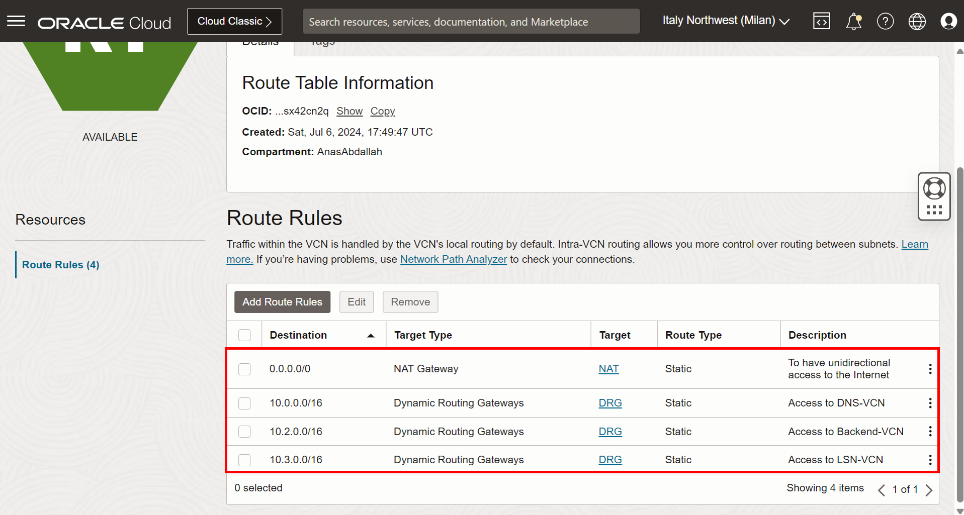
-
We will replace the following rules with these two rules.
-
0.0.0.0/0- DRG: Route all traffic to the DRG, that includes traffic going to any of the other VCNs, and traffic going to the Internet. -
All LIN Services in Oracle Services Network - Service Gateway: To provide access to Oracle services in Milan region, this is needed to keep the connectivity with OCI Bastion service, if you do not have a rule here to access the Internet or Oracle services, then you will face an error with the bastion plugin where you will not be able to use bastion to access FE-VM.

Note: Do not change anything in the ingress and egress rules.
-
Task 1.6: Configure Routing and Security for Backend-VCN
-
This must be done on the subnet level. Navigate to the VCNs page and click Backend-VCN.

-
Click the private subnet.

-
Click Route Table, which is an assigned route table.

-
We will delete all the following rules.

-
We will replace the following rules with these two rules.
-
0.0.0.0/0- DRG: Route all traffic to the DRG, that includes traffic going to any of the other VCNs, and traffic going to the Internet. -
All LIN Services in Oracle Services Network - Service Gateway: To provide access to Oracle services in Milan region, this is needed to keep the connectivity with OCI Bastion service, if you do not have a rule here to access the Internet or Oracle services, then you will face an error with the bastion plugin where you will not be able to use bastion to access BE-VM.

-
Note: Do not change anything in the ingress and egress rules.
Task 1.7: Configure Spoke VCNs Routing on DRG
The purpose for this task is to make sure all traffic sent out of any of the networks (DNS/LSN/Frontend/Backend) and received on the DRG, to be routed towards the hub, where it will be inspected by the firewall.
-
Click the hamburger menu (≡) from the upper left corner.

- Click Networking.
- Click Dynamic routing gateway.

-
Click DRG.

- Click VCN attachments. A VCN attachment represents a link that connects the VCN to the DRG to enable network traffic between the VCN and external networks or other VCNs.
- You will notice that we have all the VCNs attached.

- Click DRG route tables.
- Click Create DRG route table.
- Enter a name for the route table.
- Add a route rule: Select
0.0.0.0/0and Hub VCN Attachment which routes everything to the hub attachment. - Click Create DRG route table.
- Route table is created successfully.

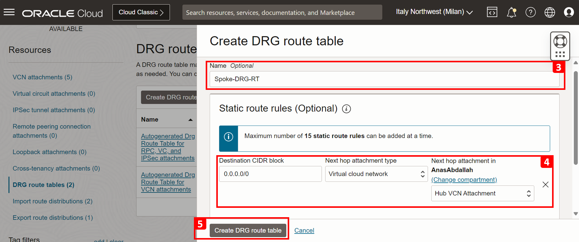

-
Assign the route table to all of the spoke VCN attachments, starting with the Backend VCN Attachment and click it.

- Click Edit.
- Click Show advanced options.
- Click DRG route table.
- Select Spoke-DRG-RT.
- Click Save changes.
- DRG route table is assigned to the Backend VCN Attachment successfully. Now all traffic coming out of the Backend-VCN to the DRG will be routed to the Hub-VCN.


-
Repeat step 1 to 6 on the rest of the attachments.

Task 2: Provision a Windows Jump Server
-
In this task, we will provision a new Windows compute instance and utilize it to connect with other private resources. The intended uses for it include:
-
(Mandatory) To access and manage the pfSense firewall through the browser (HTTP/S).
-
(Optional) To access FE-VM instance and perform the test. You can either use OCI Bastion service, or you can use this server as your new jump box.
-
-
Click the hamburger menu (≡) from the upper left corner.

- Click Compute.
- Click Instances.

-
Click Create instance.

-
Enter a Name for the instance.

- Click Change image.
- Select Windows.
- Select Windows Server 2016 Standard image.
- Select to agree the terms of use.
- Click Select image.
- Operating System (OS) of the instance is changed to Windows Server 2016 Standard successfully.


-
In Primary VNIC information section, enter the following information.
- Select Hub-VCN.
- Select the public subnet, so that the instance will be assigned a public IP address.
- Assign the instance a private IP address
10.4.1.5.

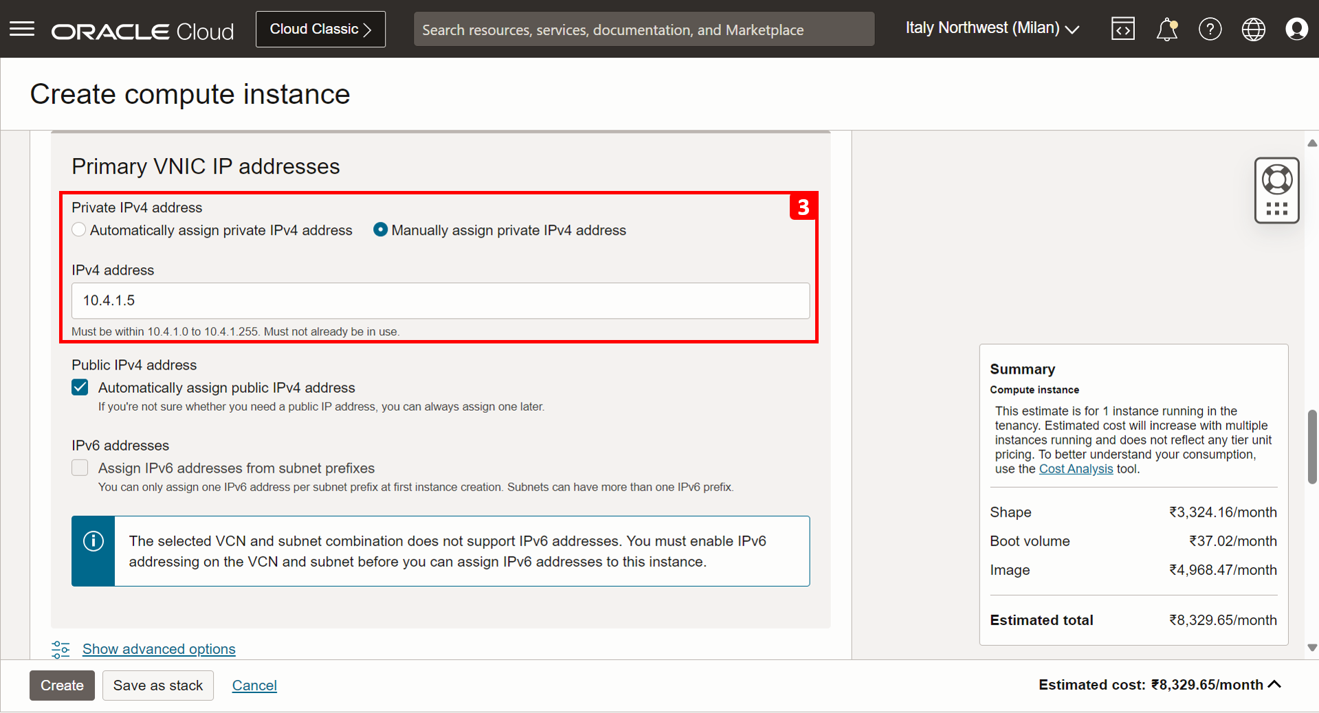
- You will observe a note when creating the Windows machine, stating that An initial password will be generated after instance creation. The difference is with Linux OS, SSH keys are used for authentication.
- Click Create.

-
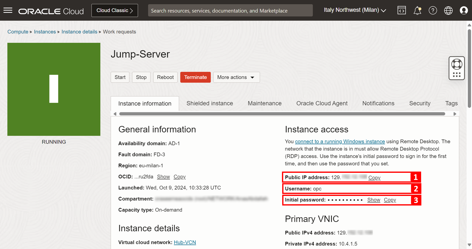
The Jump-Server compute instance is created successfully. Make a note of the following details, you will use them when accessing the instance.
- Public IP address.
- Username.
- Initial password.
-
To access the Jump-Server from your Windows personal computer, open Remote Desktop Connection, enter the public IP of the instance and click Connect.

-
Click Yes.

-
Enter the initial password provided on the instance page and click Next.

-
Password must be changed before logging in and click OK.

-
Enter your new password twice.

-
Password is changed successfully, click OK to proceed.

-
Enter your new password and click Next.

-
You are connected to the Jump-Server successfully.

-
The architecture should look as shown in the following image.

Task 3: Install and Configure pfSense Firewall
Note: If you already have another type of firewall solution in place, you can skip Task 3.1 to 3.7, and proceed from 3.8.
Task 3.1: Download the pfSense Image
-
Download the pfSense image from the Netgate website. Ensure to download the
memstick-serialversion. The filename of the image that we are using ispfSense-CE-memstick-serial-2.7.2-RELEASE-amd64.img.gz. For more information, see Netgate.
-
The file installed will be in the
.gzformat. After you extract it, you will notice the image filename ispfSense-CE-memstick-serial-2.7.2-RELEASE-amd64.img.
Task 3.2: Create an OCI Object Storage Bucket
In this task, we will create an OCI Object Storage bucket that will be used to upload the pfSense image and use this object image to create a custom image in OCI.
-
Click the hamburger menu (≡) from the upper left corner.

- Click Storage.
- Click Buckets.

- Click Create Bucket.
- Enter a Bucket Name.
- Select Standard storage tier as Default Storage Tier.
- Click Create.


-
Notice that the storage bucket is created.

Task 3.3: Upload the pfSense Image to the Storage Bucket
-
Go to the Bucket Details page.
- In the bucket page, scroll down.
- Click Upload.

-
In the Upload Objects page, enter the following information.
- Click select files and select the pfSense image.
- Click Upload.

-
While the pfSense image is uploading into the storage bucket, you can monitor the progress.

- When the pfSense image is fully uploaded the progress status will be Finished.
- Click Close.

Task 3.4: Create a Custom Image
We have uploaded the pfSense image. Now, we need to create an OCI custom image from it. This custom image will be used to create the pfSense firewall instance.
-
Click the hamburger menu (≡) from the upper left corner.

- Click Compute.
- Click Custom Images.

-
Click Import image.

-
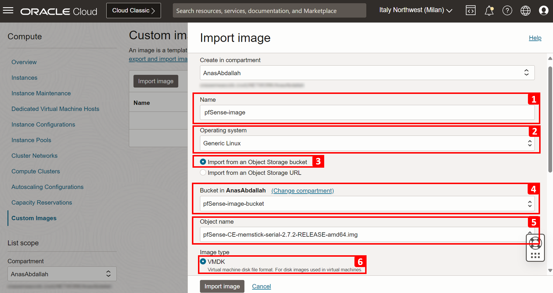
In the Import image page, enter the following information.
- Enter a Name.
- Select Generic Linux as Operating system.
- Select Import from an Object Storage bucket.
- Select the storage bucket where you uploaded the image.
- In Object name, select the object we have uploaded to the bucket (pfSense image).
- Select VMDK as Image type.
- Select Paravirtualized mode.
- Click Import image.

-
The custom image is IMPORTING.

-
After a few minutes, status is AVAILABLE

Task 3.5: Create an Instance with the Custom pfSense Image
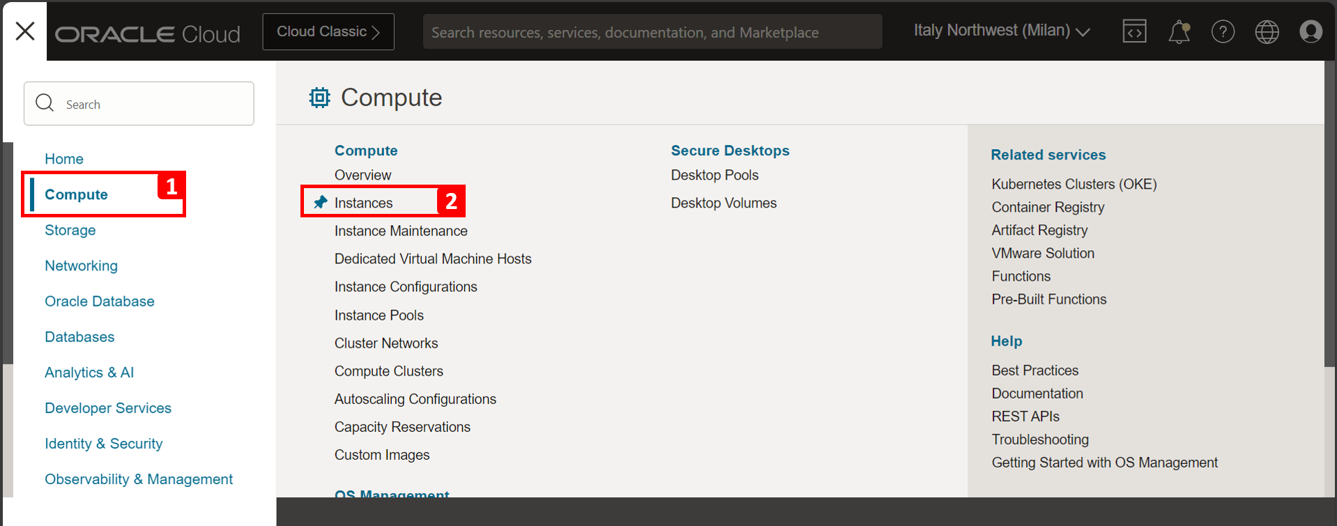
-
Click the hamburger menu (≡) from the upper left corner.

- Click Compute.
- Click Instances.
-
Click Create instance.

-
Enter a Name for the firewall instance.

- Click Change image.
- Select My images.
- Click Custom images.
- Select the custom image created in Task 3.4.
- Click Select image.
- Notice that the pfSense image is selected.


-
In Primary VNIC information section, enter the following information.
- Select Hub-VCN.
- Select the private subnet.
- Assign the instance a private IP address
10.4.0.5.


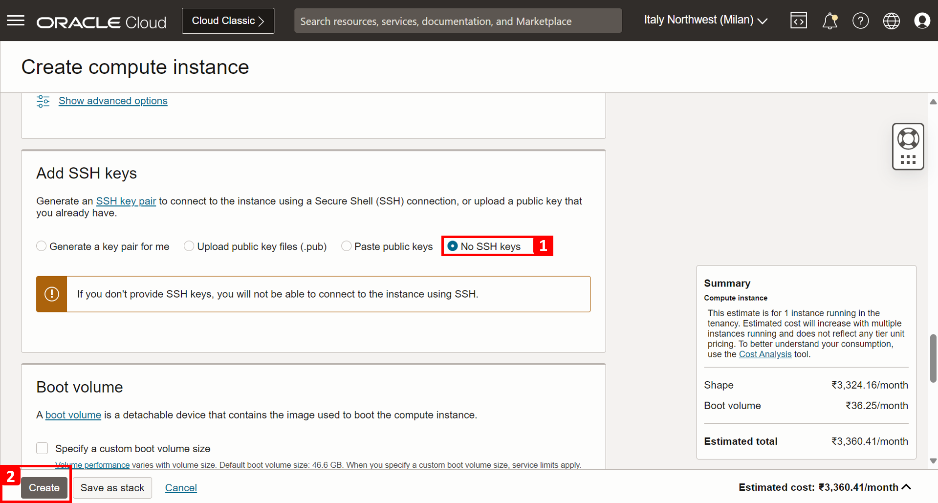
- Select No SSH Keys.
- Click Create.
-
The pfSense firewall compute instance is created successfully.

Task 3.6: Install pfSense on the Instance
We need to do the initial installation and set up of the pfSense firewall. We already have the running instance.
-
To install the pfSense firewall software, we need to create a console connection. Within the firewall instance page, scroll down.
- Click Console connection.
- Click Launch Cloud Shell connection.

-
A few startup messages will show up. Press ENTER.

-
Read the copyright messages and select Accept and press ENTER.

- Select Install pfSense.
- Select OK and press ENTER.

- Select Manual Disk Setup (experts).
- Select OK and press ENTER.

- Select da0 - 47 GB MBR.
- Select Create and press ENTER.

- In Type, enter freebsd.
- In Size, enter 46 GB.
- Enter Mountpoint.
- Select OK and press ENTER.

- In da0s4, select 46 GB BSD.
- Select Create and press ENTER.

- In Type, enter freebsd-ufs.
- In Size, enter 40 GB.
- In Mountpoint, enter /.
- Select OK and press ENTER.

- Notice that the mountpoint is created for
/. - In da0s4, enter 46 GB BSD.
- Select Create and press ENTER.

- In Type, enter freebsd-swap.
- In Size, enter 5670 MB.
- Enter Mountpoint.
- Select OK and press ENTER.

- Notice that the mountpoint is created for swap.
- Select Finish and press ENTER.

-
Select Commit and press ENTER.


-
Select Reboot and press ENTER.

-
After the first reboot you will get a few configuration options to configure the WAN interface. For Should VLANS be set up, enter n and press ENTER.

-
For Enter the WAN interface name or ‘a’ for auto-detection (vtnet0 or a), enter
vtnet0.
-
In this setup, we are creating a firewall with only one interface, so we will not configure the LAN interface, therefore, for Enter the LAN interface name or ‘a’ for auto-detection, press ENTER to skip this interface set up.

- Verify the WAN interface name.
- For Do you want to proceed, enter y and press ENTER.

-
Notice some messages and the configuration will be done. The pfSense OS will do a full boot.
- You will see that the IP address will be configured using DHCP.
- Notice the pfSense menu to do some additional basic configuration.

-
The architecture should look as shown in the following image.

Task 3.7: Connect to the pfSense Web Graphic User Interface (GUI) and Complete the Initial Set up
The installation is finished, now we need to connect to the web GUI of the pfSense firewall. But before this, make sure to allow HTTP/HTTPS traffic coming from Hub-Public-Subnet, as we will connect to the firewall GUI from the Jump-Server placed there. We already allowed all traffic from all of the VCNs (10.0.0.0/8) to go through the firewall in Task 1.2.
-
Enter pfSense firewall IP address.
- In the Windows instance, open a browser and navigate to the pfSense firewall IP using HTTPS.
- Click Advanced.

-
Click Proceed.

- Enter default username as
admin. - Enter default password as
pfsense. - Click Sign In.

- Enter default username as
-
Click Next.

-
Click Next.

- Enter a Hostname.
- Enter a Domain name or keep domain name default.
- Scroll down and click Next.

-
Click Next.

Note: The way it works in this particular case is that Oracle will reserve the static IP in its DHCP server, and will assign this address to the pfSense firewall. So the pfSense firewall will always get the same IP address, but from the OCI perspective, this will be a static IP, and from the pfSense perspective this will be a DHCP address.
- In Configure WAN interface section, Select DHCP.
- Scroll down and keep everything else as default and click Next.

- Enter a new Admin Password.
- Enter Admin Password AGAIN.
- Click Next.

-
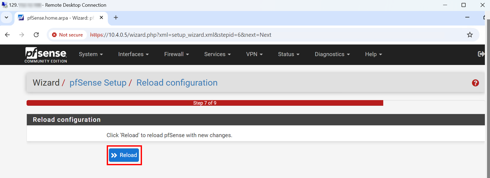
Click Reload.
-
Notice that the pfSense firewall configuration is reloading.

-
Scroll down and click Finish.

-
Click Accept.

-
Click Close.

If the pfSense firewall is not able to reach the Internet, the dashboard page will take a bit longer to load. But this can be fixed by allowing pfSense to access the Internet by using the OCI NAT gateway, which we already did in Task 1.2. In this image, notice that the pfSense is installed and the dashboard is visible.

Task 3.8: Route Traffic into the pfSense Firewall
In Task 1, we configured routing on our VCNs and DRG, in a way to force all traffic sent out of the spokes, to enter the hub network (green arrow). This task, answers how to route all of this traffic into the pfSense firewall (red arrow).

We will do this by creating an Ingress route table (Transit route table). This is basically a route table you create at the VCN level, but you assign it in the DRG, so that traffic entering the hub will be routed into a specific destination of your choice (pfSense firewall in our scenario).
-
Navigate to the pfSense firewall instance.
- Click Compute.
- Click Instances.

-
Click Firewall.

-
Scroll down.
- Click Attached VNICs.
- Click the three dots.
- Click Edit VNIC.
- Select Skip source/destination check. If you missed this step, you will face an issue when creating the route rule.
- Click Save changes.


-
Navigate to the VCNs page and enter Hub-VCN.

-
Scroll down.
- Click Route Tables.
- Click Create Route Table.
- Enter a Name for the route table.
- Click Another Route Rule.
- Select Private IP as Target Type.
- Enter
0.0.0.0/0as Destination CIDR Block. - Enter the Private IP of the pfSense.
- Click Create.
- Route table is created successfully, now we have to assign it.


-
Navigate to the DRG page and click Hub VCN Attachment.

-
Click Edit.

-
Click Show advanced options.

- Click VCN route table.
- In Associate route table, select Select existing.
- Select the route table we created.
- Click Save changes.

-
VCN route table is assigned successfully.

Note: At the DRG attachment, you can assign two types of route tables:
- DRG Route Table: The one we created for the spoke attachments in Task 1.7. This table will be checked everytime traffic is sent out of the VCN attachment.
- VCN Route Table: The one we created in this Task 3.8. This table will be checked when traffic is received and coming into the VCN attachment.
-
At this stage, we have completed all OCI-related configurations, ensuring that traffic between any two resources in this architecture is routed through pfSense for inspection first. Now, what if we did a quick test by pinging BE-VM from FE-VM, should it work?

As you observed, pfSense will block all traffic coming through until you explicitly allow it, which we are going to do in the upcoming task.
Task 3.9: Allow Traffic to pass through pfSense
In this tutorial, we are going to leverage two features of the pfSense.
-
Access Rules: Permit or deny traffic based on Protocol, Port Number, Source Address, and Destination Address.
-
Packet Capture: Apply a filter based on IP Addresses, Packet Type, Port Number and so on to analyze incoming and outgoing traffic at the packet level which the firewall will inspect.
Keep in mind that you can do a lot more with pfSense, but our focus here is more on installing pfSense in OCI and integrating it into our existing network architecture with implementing the proper routing and security in OCI.
-
In this task, we are going to allow traffic which will be needed in some of our scenarios. Since the concentration of this tutorial series is on DNS, the rules we will add will specifically relate to DNS traffic (both Native and BIND9 based). Now, navigate to the pfSense web management interface.
- Click Firewall.
- Click Rules.

-
Notice the default rules of the pfSense firewall.

First Rule (Optional):

-
Connection details.
- Source: Jump-Server (
10.4.1.5). - Destination: FE-VM (
10.1.0.5). - Protocol: SSH.
- Port Number:
22. - Action: Pass.
- Justification: We want to access FE-VM from the Jump-Server. This is an optional rule, as you can still use the bastion to connect.
- Source: Jump-Server (
-
Click Add.

- Select Action to Pass.
- Select Protocol to TCP.
- Enter Source Address to
10.4.1.5. - Enter Destination Address to
10.1.0.5. - Enter Destination Port to
22. - Click Save.
- Click Apply Changes.
- A message will appear indicating that the changes have been applied successfully.
- Rule is added.


Second Rule:

-
Connection details.
- Source: FE-VM (
10.1.0.5). - Destination: BE-VM (
10.2.0.5). - Protocol: ICMP.
- Action: Pass.
- Justification: For testing purposes, we need to enable FE-VM to ping BE-VM.
- Source: FE-VM (
-
Click Add.

- Select Action to Pass.
- Select Protocol to ICMP, and Subtype to any.
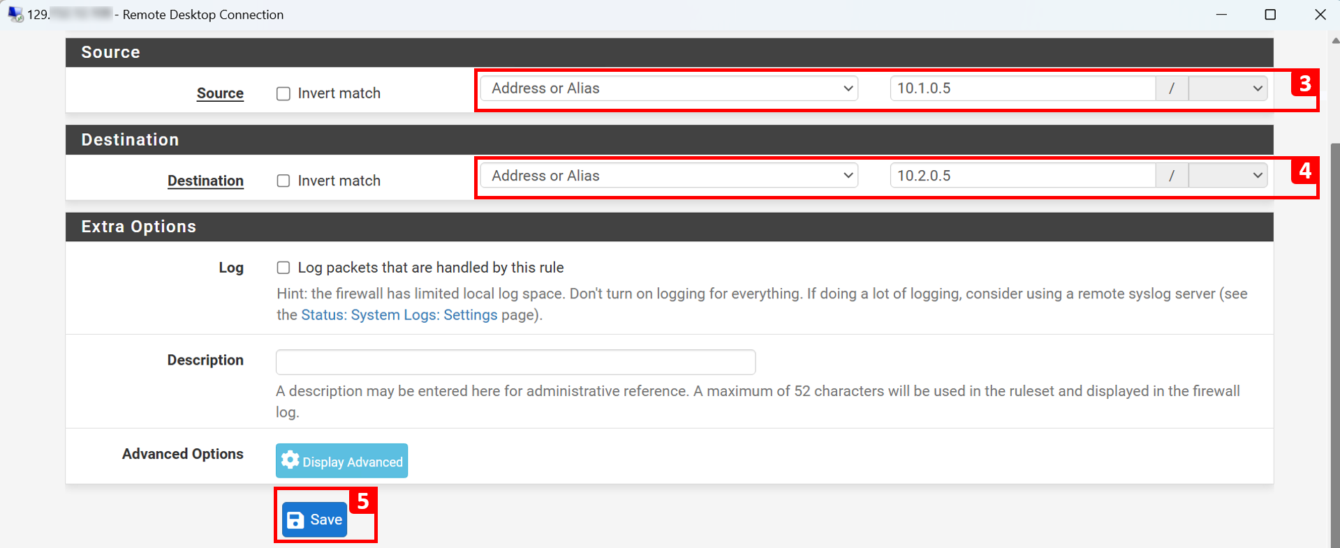
- Enter Source Address to
10.1.0.5. - Enter Destination Address to
10.2.0.5. - Click Save.
- Click Apply Changes.
- A message will appear indicating that the changes have been applied successfully.
- Rule is added.



Third Rule:

-
Connection details.
- Source: FWD of Frontend-VCN (
10.1.0.6). - Destination: LSN (
10.3.0.6). - Protocols: TCP and UDP.
- Port Number:
53. - Action: Pass.
- Justification: We want FE-VM to be able to resolve BE-VM (
be-vm.beprivatesubnet.backendvcn.oraclevcn.com). For that, FWD of Frontend-VCN must be able to query the listener. So, DNS traffic must be allowed.
- Source: FWD of Frontend-VCN (
-
Click Add.

- Select Action to Pass.
- Select Protocol to TCP/UDP.
- Enter Source Address to
10.1.0.6. - Enter Destination Address to
10.3.0.6. - Enter Destination Port to
53. - Click Save.
- Click Apply Changes.
- A message will appear indicating that the changes have been applied successfully.
- Rule is added.


Fourth Rule:

-
Connection details.
- Source: FWD of Frontend-VCN (
10.1.0.6). - Destination: DNS-NLB (
10.0.0.110). - Protocols: TCP and UDP.
- Port Number:
53. - Action: Pass.
- Justification: We want FE-VM to be able to resolve BE-VM (
be.orastage.com). For that, FWD of Frontend-VCN must be able to query the DNS-NLB which will send the traffic to one of the backend BIND9 DNS servers. So, DNS traffic must be allowed.
- Source: FWD of Frontend-VCN (
-
Click Add.

- Select Action to Pass.
- Select Protocol to TCP/UDP.
- Enter Source Address to
10.1.0.6. - Enter Destination Address to
10.0.0.110. - Enter Destination Port to
53. - Click Save.
- Click Apply Changes.
- A message will appear indicating that the changes have been applied successfully.
- Rule is added.


Fifth Rule:

-
Connection details.
- Source: FWD of Backend-VCN (
10.2.0.6). - Destination: LSN (
10.3.0.6). - Protocols: TCP and UDP.
- Port Number:
53. - Action: Pass.
- Justification: We want BE-VM to be able to resolve FE-VM (
fe-vm.feprivatesubnet.frontendvcn.oraclevcn.com). For that, FWD of Backend-VCN must be able to query the listener. So, DNS traffic must be allowed.
Note: Repeat the steps done in the Third Rule, but this time the source is different which is FWD of Backend-VCN (
10.2.0.6). - Source: FWD of Backend-VCN (
Sixth Rule:

-
Connection details.
- Source: FWD of Backend-VCN (
10.2.0.6). - Destination: DNS-NLB (
10.0.0.110). - Protocols: TCP and UDP.
- Port Number:
53. - Action: Pass.
- Justification: We want BE-VM to be able to resolve FE-VM (
fe.orastage.com). For that, FWD of Backend-VCN must be able to query the DNS-NLB which will send the traffic to one of the backend BIND9 DNS servers. So, DNS traffic must be allowed.
Note: Repeat the steps done in the Fourth Rule, but this time the source is different which is FWD of Backend-VCN (
10.2.0.6). - Source: FWD of Backend-VCN (
Task 4: Test and Validate
-
We will test only from FE-VM instance.
Note: (Optional) We are going to use the Windows Jump-Server in order to connect to FE-VM, you can still connect through bastion if that is what you prefer.
- Copy the private key we used in OCI Cloud Shell from the past tutorials into the Windows instance.
- Install OpenSSH on the server. For more information, see Technical : Install OpenSSH SFTP on Windows Server 2016.
- Run the SSH command.
- We have logged into the FE-VM instance successfully.

Test Scenario 1
-
Test native domains
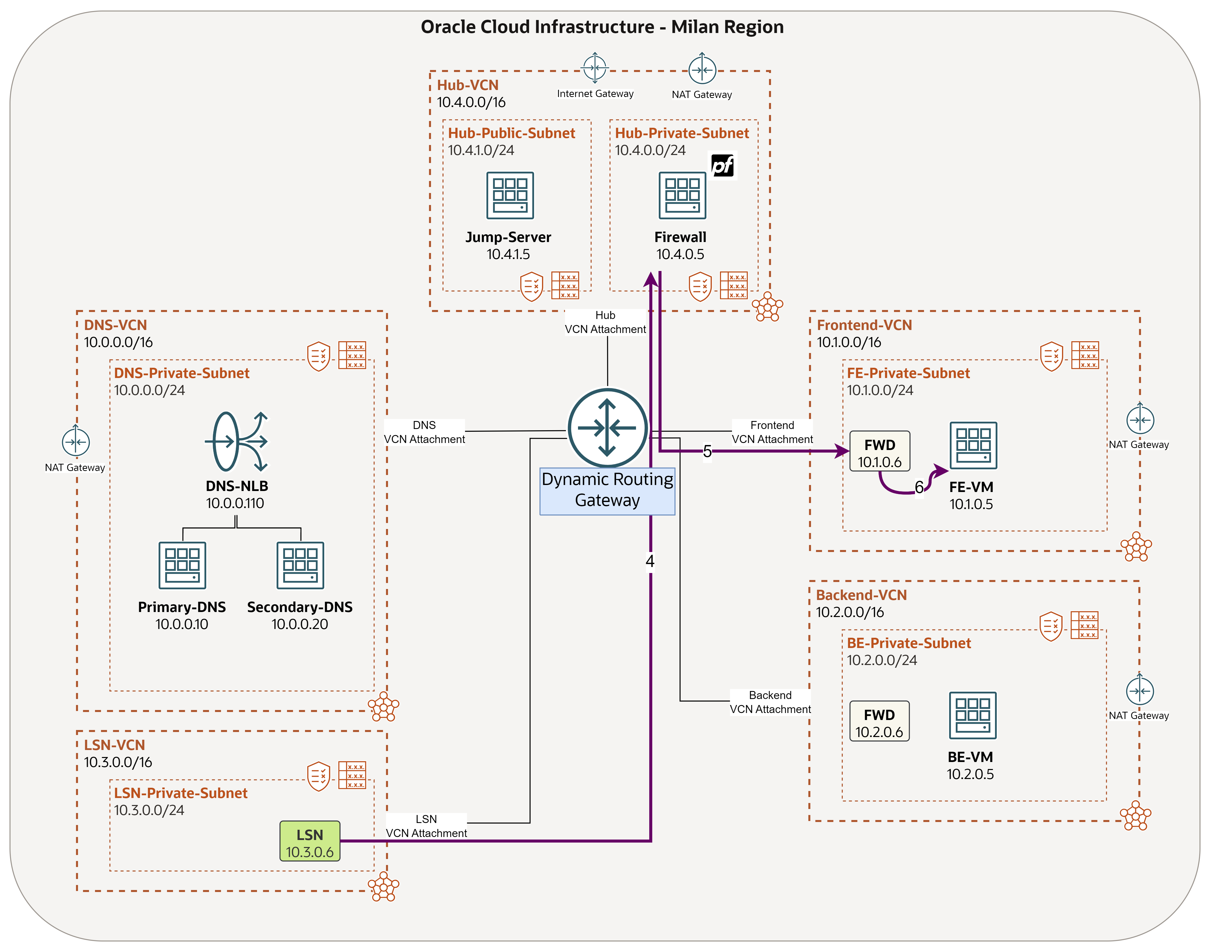
*.oraclevcn.com. The FE-VM client machine should be able to resolvebe-vm.beprivatesubnet.backendvcn.oraclevcn.com. We already allowed this traffic in pfSense. In this test, we will use the Packet Capture feature in pfSense to make sure traffic is passing through it. -
Forward Traffic:

-
Response Traffic:
-
Access pfSense from the Windows machine.
- Click Diagnostics.
- Click Packet Capture.
- Fill the Source IP (FWD - 10.1.0.6) and Destination IP (LSN - 10.3.0.6).
- Enter
53as Port Number. - Click Start.
- You can monitor DNS traffic going from FWD to LSN.


-
From FE-VM, ping BE-VM native domain
be-vm.beprivatesubnet.backendvcn.oraclevcn.com.
-
In the Packet Capture, you will notice everytime we ping it will do a query.

-
Change the filter to monitor ping traffic.
-
Forward Traffic:

-
Response Traffic:

- Fill the Source IP (FE-VM - 10.1.0.5) and Destination IP (BE-VM - 10.2.0.5).
- Enter Protocol as ICMPv4.
- Click Start.
- You can monitor ping traffic going from FE-VM to BE-VM.


-
From FE-VM, do another ping to BE-VM
be-vm.beprivatesubnet.backendvcn.oraclevcn.com.
-
In the Packet Capture, you will notice the ping traffic.

-
Scroll up and click Stop to stop the packet capture when you finish testing.

-
Click Clear Captures to start another capture.

Note: You can follow the same steps in the test but in the opposite direction, from BE-VM to FE-VM
fe-vm.feprivatesubnet.frontendvcn.oraclevcn.com. As traffic is already allowed for this scenario.
Test Scenario 2
-
Test the company’s BIND9 managed domain
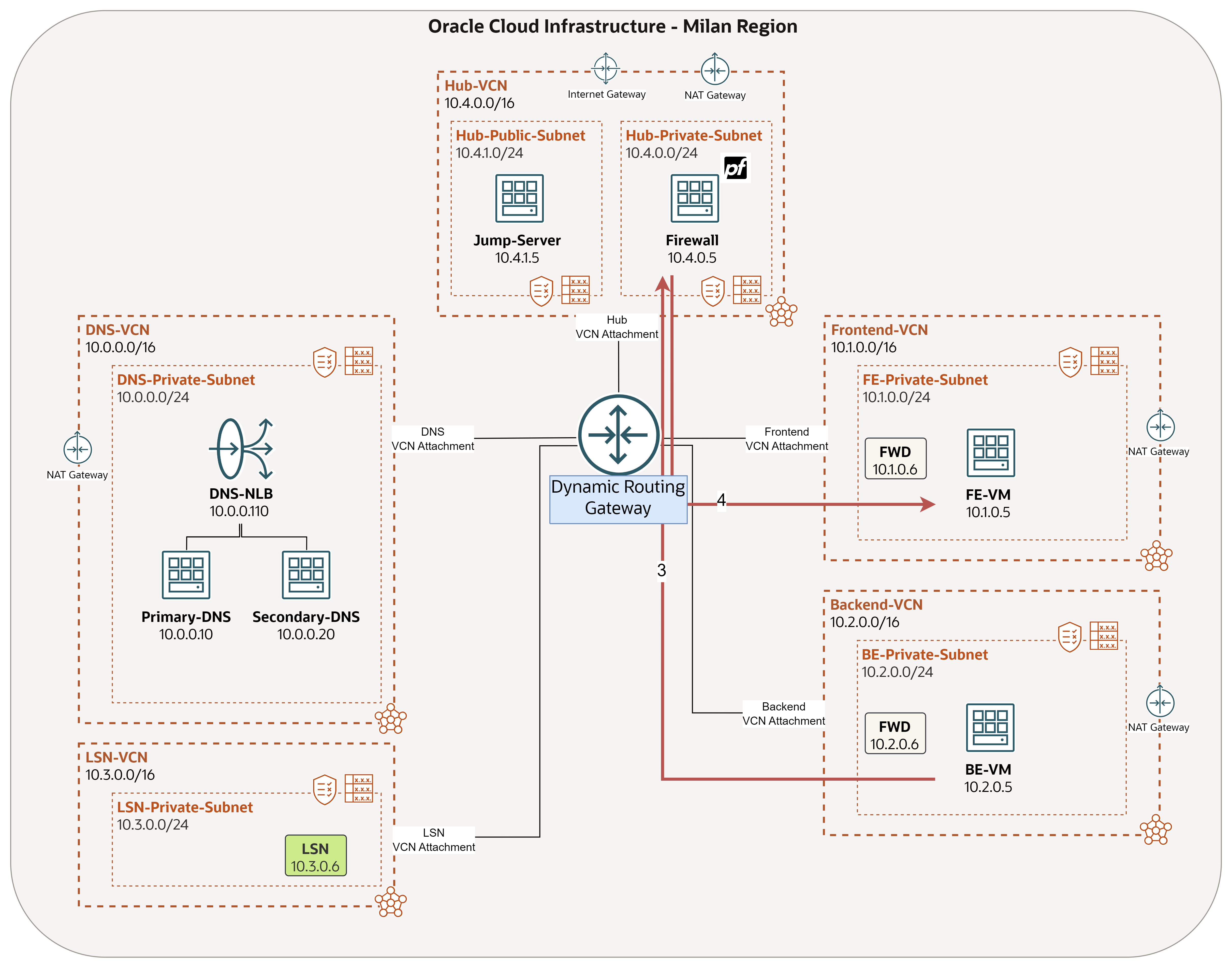
*.orastage.com. The FE-VM client machine should be able to resolvebe.orastage.com. We already allowed this traffic in pfSense. In this test, we will use the Packet Capture feature in pfSense to make sure traffic is passing through it. -
Forward Traffic:

-
Response Traffic:

-
Access pfSense from the jump server.
- Click Diagnostics.
- Click Packet Capture.
- Fill the Source IP (FWD - 10.1.0.6) and Destination IP (DNS-NLB - 10.0.0.110).
- Enter
53as Port Number. - Click Start.
- You can monitor DNS traffic going from FWD to DNS-NLB.


-
From FE-VM, ping BE-VM domain
be.orastage.com.
-
In the Packet Capture, you will notice everytime we ping it will do a query.

-
Change the filter to monitor ping traffic.
-
Forward Traffic:

-
Response Traffic:
- Fill the Source IP (FE-VM - 10.1.0.5) and Destination IP (BE-VM - 10.2.0.5).
- Enter Protocol as ICMPv4.
- Click Start.
- You can monitor ping traffic going from FE-VM to BE-VM.


-
From FE-VM, do another ping to BE-VM
be.orastage.com.
-
In the Packet Capture, you will notice the ping traffic.

-
Scroll up and click Stop to stop the packet capture when you finish testing.

-
Click Clear Captures, as we have completed the test.

Note: You can follow the same steps in the test but in the opposite direction, from BE-VM to FE-VM
fe.orastage.com. As traffic is already allowed for this scenario.
Conclusion
Congratulations! We have finally reached to the end of our DNS journey.
In this tutorial, we focused on enhancing OraStage’s DNS architecture with pfSense, which provides a crucial layer of defense against a variety of DNS-based attacks and vulnerabilities. By filtering traffic, enforcing secure DNS protocols, and blocking malicious domains, OraStage can ensure that their DNS servers operate securely and efficiently.
Throughout the series, you have picked up some important skills in OCI. Each tutorial has built on the last, giving you a solid foundation in OCI while relying on a progressive learning approach. These skills will help you manage and optimize your cloud infrastructure effectively:
- Set up Virtual Cloud Network (VCN) routing and security.
- Set up a Dynamic Routing Gateway (DRG).
- Set up and use OCI Bastion to access private instances.
- Set up and use a Windows jump server to access private instances.
- Install and configure BIND9 DNS solution in OCI.
- Configure and use OCI Network Load Balancer for high availability.
- Configure and use OCI Private DNS components to resolve native domains.
- Install and configure pfSense firewall in OCI, integrating it into a hub & spoke architecture.
Acknowledgments
- Author - Anas abdallah (Cloud Networking Specialist)
More Learning Resources
Explore other labs on docs.oracle.com/learn or access more free learning content on the Oracle Learning YouTube channel. Additionally, visit education.oracle.com/learning-explorer to become an Oracle Learning Explorer.
For product documentation, visit Oracle Help Center.
Adding Security to the Domain Name System Architecture using pfSense Firewall
G18875-02
Copyright ©2025, Oracle and/or its affiliates.