6 Servicing Power Supplies (CRU)

This section describes how to service power supplies. Power supplies are customer-replaceable units (CRUs) that do not require you to power off the server. For more information about CRUs, see Illustrated Parts Breakdown and Customer-Replaceable Units.

The power supplies are located at the back of the server. See the following procedures:

Power Supply Overview

The redundant power supply in the server supports concurrent maintenance, which enables you to remove and replace a power supply without shutting down the server, if the other power supply is online and working.

Note:

Two hot-swappable and highly-redundant 1200W A269.2 or 1400W A271 power supplies.

Two A271 1400W power supplies or two A269 1200W power supplies are included in the base configuration. Up to two power supplies are supported. Power supplies for the system are redundant (N+N) and hot-pluggable. A271 1400W power supplies require high-line 200-240 VAC sources. Mixing A271 and A269.2 power supplies within the same chassis is not supported.

The server supports model A269.2 (1200 watt) power supplies. The A269.2 power supply unit (PSU) provides conversion from the AC lines to the system, accepting ranges from 100-240 volts AC (VAC). The PSUs are hot-pluggable, and in most cases provide fully redundant “1+1” power, allowing the system to suffer the loss of a PSU or an AC feed with no loss to system availability.

In maximally configured systems, it is possible that the worst-case power consumption of the system could exceed the capacity of a single PSU. The PSUs provide an over-subscription mode (always enabled), which allows the system to operate with fault-tolerance, even with modest excursions beyond the rated capacity of a single PSU. This over-subscription support is accomplished using hardware signaling between the PSU and motherboard circuitry, which can force the system to throttle processor (CPU) and memory power in the event that a PSU is lost. The resulting power savings is enough to allow the system to continue to run (in a lower-performance state) until the power problem is resolved.

The following status indicators (LEDs) are lit when a power supply fault is detected:

  • Front and back Fault-Service Required LEDs

  • Amber Fault-Service Required LED on the faulty power supply

  • Rear Power Supply Fault-Service Required LED located on the server front panel

For more information, see Power Supply Status Indicators.

If a power supply fails and you do not have a replacement available, leave the failed power supply installed to ensure proper airflow in the server.
Remove a Power Supply

  1. Prepare the system for power supply removal.
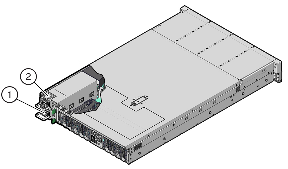
  2. Identify which power supply requires replacement.

    Figure identifying PS0, PS1, and their latches.
    Callout Description

    1

    Power supply 0

    2

    Power supply 1

    A lit amber Fault-Service Required LED on a power supply indicates that a failure was detected. You also can use the Oracle ILOM show faulty command at the Oracle ILOM command-line prompt (->) to identify a power supply failure.

    Alternatively, to list all known faults in the server, log in to Oracle Solaris and issue the fmadm faulty command (Solaris root privileges required), or log in to the Oracle ILOM Fault Management Shell from the Oracle ILOM service processor and issue the fmadm faulty command. For more information about how to use the Oracle ILOM Fault Management Shell and supported commands, refer to the Oracle ILOM User's Guide for System Monitoring and Diagnostics Firmware Release 5.0.x at Oracle Integrated Lights Out Manager (ILOM) 5.0 Documentation.

    Note:

    The fans of a failed power supply still might be spinning when the system is powered on. You can remove a power supply while the fans are still spinning.
  3. Gain access to the rear of the server where the failed power supply is located.
  4. If the cable management arm (CMA) is installed, disconnect both CMA left-side connectors and move the CMA out of the way.

    Refer to Remove the Cable Management Arm in Oracle Servers X9-2 and X9-2L Installation Guide at Oracle Server X9-2L Documentation.

    Caution:

    When disconnecting the CMA left-side connectors, be sure to use your arm to support the CMA so that it does not hang down under its own weight and stress the right-side connectors; otherwise, the CMA might get damaged. You must continue to support the CMA until you have reconnected both left-side connectors.
  5. Disconnect the power cord from the failed power supply.
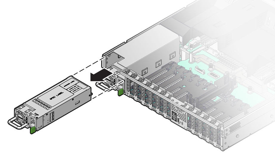
  6. Grasp the power supply handle and push the power supply latch to the left.

    Figure showing a power supply being removed from the chassis.
  7. Pull the power supply out of the chassis.

    Caution:

    When you remove a power supply, be sure to replace it with another power supply; otherwise, the server might overheat due to improper airflow.
  8. Continue to Install a Power Supply.

Install a Power Supply

Caution:

Always replace the failed power supply with the same type model of power supply.
  1. Remove the replacement power supply from its packaging, and place it on an antistatic mat.
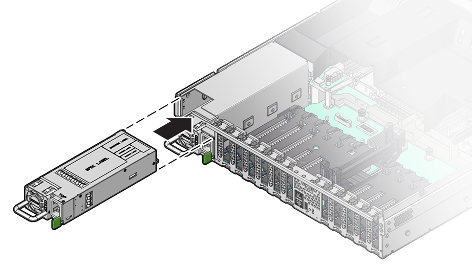
  2. Align the replacement power supply with the empty power supply slot.
  3. Slide the power supply into the slot until it is fully seated.

    You will hear an audible click when the power supply fully seats.


    Figure showing a power supply being installed into the chassis.
  4. Reconnect the power cord to the power supply.
  5. Verify that the amber Fault-Service Required LED on the replaced power supply and the Fault-Service Required LEDs are not lit on the front and back panels.

    Note:

    After you replace Power Supply 0, you must reset the Oracle ILOM service processor (SP) to propagate the key identity properties (KIP) data to the new power supply. For instructions on resetting the SP, refer to the Oracle Integrated Lights Out Manager (ILOM) 5.0 Configuration and Maintenance Guide Firmware Release 5.0.x at Oracle Integrated Lights Out Manager (ILOM) 5.0 Documentation. Power Supply 1 does not contain KIP data, and therefore does not require an SP reset after replacement.
  6. If you disconnected the two CMA left-side connectors, reconnect the connectors.

    Refer to Install the Cable Management Arm (Optional) in Oracle Servers X9-2 and X9-2L Installation Guide at Oracle Server X9-2L Documentation.