Mode Sense 6-byte (1Ah) and Mode Sense 10-byte (5Ah)
The Mode Sense commands return information about the library's operating mode parameters. The data can be truncated to the length specified in the allocation length field. The library returns a Mode Sense Parameter Header followed by one or more of the following mode pages:
- LLBA (10-byte only)
-
Set this to 0. The library will return 0 for LONGBLA in the parameter data.
- DBD (Disable Block Descriptor)
-
The library ignores this field.
- Page Control
-
0h (00b) = Current Values. The library returns the requested pages with each supported parameter set to its current value.
1h (01b) = Changeable Parameter Values. The library returns the requested pages indicating which parameters the initiator can change (1 indicates a changeable parameters and 0 indicates an unchangeable parameter).
2h (10b) = Default Values. The library returns the requested pages with each supported parameter set to its default. The default values are the same as the current values. Parameters not supported by the library are set to 0.
3h (11b) = Saved Values. This option is valid only with mode pages that can be saved. If the mode page cannot be saved, then a Check Condition is returned
- Page Code
-
HP Bridged Tape Drive:
-
02h = Protocol Specific Disconnect/Reconnect page
-
18h = Protocol Specific Logical Unit page
-
19h = Protocol Specific Port Control page
-
1Ch = Informational Exceptions TapeAlert page
-
1Dh = Element Address Assignment page
-
1Eh = Transport Geometry page
-
1Fh = Device Capabilities page
-
3Fh = All pages (in the above order)
IBM Bridged Tape Drive:
-
1Ch = Informational Exceptions TapeAlert page
-
1Dh = Element Address Assignment page
-
1Eh = Transport Geometry page
-
1Fh = Device Capabilities page
-
3Fh = All pages (in the above order)
-
- SubPage Code
-
Specifies which mode subpages are returned by the library. The supported mode subpages depend on the bridged tape drive.
HP Bridged Tape Drive: The field indicates the Serial Attached SCSI Port Control subpage, when the protocol is Serial Attached SCSI and the Page Code is set to 19h. The following subpages are supported:
01h = Serial Attached SCSI Phy Control and Discover Mode Subpage
02h = Serial Attached SCSI Shared Port Control Mode Subpage
03h = Serial Attached SCSI Enhanced Phy Control Mode Subpage
IBM Bridged Tape Drive: This field must be 00h. There are no supported mode subpages.
- Allocation Length
-
The allocation length field specifies the maximum number of bytes that the initiator has allocated for data returned from the Mode Sense command. The library transfers either the number of bytes specified by the allocation length field or all of the available mode sense data, whichever is less. The allocation length depends on the mode page and the bridged tape drive. The maximum number of bytes returned by the library is 68h (104d) bytes for Mode Sense 6 and 6Ch (108h) bytes for Mode Sense 10.
A value of 00h indicated that no mode sense data is to be transferred. This condition is not considered an error.
For Mode Sense 6-byte:
HP Bridged Tape Drive:
-
04h = Mode Sense 6 Parameter Header Length
-
08h = Mode Sense 10 Parameter Header Length
-
10h = Disconnect Reconnect Page Length
-
08h = Logical Unit Page Length
-
08h = Fibre Channel Port Control Page Length
-
10h = SAS Port Control Page Length
-
64h = SAS Phy Control and Discover Mode Subpage Length
-
0Ch = Informational Exceptions Tape Alert Mode Page Length
-
14h = Element Address Assignment Page Length
-
04h = Transport Geometry Page Length
-
14h = Device Capabilities Page Length
IBM Bridged Tape Drive:
-
04h = Mode Sense 6 Parameter Header Length
-
08h = Mode Sense 10 Parameter Header Length
-
0Ch = Informational Exceptions Tape Alert Mode Page Length
-
14h = Element Address Assignment Page Length
-
04h = Transport Geometry Page Length
-
14h = Device Capabilities Page Length
IBM Bridged Tape Drive:
-
08h = Mode Sense Parameter Header Length
-
0Ch = Informational Exceptions Tape Alert Mode Page Length
-
14h = Element Address Assignment Page Length
-
04h = Transport Geometry Page Length
-
14h = Device Capabilities Page Length
-
Mode Sense Parameter Header
Figure 2-14 Mode Sense 6-Byte Parameter Header

Description of "Figure 2-14 Mode Sense 6-Byte Parameter Header"
Figure 2-15 Mode Sense 10-Byte Parameter Header

Description of "Figure 2-15 Mode Sense 10-Byte Parameter Header"
- Mode Data Length
-
The bytes of parameter information available regardless of the allocation length. This value excludes the Mode Data Length byte, but includes three additional bytes (for Mode Sense 6-byte) or six additional bytes (for Mode Sense 10-byte) and the length of any mode pages that follow.
- Block Descriptor Length (not supported)
-
The library returns 0.
SAS Phy Control and Discover Mode Subpage
This is the same as the Mode Select SAS Phy Control and Discover Mode Subpage.
SAS Shared Control Mode Subpage
- PS (Parameters Saveable)
-
The library returns 0.
- SPF (SubPage Format)
-
The library returns a value of 1 for the SubPage Format bit, indicating this page uses the sub_page mode page format.
- Page Code
-
The value 19h identifies the page as the SAS Port Control mode page.
- Subpage Code
-
The value 02h identifies the sub-page as the SAS Shared Port Control Mode Subpage.
- Protocol Identifier
-
06h = Serial Attache SCSI protocol.
- Power Loss Timeout
-
This field contains the maximum time, in one millisecond increments, that a target port shall respond to connection requests with OPEN_REJECT (RETRY) after receiving NOTIFY (POWER LOSSEXPECTED).
The value 0000h indicates that maximum time is vendor-specific.
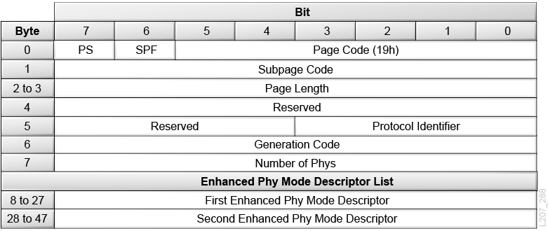
SAS Enhanced Phy Control Subpage
- PS (Parameters Saveable)
-
The library returns 0.
- SPF (SubPage Format)
-
The library returns a value of 1 for the SubPage Format bit, indicating this page uses the sub_page mode page format.
- Page Code
-
The value 19h identifies the page as the SAS Port Control mode page.
- Subpage Code
-
03h = SAS Enhanced Phy Control Mode Subpage
- Protocol Identifier
-
06h = Serial Attache SCSI protocol.
- Generation Code
-
This field is a one-byte counter that shall be incremented by one by the device server every time the values in this mode page are changed.
- Number of Phys
-
This field contains the number of phys in the SAS target device and indicates the number of Enhanced Phy Control Mode Descriptors in the Enhanced Phy Control Mode descriptor list.
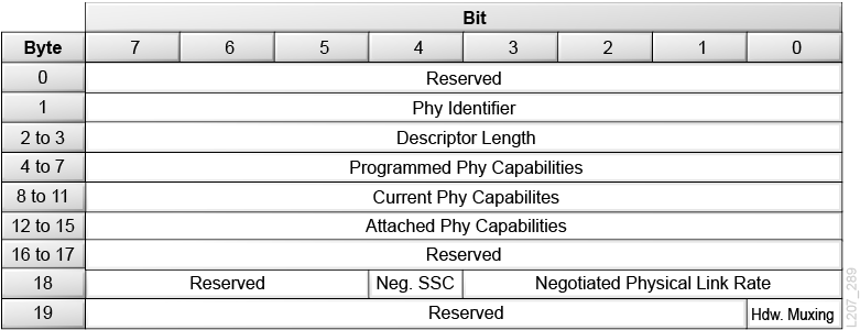
Enhanced Phy Control Mode Descriptor Data
- Phy Identifier
-
A unique Phy Identifier is returned for each Phy.
- Descriptor Length
-
The library returns a value of 10h (16d) bytes.
- Programmed, Current, and Attached Phy Capabilities
-
This field indicates the SNW-3 (Speed Negotiation Window) Phy capabilities bits that are going to be transmitted in the next link reset sequence containing SNW-3 as defined below. If the last link reset sequence did not include SNW-3, then the field will be set to 00000000h.
- Negotiated SSC
-
The Negotiated SSC bit is only valid when the Negotiated Physical Link Rate is great than or equal to 8h. When valid:
0 = SSC is enabled.
1 = SSC is disabled.
- Hardware Muxing Support
-
0 = The Phy does not support multiplexing.
1 = The Phy supports multiplexing.
Phy Capabilities Data
- TX SSC Type
-
The value 0 indicates that the phy's transmitter uses down-spreading SSC when SSC is enabled (for example, the phy is a SAS phy), or that the phy does not support SSC.
The value 1 indicates that the phy's transmitter uses center-spreading SSC when SSC is enabled (for example, the phy is an expander phy).
- Requested Logical Link Rate
-
This field indicates if the Phy device supports multiplexing and, if so, the logical link rate that the Phy device is requesting.
- G* With and Without SSC
-
0 = Does not support
1 = Supports that G level
- Parity
-
The Parity bit shall be set to one or zero such that the total number of SNW-3 Phy device capabilities bits that are set to one is even, including the Start bit and the Parity bit.
Informational Exceptions Tape Alert Control Page
This is the same as the Mode Select Information Exceptions TapeAlert Page.
Element Address Assignment Page
This is the same as the Mode Select Element Address Assignment Mode Page.
Transport Geometry Mode Page
- PS (Parameters Savable)
-
The library returns 0.
- Page Code
-
1Eh = the Transport Geometry mode page.
- Page Length
-
The number of additional types of transport geometry descriptor data to follow the header. Each descriptor has two bytes of information.
02h = The library has one transport mechanism.
- Rotate
-
0 = The library does not use multiple-sided media.
- Member Number in Transport Element Set
-
Identifies the transport element in the system.
00h = The library has one transport element.
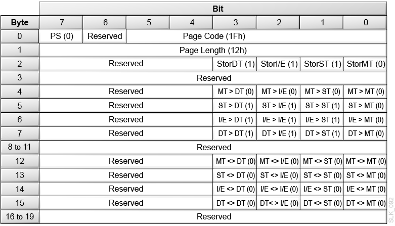
Device Capabilities Page
-
DT — Data Transfer Element (drive)
-
I/E — Import/Export Element (CAP cells)
-
ST — Storage Element (cartridge storage cell)
-
MT — Medium transport (robot hand)
- PS (Parameters Savable)
-
The library returns 0.
- Page Code
-
1Fh = The Device Capabilities mode page.
- Page Length
-
12h = 18 bytes of device capabilities data to follow.
- StorDT
-
1 = A tape drive can function as element storage.
- StorI/E
-
1 = A CAP cell can function as element storage.
- StorST
-
1 = A cartridge cell can function as element storage.
- StorMT
-
0 = The robot hand cannot function as element storage. You cannot use the robot as the source or destination of a move.
- MT > DT, MT > I/E, MT > ST, MT > MT, ST > MT, I/E > MT, DT > MT
-
0 = The robot hand (MT) cannot be the source or destination of a move.
- ST > DT, ST > I/E, ST > ST, I/E > DT, I/E > I/E, I/E > ST, DT > DT, DT > I/E, DT > ST
-
1 = Tape drives (DT), CAP cells (I/E), and cartridge cells (ST) are valid sources or destinations for a move.
- All <> Parameters
-
0 = The library does not support the exchange medium command.


