Mode Select 6-byte (15h) and Mode Select 10-byte (55h)
The Mode Select commands specify operating parameters for the library. The library uses the configuration parameters during power-on or after a logical unit reset. If you set the parameter list length field to 0, then no Mode Select data is required. Otherwise, you must provide the following mode parameter data in a parameter list:
-
A 4-byte or 8-byte Mode Select Parameter Header
-
An 8-byte Fibre Channel Logical Unit Page or SAS Logical Unit Page
-
An 8-byte Fibre Channel Port Control Page or SAS Port Control Page
-
A 12-byte Information Exceptions TapeAlert Page
-
A 20-byte Element Address Assignment Mode Page
The library accepts the Mode Select command for compatibility, but the library does not support changing Mode parameters. The library returns a check condition if a SCSI host issues a Mode Select command and attempts to change a mode page. When the library receives a Mode Select command, the library validates all parameters. If a value is invalid, the library returns an error.
- PF (Page Format)
-
Set this to 1 to indicate the page format supports the SCSI-3 specification
- SP (Saved Pages)
-
0 = Current mode values are changed to the values specified by this command. Saved values are not affected.
1 = Current mode values and saved mode values are changed to the values specified by this command.
- Parameter List Length
-
The parameter list length field specifies the length in bytes of the mode parameter list that shall be contained in the data out sent by the host. The parameter list length is the sum of the length of the mode page header and one or more mode pages.
If the parameter length results in the truncation of the mode parameter header or mode page, then the command shall be terminated with CHECK CONDITION status, with the sense key set to ILLEGAL REQUEST, and the additional sense code set to PARAMETER LIST LENGTH ERROR.
A value of 00h is not considered an error.
For Mode Select 6:
HP Bridged Tape Drive Parameter List Lengths:
-
14h = Disconnect Reconnect Page
-
0Ch = Logical Unit Page
-
0Ch = Fibre Channel Port Control Page
-
14h = SAS Port Control Page
-
68h = SAS Phy Control and Discover Mode Subpage
-
10h = Informational Exceptions Tape Alert Mode Page
-
18h = Element Address Assignment Page
IBM Bridged Tape Drive Parameter List Lengths:
-
10h = Informational Exceptions Tape Alert Mode Page
-
18h = Element Address Assignment Page
For Mode Select 10:
HP Bridged Tape Drive Parameter List Lengths:
-
18h = Disconnect Reconnect Page
-
10h = Logical Unit Page
-
0C10h = Fibre Channel Port Control Page
-
18h = SAS Port Control Page
-
6Ch = SAS Phy Control and Discover Mode Subpage
-
140h = Informational Exceptions Tape Alert Mode Page
-
1Ch = Element Address Assignment Page
IBM Bridged Tape Drive Parameter List Lengths:
-
14h = Informational Exceptions Tape Alert Mode Page
-
1Ch = Element Address Assignment Page
-
Mode Select Parameter Header
The header definitions for the library must all be 00h.
Figure 2-10 Mode Select 6-Byte Parameter Header

Description of "Figure 2-10 Mode Select 6-Byte Parameter Header"
Figure 2-11 Mode Select 10-Byte Parameter Header

Description of "Figure 2-11 Mode Select 10-Byte Parameter Header"
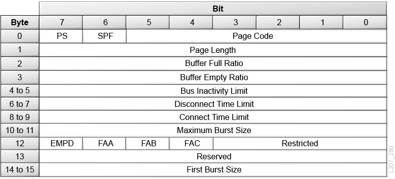
FC Disconnect/Reconnect Page
- PS (Parameters Saveable)
-
Set to 0.
- SPF (SubPage Format)
-
0 = the page_0 format is being used.
- Page Code
-
02h = Identifies the page as the Disconnect/Reconnect page
- Buffer Full Ratio
-
Indicates the device server, during read operations, how full the buffer should be prior to requesting an interconnect tenancy.
- Buffer Empty Ratio
-
Indicates the device server, during write operations, how empty the buffer should be prior to transmitting an FCP_XFER_RDY IU that requests the initiator to send data.
- Bus Inactivity Limit
-
Indicates the maximum time that the target is permitted to maintain an interconnect tenancy without data or information transfer, measured in transmission word increments.
0000h = no bus inactivity limit.
- Disconnect Time Limit
-
Indicates the minimum delay between interconnect tenancies measured in increments of 128 transmission words.
0000h = disconnect time limit does not apply.
- Connect Time Limit
-
Indicates the maximum duration of a single interconnect tenancy, measured in increments of 128 transmission words.
0000h = no connect time limit.
- Maximum Burst Size
-
Indicates the maximum size of FCP_DATA IU that the device server transfers to the initiator. This value is expressed in increments of 512 bytes.
0000h = no limit on the amount of data transferred per data transfer operation.
- EMPD (Enable Modify Data Pointers)
-
Indicates whether or not the target may use the random buffer access capability to reorder FCP_DATA IUs for a single SCSI command.
0 = Target shall generate continuously increasing relative offset values for each FCP_DATA IU for a single SCSI command.
1 = Target may transfer the FCP_DATA IUs for a single SCSI command in any order.
- FAA, FAB, FAC (Fairnes Access bits)
-
Indicate whether a target in a loop configuration shall use the access fairness algorithm. A value of 0 indicates that the target does not use fairness, while a value of 1 indicates that the target does use a fairness algorithm.
The FAA bit controls arbitration when the target wishes to send one or more FCP_DATA IU frames to an initiator.
The FAB bit controls arbitration when the initiator wishes to send one or more FCP_XFER_RDY IU frames to a target.
The FAC bit controls arbitration when the target wishes to send an FCP_RSP IU frame to an initiator.
- First Burst Size
-
0000h = no first burst size limit. This field value is expressed in increments of 512.
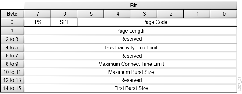
SAS Disconnect/Reconnect Page
- PS (Parameters Saveable)
-
Set to 0.
- SPF (SubPage Format)
-
0 = the page_0 format is being used.
- Page Code
-
02h = Identifies the page as the Disconnect/Reconnect page
- Bus Inactivity Time Limit
-
This field contains the maximum time in 100 µs increments that an SSP target port is permitted to maintain a connection without transferring a frame to the SSP initiator port.
0000h = no bus inactivity limit.
- Maximum Connect Time Limit
-
This field contains the maximum duration of a connection in 100 µs increments.
0000h = no connect time limit.
- Maximum Burst Size
-
For read data, this field contains the maximum amount of data in 512-byte increments that is transferred during a connection by an SSP target port per I_T_L_Q nexus without transferring at least one frame for a different I_T_L_Q nexus.
For write data, the value shall specify the maximum amount of data that an SSP target port requests via a single XFER_RDY frame.
0000h in this field specifies that there is no maximum burst size.
- First Burst Size
-
If the ENABLE FIRST BURST bit in the COMMAND frame is set to zero, then the FIRST BURST SIZE field is ignored.
If the ENABLE FIRST BURST bit in the COMMAND frame is set to one, then the value in the FIRST BURST SIZE field contains the maximum amount of write data in 512-byte increments that may be sent by the SSP initiator port to the SSP target port without having to receive an XFER_RDY frame from the SSP target port.
Fibre Channel Logical Unit Page
- PS (Parameters Savable)
-
The library sets this to 0.
- SPF (SubPage Format)
-
The library sets this to 0 to indicate page_0 format.
- Protocol Identifier
-
0h = FC protocol.
- EPDC (Enable Precise Delivery Checking)
-
0 = The target shall not use the precise delivery function and shall ignore the contents of the CRN field
1 = The logical unit shall use precise delivery function defined in the FCP-2 standard.
Fibre Channel Port Control Page
- PS (Parameters Savable)
-
The library sets this to 0.
- SPF (SubPage Format)
-
0 = page_0 format.
- Protocol Identifier
-
0h = FC protocol.
- DTFD (Disable Target Fabric Discovery)
-
If the library is not attached to an arbitrated loop, it will ignore the DTFD bit.
0 = The target attached by an arbitrated loop shall discover a fabric loop port if present on the loop and perform the public loop functions defined for targets by FC-FLA.
1 = The target attached by an arbitrated loop shall not recognize the presence of a fabric loop port on the loop.
- PLPB (Prevent Loop Port Bypass)
-
If the library is not attached to an arbitrated loop, it will ignore the PLPB bit.
0 = The target allows the Loop Port Bypass (LPB) and Loop Port Enable (PBE) primitive sequences to control the port bypass circuit and participation on the loop as specified by FC-AL-2.
1 = The target attached to an FC-AL-2 loop shall ignore any Loop Port Bypass (LPB) and Loop Port Enable (LPE) primitive sequences.
- DDIS (Disable Discovery)
-
If the library is not attached to an arbitrated loop, it will ignore the DDIS bit.
0 = The target shall wait to complete target discovery as defined by FC-PLDA, FC-FLA, and FC-TAPE before allowing processing of tasks to resume.
1 = The target without a valid FLOGI attached to an arbitrated loop will not require receipt of Address or Port Discovery (ADISC or PDISC ELSs) following loop initialization as described in FC-PLDA and FC-FLA.
- DLM (Disable Loop Master)
-
If the library is not attached to an arbitrated loop, it will ignore the DLM bit.
0 = The target may participate in loop master arbitration in the normal manner and, if successful, may become loop master during the loop initialization process.
1 = The target attached to an FC-AL-2 loop shall not participate in loop master arbitration and shall not become loop master. The target shall only repeat LISM frames it receives.
- RHA (Require Hard Address)
-
If the library is not attached to an arbitrated loop, it will ignore the RHA bit.
0 = The target follows the normal initialization procedure, including the possibility of obtaining a soft address during the loop initialization process.
1 = The target attached to an arbitrated loop shall only attempt to obtain its hard address. If there is a conflict for the hard address selection during loop initialization or the target does not have a valid hard address available, the target shall enter the nonparticipating state.
- ALWI (Allow Login without Loop Initialization)
-
If the library is not attached to an arbitrated loop, it will ignore the ALWI bit.
0 = The target shall perform the normal loop initialization procedure before entering the monitoring mode and accepting a login ELS.
1 = The target attached to an FC-AL-2 loop shall use the hard address available in the connector or in device address jumpers, enter the monitoring state in participating mode, and accept logins without using the loop initialization procedure (see FC-AL-2).
- DTIPE (Disable Target Initiated Port Enable)
-
If the library is not attached to an arbitrated loop, it will ignore the DTIPE bit.
0 = The target shall enable itself onto the loop in accordance to the rules specified in FC-AL-2.
1 = The target attached to an arbitrated loop shall wait for an initiator to send the Loop Port Enable (LPE) primitive sequence before inserting itself into a loop (see FC-AL-2)
- DTOLI (Disable Target Originated Loop Initialization)
-
If the library is not attached to an arbitrated loop, it will ignore the DTOLI bit.
0 = The target attached by an arbitrated loop shall generate LIP(F7,xx) after it enables a port into a loop.
1 = The target attached by an arbitrated loop shall not generate a LIP following insertion into the loop.
- RR_TOV Units (Resource Recovery Timeout Units)
-
011b = 0.1 second units.
- RR_TOV Values (Resource Recovery Timeout Value)
-
F0h = 24 seconds.
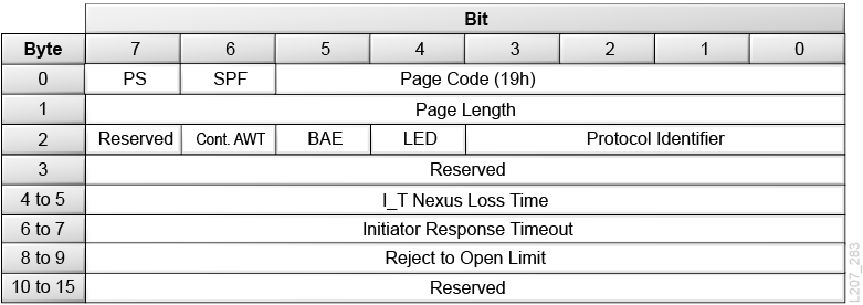
SAS Port Control Page
- PS (Parameters Savable)
-
The library sets this to 0.
- SPF (SubPage Format)
-
0 = page_0 format.
- Page Code
-
19h = SAS Port Control mode page.
- Protocol Identifier
-
06h = Serial Attache SCSI protocol
- Cont. AWT (Continuous Arbitration Wait Time)
-
0 = The SAS port shall stop the AWT timer and set the AWT timer to zero when it receives an OPEN_REJECT (RETRY).
1 = The SAS port shall not stop the AWT timer and shall not set the AWT timer to zero when the SAS port receives an OPEN_REJECT (RETRY).
- BAE (Broadcast Asynchronous Event)
-
0 = Disable origination of Broadcast (Asynchronous Event).
1 = Enable origination of Broadcast (Asynchronous Event).
- Ready LED Meaning
-
The Ready LED Meaning bit specifies the READY LED signal behavior.
- I_T Nexus Loss Time
-
This field contains the minimum time that the SSP Target Port shall retry connection requests to an SSP initiator port that are rejected with responses indicating the SSP initiator port may no longer be present before recognizing an I_T nexus loss:
0000h = Vendor-specific amount of time.
0001h - FFFFh = Time in milliseconds.
FFFFh = The SSP target port shall never recognize an I_T nexus loss.
- Initiator Response Timeout
-
This field contains the minimum time in milliseconds that the SSP target port shall wait for the receipt of a frame before aborting the command associated with that frame.
0000h indicates that the SSP target port shall wait forever.
- Reject to Open Limit
-
This field contains the minimum time in 10 microsecond increments that the target port shall wait to establish a connection request with an initiator port on an I_T nexus after receiving an OPEN_REJECT (RETRY), OPEN_REJECT (RESERVED CONTINUE 0), or OPEN_REJECT (RESERVED CONTINUE 1).
0000h indicates that minimum time is vendor specific.
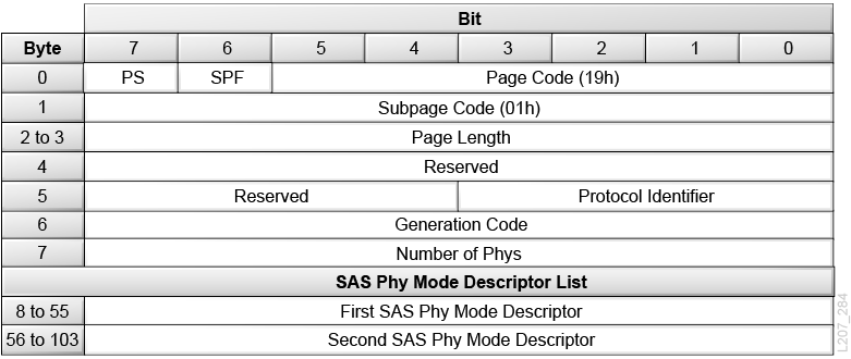
SAS Phy Control and Discover Mode Subpage
- PS (Parameters Savable)
-
The library sets this to 0.
- SPF (SubPage Format)
-
0 = page_0 format.
- Page Code
-
19h = SAS Port Control mode page.
- SubPage Code
-
01h = SAS Phy Control and Discover Mode Subpage
- Protocol Identifier
-
06h = Serial Attache SCSI protocol
- Generation Code
-
This field is a one-byte counter that shall be incremented by one by the device server every time the values in this mode page are changed.
- Number of Phy
-
This field contains the number of phys in the SAS target device and indicates the number of SAS Phy Mode Descriptors in the SAS Phy Mode descriptor list.
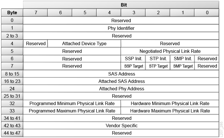
SAS Phy Mode Descriptor Data
- PS (Parameters Savable)
-
The library sets this to 0.
- Phy Identifier
-
A unique identifier is returned for each Phy.
- Attached Device Type
-
000b = No device attached
001b = SAS device
010b = Expander device
011b = Expander device compliant with a previous version of the SAS standard
- Negotiated Physical Link Rate
-
0h = UNKNOWN. Phy is enabled. Unknown Physical link rate.
1h = DISABLED. Phy is disabled.
2h = PHY_RESET_PROBLEM
3h = SPINUP_HOLD
4h = PORT_SELECTOR
8h = G1. Physical link rate is 1.5 Gb/s
9h = G2. Physical link rate is 3.0 Gb/s
Ah =G3. Physical link rate is 6.0 Gb/s
- Attached SSP, STP, SMP, SSP, STP, and SMP Initiator Port
-
This bit indicates the value of the Initiator Port field received in the IDENTIFY address frame during the identification sequence.
- SAS Address
-
The SAS Address of the drive that is the bridged interface for the library or partition.
- Attached SAS Address
-
The SAS Address field transmitted in the IDENTIFY address frame during the identification sequence.
- Attached Phy Address
-
The Attached Phy Address received in the IDENTIFY address frame during the identification sequence.
- Link Rate
-
8h = 1.5 Gb/s
9h = 3.0 Gb/s
Ah = 6.0 Gb/s
Information Exceptions TapeAlert Page
- PS (Parameters Savable)
-
The library sets this to 0.
- SPF (SubPage Format)
-
0 = page_0 format.
- Perf
-
Performance bit is set to 0, which indicates acceptance of informational exception operations that cause delays.
- EBF
-
Enable Background Functions bit will always be 0.
- EWasc
-
This should be set to 0 for the enable warning bit, indicating warning reporting shall be disabled.
- DExcpt
-
The library accepts a value of 1, which indicates the target Disables All Information Exception operations and ignores the MRIE field. In this mode, the software must poll the TapeAlert Log page.
- Test
-
0 = The library does not generate false/test informational exceptions.
1 = The library generates false/test informational exception conditions.
- LogErr
-
The Log Error information exception conditions is set to 0, which indicates this is vendor-specific.
- MRIE
-
Method the library uses to Report Informational Exceptions must be 3h, which indicates that the library reports any informational exception conditions by returning Check Condition status.
- Interval Timer
-
Bytes 4 through 7 must be 00h. The library will only report informational exception condition one time.
- Report Counter/Test Flag Number
-
This is a dual purpose field:
When the Test Flag bit is 0, this field is the report counter. Bytes 8 through 11 must be set to 00h to indicate there is no limit to the number of times the library will report the informational exception condition. This value is returned with Mode Sense.
When the Test bit is 1, this field is the test flag number.
Test Modes
Two test mode options are supported in the current TapeAlert implementation.
Test Mode for All Bits Supported
Using the mode select command to initiate this test will set all of the flags supported by the TapeAlert implementation in the TapeAlert log page. The TapeAlert log sense page then can be read to give the host a snapshot of the supported flags.
The flags will be cleared when the page is read. To do this, set the test mode flag in the TapeAlert mode select page. This indicates that the Report Count/Test Flag Number field is in Test Flag Number mode. Next, set the test flag number to 0x7FFF and issue the Mode Select command. When the command is complete, the TapeAlert log sense page can be read.
Test Mode for Individual Bits
Another test mode allows individual bits to be turned on. This can be useful for the host to debug/test operator interfaces.
Any flag set must be a supported flag. If the flag is not supported, a check condition with an incorrect parameter code is returned. The TapeAlert log sense page then can be read to allow the host to get a log page with the flag of interest set. The flag will be cleared when the page is read.
To test a flag, set the Test Flag in the TapeAlert mode select page. This indicates that the Report Count/Test Flag Number field is in Test Flag mode. Set the number of the flag to be tested. Issue the Mode Select command. When the command is complete, the TapeAlert log sense page can be read.
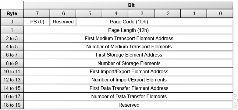
Element Address Assignment Mode Page
The library does not support changing Element Addresses. A check condition will be returned if the SCSI host issues a Mode Select command and attempts to change parameters in this page.
- PS (Parameters Savable)
-
Set to 0.
- Page Code
-
1Dh = Element Address Assignment mode page.
- Parameter Length
-
12h = 18d bytes of parameter data following this byte
- First Medium Transport Element Address
-
0000h = The address of the robot in the library.
- Number of Medium Transport Elements
-
Identifies the number of hands in the library.
The library has only one hand, so this field must be 0001h (1d).
- First Storage Element Address
-
03E8h (1000d) = The address of the first data cartridge cell in the library or partition.
- Number of Storage Elements
-
The number of data cartridge cells in the library or partition. This number depends on the configuration of the library or partition. The number must be the same number returned by Mode Sense. To obtain this value, use Mode Sense of mode page 1Dh.
- First Import/Export Element Address
-
000Ah (10d) = The address of the first mailslot in the library or partition.
- Number of Import/Export Elements
-
The number of mailslots in the library or partition. This number depends on the configuration of the library or partition. The number must be the same number returned by Mode Sense. To obtain this value, use Mode Sense of mode page 1Dh.
- First Data Transfer Element Address
-
01F4h (500d) = The address of the first drive or empty drive slot in the library or partition. If the Address All Drive Slots option is set, then the first Data Transfer Element Address may be an empty drive slot.
- Number of Data Transfer Elements
-
The number of drives and empty drive slots in the library. This number depends on the configuration of the library. The number must be the same number returned by Mode Sense. To obtain this value, use Mode Sense of mode page 1Dh.
Element Address Assignments
An initiator can modify the element addresses in the library using a Mode Select command. The four element types are:
-
Medium transport (the hand)
-
Storage element (storage cells)
-
Import/export (mailslot cells)
-
Data transfer (tape drives)
Each element type is defined as a range of consecutive elements based on a starting element and a count. The ranges may be configured in any order, but one element type range may not overlap another element type range, and gaps between ranges are allowed.
To change the element address assignments, an initiator should first perform a Mode Sense of mode page 1Dh (Element Address Assignment Page). This provides the count of each element type. The count of each element type cannot be changed and must be used as obtained from the Mode Sense command. Only the starting element number can be modified. The initiator must calculate the starting addresses of each type to ensure no overlaps.
Because the library supports the saved page function, the element address assignments can be saved in non-volatile memory. These values are used to configure the library during power-on and after a logical unit reset.


