Chapter 5 Understanding Networks
- 5.1 Networking Terminology
- 5.2 How are Networks Used in Oracle VM?
- 5.3 How are IP Addresses Assigned?
- 5.4 How is Network Bonding Used in Oracle VM?
- 5.5 How are VLANs Used in Oracle VM?
- 5.6 How are Network Functions Separated in Oracle VM?
- 5.7 Network Planning for an Oracle VM Deployment
- 5.8 Dealing with Failed Network Operations
Networking is a very broad concept with many different interpretations. Data center administrators typically have their own idea about what the best network configuration is in terms of performance, security and cost-effectiveness. In some cases physical network connections are readily available so bonding or data link aggregation is preferred for fail over or higher bandwidth, while other configurations use VLANs for network segregation or to compensate for the lack of free NICs. Some will use Ethernet connections for storage while others have dedicated fibre channel hardware at their disposal.
Generally speaking, data center operators tend to think essentially in terms of hardware: switches, routers, firewalls, cables, NICs (Network Interface Cards), and so on. The only widespread network virtualization concept to date is VLAN (Virtual LAN) technology. VLANs are also very frequently used in Oracle VM networking.
The networking infrastructure in the Oracle VM environment comprises connections between various components:
-
Between Oracle VM Servers themselves.
-
Between Oracle VM Servers and Oracle VM Manager.
-
Between Oracle VM Servers and their storage sub-systems.
-
Between virtual machines deployed in the environment.
-
Between virtual machines and external private or public networks.
These networking connections can leverage features supported by Oracle VM, such as networked file systems, clustering, redundancy and load balancing, bridging, and support for Virtual LANs (VLANs).
This chapter discusses common networking concepts used within Oracle VM and provides an overview of how and where different networking technology is used. A brief overview of some of these networking concepts is provided in Section 2.6.2, “Networking”.
For quick reference to some of the networking terminology used, refer to Section 5.1, “Networking Terminology”.
For a more thorough overview of how networks are used in Oracle VM, see Section 5.2, “How are Networks Used in Oracle VM?”.
Networking technologies such as data link aggregation or bonding are discussed in Section 5.4, “How is Network Bonding Used in Oracle VM?”, while VLANs are discussed in Section 5.5, “How are VLANs Used in Oracle VM?”.
The way in which network traffic specific to Oracle VM is assigned to different networks is described in detail in Section 5.6, “How are Network Functions Separated in Oracle VM?”.
This chapter also provides some network preparation guidelines in Section 5.7, “Network Planning for an Oracle VM Deployment”.
You may also want to review additional Oracle VM 3 Networking technical papers available on OTN at:
http://www.oracle.com/technetwork/server-storage/vm/overview/index.html
5.1 Networking Terminology
Since this chapter contains a lot of information about different networking components and their relationships, this section provides a breakdown of some of the networking terminology used here.
-
Port: the network interface on a server. This term is used interchangeably with NIC (Network Interface Card). Network ports can be used to host multiple VLAN interfaces. Multiple network ports can be bonded together for redundancy and performance reasons.
-
Bond: An aggregation of network ports that act as a single network interface for redundancy and performance reasons. Network bonding is also called Data Link Aggregation. Once a port is part of a bond, it can no longer be used outside of the bond. Oracle VM supports a number of different bonding modes or types. A bond can host multiple VLAN interfaces, or be used as an alternative to a physically cabled port.
-
Bridge: A method of conjoining different networks together to act as a single network. This technology is only used when creating Virtual Machine networks, and configuration is handled automatically within Oracle VM. Using bridges, virtual machines on one Oracle VM Server are able to communicate with virtual machines on another Oracle VM Server across a network that has been configured for this purpose.
-
VLAN: A method used to virtualize networking at the switch or router for better control over network separation. VLANs are virtual networks that use identifiers to separate traffic into different networks within the switch. Using VLANs can often reduce network maintenance overhead, as network segregation can be achieved virtually, often from a remote location. Using VLANs can allow servers with a minimal number of physical ports to act as if they were using multiple ports cabled into different networks. Since VLANs can be attached to network bonds, it is possible to achieve the same level of bandwidth that could be achieved using physical cabling by bonding ports together. Although Oracle VM Server can use VLANs, the actual VLAN creation occurs on the switch or router. Network administrators create VLANs and assign VLANs to switch ports on Ethernet switches. The physical cabling from the switch to an Oracle VM Server defines which VLANs are available on the ports or bonds on the Oracle VM Server.
-
VLAN Segments (IDs): VLANs are divided into segments that are usually tagged with an ID. This allows the switch to determine how to direct traffic. VLAN segments can be thought of as separate physical networks. If a VLAN allows untagged traffic, this traffic is all dealt with as if on the same physical network. When creating a logical network within Oracle VM Manager, VLAN segments are attached to the network in the same way that you would attach a port or a bond.
-
VLAN Interfaces: Oracle VM Manager introduces the concept of a VLAN interface. To manage network traffic tagged for different VLAN IDs, a separate virtual interface can be created for each VLAN ID. When creating different logical networks in Oracle VM Manager, these VLAN interfaces can be attached to different networks to specify the type of traffic that belongs to a particular VLAN ID.
-
Logical Network: The networks referred to in Oracle VM Manager are logical networks, in the sense that they do not necessarily represent a single physical network. Since physical components can be bonded together, bridged, or come in the form of multiple VLAN segments using a single port or bond; networks created in Oracle VM Manager are mapped to all of the individual physical or virtual components that make them up. Therefore, creating a network in Oracle VM Manager is a process of aggregating the information about individual network elements that group together into a single logical network. A logical network may incorporate multiple VLANs, physical ports or bonds.
-
Network Channel: Each logical network in Oracle VM Manager can be used for a variety of functional purposes. For performance, security and stability reasons it usually makes sense to separate these functions across different logical networks. Each function is referred to as a network channel. Network channels are used to separate types of traffic to reduce the impact that they have on each other. For instance, cluster heartbeat traffic is very sensitive to latency, while virtual machine traffic should be separated from infrastructure traffic for security reasons. Any number of channels may be attached to a logical network.
-
VNIC: Virtual machines are assigned VNICs or virtual network interface cards, which are allocated faux MAC addresses. This allows each virtual machine to connect to a network. The VNICs are bridged interfaces that are connected to a logical network that has the Virtual Machine channel enabled. A VNIC is only ever assigned to a virtual machine. A virtual machine can have as many VNICs as required within the limitations posed by the virtualization method used. For instance, hardware virtualized virtual machines are able to support a limited number of VNICs, while paravirtualized virtual machines can have an unlimited number of VNICs.
-
Server Local Network: It is possible to create a virtual network that exists on a single server and does not connect to any physical interface on that server. This type of network usually connects virtual machines running on the server. Virtual machines that use a server local network cannot be migrated or moved to another server unless the server local network is removed.
-
Hybrid Network: A hybrid network is a network that makes use of VLAN segments for some servers and physical bonds or ports for other servers in the same network. Hybrid networks are typically configured on heterogeneous hardware where VLANs are used to accommodate multiple networks on servers that lack physical ports or for servers with low priority or bandwidth requirements. While hybrid networks provide some advantages, configuring a hybrid network requires complex switch configuration and presents a higher maintenance cost for the infrastructure.
5.2 How are Networks Used in Oracle VM?
Oracle VM allows you to define logical Ethernet networks by mapping information about your existing physical network infrastructure within Oracle VM Manager. Therefore, it is very important that you are clear on the physical connections that exist within your environment before you begin configuring networks within Oracle VM Manager itself.
The physical network is the collection of physical connections in Oracle VM Manager and all Oracle VM Servers, and the switches and routers that allow information to reach its destination.
A logical network in Oracle VM is built on top of these physical connections. Each physical connection is called a network port. Other names for this physical connection include network interface card, or NIC, or network interface. Oracle VM supports both 1 Gbit and 10 Gbit NICs. Structuring your logical networks depends on the number of network ports available to your Oracle VM Servers. The minimum recommended number of ports required on a single Oracle VM Server is two, although a single port can be used for test or demonstration purposes. If you have more than two ports on your Oracle VM Servers, you can design more redundancy or traffic isolation in your environment.
Traffic isolation can be achieved by defining different logical networks dedicated to particular network functions and then assigning particular network ports to each logical network. If you have a limited number of NICs available in a system, isolation can also be achieved by configuring VLANs and then assigning these to a logical network. Redundancy can be achieved by using network bonding, so that multiple NICs essentially act as a single port. Oracle VM Manager provides many of the tools that you need to configure all of this functionality, with the exception of the creation of VLANs which must actually be performed on your switch.
Oracle VM Manager allows you to define a name or alias for each logical network that you create. When you have created your networks, you connect the physical network ports to the logical networks. In the case of VLANs, you define individual VLAN interfaces for each VLAN ID and then attach these VLAN interfaces to the network as if they were physical ports. Logical networks defined in Oracle VM Manager can then be assigned different functions or channels. All network channels can either be on dedicated or shared physical networks, except for a server local network used for virtual machines only. For example, a physical network can be dedicated to Virtual Machine or Storage only, or can be used for all network channels. These different network channels are as follows:
-
Management Network
-
Cluster Heartbeat Network
-
Live Migrate Network
-
Storage Network
-
Virtual Machine Network
Each of these network channels, how they are configured and used, is discussed in detail in Section 5.6, “How are Network Functions Separated in Oracle VM?”.
All of the network elements as well as the networks that you create in Oracle VM Manager are stored as networking objects in the Oracle VM Manager database. Your Oracle VM Servers are unaware of these Oracle VM Manager network objects. Creating and managing network objects in Oracle VM Manager results in the configuration or deletion of the network devices (for example: ports, VLAN interfaces, bridges) present on Oracle VM Servers. In the case where an Oracle VM Manager database is corrupted or lost, the networking already configured on the Oracle VM Servers remains configured. This means that if preconfigured Oracle VM Servers are discovered in a new instance of Oracle VM Manager, these networking elements are also discovered, although aliases assigned to them in a previous instance of Oracle VM Manager are lost.
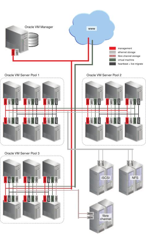
The table, titled Figure 5.1, “Oracle VM Networking Example”, shows an example of an Oracle VM environment with split network functions. Each Oracle VM Serveris connected to the management network, regardless of which server pool they belong to.
It is best practice to define separate networks for heartbeat functionality and for live migration. This is because functions like live migration can generate peaks in network traffic. Since heartbeat functionality is sensitive to peak loads, it is better that this function is not affected by a loaded network. Temporarily high network load could cause the heartbeat to fail for a server, resulting in the server being fenced out of a cluster unnecessarily. Since these types of network traffic occur at the level of an individual server pool, the networks do not need a gateway. It is important to understand that when creating different networks to handle separate functions, it is not possible for a server to belong to more than one network that has been assigned the same function.
Virtual machine traffic is often routed over a dedicated network, although it can be combined with the other network functions. In this example the dedicated virtual machine network has a route to the internet (or corporate wide area network). You can create as many virtual machine networks as permitted by your network infrastructure.
The first two server pools are connected to a storage network with Ethernet based storage providers. Ethernet based storage is provided as either NFS file servers or iSCSI LUNs. Server pool 3 has dedicated fibre channel storage, which requires a fibre channel switch and host bus adapters (HBAs) in all connected hardware components. Similar to networks for virtual machines, you create as many storage networks as needed to implement your storage strategy.
To see how you are able to create and manage different networks, see Networks in the Oracle VM Manager User's Guide.
5.3 How are IP Addresses Assigned?
When setting up a network within Oracle VM Manager you
have the option to configure the IP addressing mechanism that should be used for each
Oracle VM Server and also for each virtual machine. There
are three options, None, DHCP, and Static.
Setting the IP addressing mechanism to None leaves the IP addressing for the network
unconfigured. If you choose to make use of DHCP to automatically assign IP addresses to
servers or virtual machines within a network, you must ensure that a DHCP server is set up and
available within your Oracle VM environment. Oracle VM Manager does not function as a DHCP server
by itself. In order for DHCP to function properly, the DHCP server must be connected to the
physical network ports that you have specified for each Oracle VM Server within the network.
Furthermore, it is important that your DHCP is configured to assign static IP addresses to
interfaces on your Oracle VM Servers, since there is a requirement that the IP address for an Oracle VM Server
does not change. The behavior of the Oracle VM Server host is undefined if used in an environment
where your IP address may change due to DHCP lease expiry.
If using static IP addresses for your Oracle VM Servers or virtual machines, Oracle VM Manager automatically configures the network parameters for each Oracle VM Server or virtual machine, via the Oracle VM Agent, according to the network settings that you specify for each server or virtual machine within Oracle VM Manager.
When configuring network bridges, or networks that solely function as virtual machine networks, it is possible to not specify an IP addressing mechanism for the bridge. In this case, the bridge functions as a Layer 2 switch for the virtual machines making use of it. See Section 5.6.5.1, “Network Bridges” for more information on this.
5.4 How is Network Bonding Used in Oracle VM?
Network bonding refers to the combination of network interfaces on one host for redundancy and/or increased throughput. Redundancy is the key factor, it is desirable to protect the entire virtualized environment from loss of service due to failure of a single physical link. This network bonding is the same as the Linux network bonding or Oracle Solaris data link aggregation. Using network bonding in Oracle VM may require some switch configuration.
While Oracle VM Manager uses the Linux terminology for network bonds, Oracle Solaris users should understand this to be equivalent to data link aggregation.
In Oracle VM, there are three modes of network bonding:
-
Active Backup or Active-Passive (mode=active-backup or mode=1): There is one NIC active while another NIC is asleep. If the active NIC goes down, another NIC becomes active. While this mode does not increase throughput, it provides redundancy in case of failure. Active Backup, is a safe option if you intend use VLANs.
-
Dynamic Link Aggregation or Link Aggregation (mode=802.3ad or mode=4): Aggregated NICs act as one NIC which results in a higher throughput, but also provides failover in the case that a NIC fails. Dynamic Link Aggregation requires a switch that supports IEEE 802.3ad. Dynamic Link Aggregation is the preferred mode of network bonding, but requires that the network is configured correctly on the switch.
-
Adaptive Load Balancing or Load Balanced (mode=balance-alb or mode=6): The network traffic is equally balanced over the NICs of the machine to provide higher throughput and failover is also supported to provide redundancy. Unlike Dynamic Link Aggregation, Adaptive Load Balancing does not require any particular switch configuration.
NoteAdaptive Load Balancing or Load Balanced (mode=balance-alb or mode=6) bonding:
-
Is not currently supported for SPARC servers.
-
Is supported in x86 environments only.
-
Might not work correctly with VLAN traffic. It is not supported to have virtual machine networks on VLANs with Load Balanced bond ports.
-
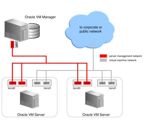
During installation of Oracle VM Server, the network interface (selected when prompted for the management port) is configured as a bonded interface. The bond is created with only one interface. This is done because the reconfiguration of the management interface on the Oracle VM Servers is not supported. You can add a second interface to the already existing bond device without affecting the configuration of the original interface. This is illustrated in Figure 5.2, “Network bonding”, where a second network interface is added to bond0, the network bond created during installation. By default, the bond mode is set to Active Backup for the management network.
Figure 5.2, “Network bonding” also illustrates the configuration of a second bonded interface, bond1, which can be used for other network usage, such as the virtual machine channel. Separation of network functions into different channels is discussed in more detail in Section 5.6, “How are Network Functions Separated in Oracle VM?”.
Note that once a network port becomes part of a bond, it becomes a slave port (secondary port). In this configuration, Oracle VM Manager is not able to actually change any configuration parameters for the secondary port. All configuration changes are applied to the bond interface. The only action that Oracle VM Manager can apply to a secondary port is to remove it from the bond. Values for some parameters, such as MTU, on the secondary port may reflect the value of the bond interface within Oracle VM Manager or when using any networking tools directly on the command line of an Oracle VM Server although only the values reflected for the bond are actually ever used. The original configuration file for the secondary port is never updated as long as it is part of the bond. This means that when a port is removed from a bond, it reverts to its original configuration and any configuration changes to parameters that applied to the bond are not applied to the released port.
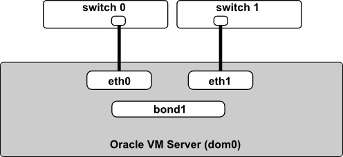
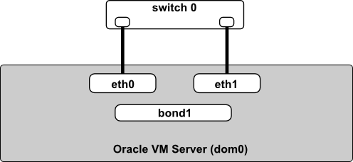
It is important to understand that the actual cabling of Ethernet interfaces is important when using network bonds. If you are using Active Backup (mode=active-backup or mode=1) or Load Balanced (mode=balance-alb or mode=6), the Ethernet ports can be connected to alternate switches as shown in Figure 5.3, “Network bonding for modes 1 and 6”. If you are using Dynamic Link Aggregation (mode=802.3ad or mode=4), the Ethernet ports can also be connected to alternate switches, but only if the switches support Virtual Switching System (VSS) or Virtual Path Channel (vPC). This is illustrated in Figure 5.4, “Network bonding for mode 4 with switch support for VSS or vPC”. If VSS or vPC is not supported for the switch you are using, the Ethernet ports must be cabled to the same switch, which is configured for dynamic link aggregation (IEEE 802.3ad). This is illustrated in Figure 5.5, “Network bonding for mode 4 with no switch support for VSS or vPC”.
If you are using Dynamic Link Aggregation (mode=802.3ad or mode=4), refer to the switch product documentation or available support channels to determine whether support for VSS or vPC is available for the switch you are using.
For more information on configuring bonds in Oracle VM, see Bond Ports Perspective in the Oracle VM Manager User's Guide.
5.5 How are VLANs Used in Oracle VM?
Oracle VM supports multiple virtual networks, or VLANs, on the same network port or bond. Each VLAN is essentially an independent logical network operating with other VLANs over the same physical connection. This means that virtual machines deployed on different networks, connected through the same Oracle VM Server port (or bond), can have traffic directed to different VLANs. This feature is implemented using VLAN Interfaces.
Configuring VLANs within Oracle VM Manager involves creating VLAN interfaces. A VLAN segment or ID is assigned to each VLAN interface when you create it. The VLAN interface is a virtual interface attached to the bond or port that physically handles the traffic for the entire VLAN. When configuring different logical networks within Oracle VM Manager, the VLAN interfaces that you have defined can be attached to the network in the same way as any ports or bonds. This allows you to treat each VLAN ID as a separate logical network interface. When traffic is routed through the VLAN interface, it is automatically tagged with the VLAN ID that is configured for that interface, and is then routed through the actual port or bond that the VLAN interface is attached to.
The VLAN ID is used by an attached VLAN switch to segregate traffic among the different VLANs operating on the same physical link. When a VLAN is configured, it functions exactly like a separate physical connection. The original physical port that the VLAN interface is attached to, can continue to be used as a separate port to route untagged traffic.
5.5.1 Configuring VLANs
You must configure the VLANs needed to support your network before you can use them. This is usually accomplished using switch trunking. Trunking involves configuring ports on the switch to allow multiple VLAN traffic on these ports, to ensure that packets are correctly transmitted to their final destination. Consult your switch vendor's documentation for information regarding trunking.
5.5.2 Configuring VLAN Interfaces
A VLAN Interface is a virtual interface that is attached to the physical network port or bond that your VLAN is configured on. The VLAN Interface is used to automatically tag traffic that is routed through it with the appropriate VLAN ID. Equally, traffic tagged with a VLAN ID that comes in on a physical port is routed through the appropriate VLAN interface. If no matching VLAN interface is found, the traffic is dropped.
You create VLAN interfaces to direct the traffic from several VLANs onto a single port or bond on each Oracle VM Server in the server pool. For example, if a port or bond is expected to carry traffic for VLAN with ID 2 and for VLAN with ID 3, you create a VLAN Interface for each of these VLAN segments. After creating the VLAN Interfaces, you create a network and specify one of the VLAN Interfaces as belonging to the network. Each packet transmitted from virtual machines on this network is tagged with the VLAN ID for the VLAN interface specified during network creation. If you added the physical network port or bond during network creation, the packets can still flow through the port or bond, but the packets are untagged. The Ethernet switch, to which the Oracle VM Servers are connected, is responsible for the transmission of packets to the appropriate VLAN.
Figure 5.6, “Networks with VLANs and VLAN Interfaces” illustrates the case of two virtual machine networks, whose network traffic flows through the same bonded interface.
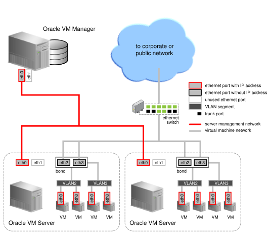
In the diagram, titled Figure 5.6, “Networks with VLANs and VLAN Interfaces”, two VLAN interfaces are defined on the bond for each server. The VLAN2 interface handles traffic tagged with the VLAN ID 2 and the VLAN3 interface handles traffic tagged with the VLAN ID 3. Two virtual machine networks have been created in Oracle VM Manager, even though these networks use the same physical network infrastructure. The first virtual machine network has the VLAN2 interface attached for each server; while the second virtual machine network has the VLAN3 interface attached for each server. For each logical network, a bridge is automatically created for the specified VLAN interface. The bridge is configured without an IP address since none is specified during configuration. Network packets from virtual machines deployed on VLAN segment 2 travel through the bridge and acquire a tag which identifies the packets as belonging to VLAN 2. Similarly, the packets issued from the virtual machines deployed on the network for VLAN segment 3 are tagged for VLAN3 with ID 3. The packets from both networks use either path to the switch if the bond is configured for Dynamic Link Aggregation. The receiving ports on the Ethernet switch are configured using trunking or similar configuration to recognize network traffic for the two VLANs in this setup. As such, the trunk ports will direct the packets to the correct VLAN on the switch, or other connected switches.
To see how you are able to create VLAN Interfaces in the Oracle VM Manager Web Interface, see VLAN Interfaces in the Oracle VM Manager User's Guide and to see how VLAN Interfaces are attached to logical networks within the Oracle VM Manager Web Interface see Networks in the Oracle VM Manager User's Guide.
5.6 How are Network Functions Separated in Oracle VM?
Depending on the number of available network ports on your Oracle VM Servers, and whether or not you use VLANs, you can create additional networks and assign network functions to them. The exception would be the Management function, which is already assigned, and cannot be removed from the management network(s) created when the Oracle VM Servers were discovered. For example, if your Oracle VM Servers have two NICs, you might create a second network with the Virtual Machine channel. Equally, networks can share functions, so you can add the Storage function to your Management network if your storage is connected to the same network as defined by the Management network.
Since it is possible that a single network can be used for multiple functions, the term used for a network function is channel. Therefore, you may want to separate different network functions into different channels. Some of these channels may share the same logical network, but ideally each channel should be assigned its own logical network.
After your management networks are in place, you can plan for the creation of other types of network. Note that once a port is selected for a particular network, it cannot be selected again when creating additional networks. You can use a combination of network bonding and VLAN Interfaces to create all the networks needed for your environment using your existing ports. Network bonding is covered in Section 5.4, “How is Network Bonding Used in Oracle VM?”; VLAN Interfaces are covered in Section 5.5, “How are VLANs Used in Oracle VM?”.
If you have more than two ports on your Oracle VM Servers, or if you are using VLANs, you can create additional networks for Storage channels. These networks might be used to connect your Oracle VM Servers to either iSCSI or NFS-based storage. Generally, all Oracle VM Servers that belong to the same pool access the same storage. For each network created, you select a port, bond or VLAN interface on each Oracle VM Server to participate in this network.
You can also create a separate network for the Live Migrate channel. After the initial server discovery, the Live Migrate channel is assigned to the Management network. Oracle VM encrypts migration traffic using SSL, to protect sensitive data from exploitation and to eliminate the requirement for a dedicated network. Nonetheless, if you have sufficient network resources on your Oracle VM Servers within a server pool, you can choose to create a separate network for live migration of virtual machines.
Similarly, the Cluster Heartbeat network channel is assigned to the Management network upon discovering the first Oracle VM Server. The heartbeat communication does not generate a lot of traffic on the network, and therefore does not have much impact on the Management network. It is however susceptible to latency. For this reason, you can choose to create a separate network for the cluster heartbeat function.
Though you can create several networks for the heartbeat and live migration functions, each Oracle VM Server can only participate in one heartbeat and live migration network.

Network configuration is independent of your server pool configuration, but both entities must be taken into account when designing your overall networking infrastructure. Oracle VM Manager communicates with all Oracle VM Servers in the environment, using the management port, independent of how Oracle VM Servers are grouped to form server pools. Some network configuration in your environment might be dependent on the storage available to specific server pools. Virtual machines deployed from separate server pools might use the same external network. For this reason, it is best to plan your network design based on current network and storage setup as well as anticipated growth.
For more information on creating a network, refer to Create New Network in the Oracle VM Manager User's Guide.
5.6.1 Management Channel
The Management channel is used to manage the physical Oracle VM Servers in a server pool, for example, to update the Oracle VM Agent on the different Oracle VM Servers. This network function is assigned to at least one network by default.
In Oracle VM the management network interface and the public interface (i.e. default route) are expected to be the same on each Oracle VM Server. Other types of network usage are allowed on the same interface, for example through the use of VLANs and/or network bridges.
The first step in configuring your Oracle VM environment is to discover your Oracle VM Servers. This step assumes that the Oracle VM Manager host and all of the Oracle VM Servers can communicate over the same network, though the Oracle VM Servers and Oracle VM Manager can reside in different subnets. When you discover the first Oracle VM Server, the management network is created automatically and takes its name from the subnet to which the Oracle VM Server is connected. Each additional Oracle VM Server discovered is either on a previously known subnet, or a new subnet. If the Oracle VM Server is on a new subnet then a new management network is constructed; if the Oracle VM Server is on a known subnet then it is simply added to that subnet. Each server in your Oracle VM environment can only have one interface designated for management, belonging to a single management network object in the Oracle VM Manager's database.
Although the Oracle VM Manager and its discovered and owned Oracle VM Servers may be on different subnets as long as they can reach each other, Network Address Translation (NAT) is not supported in this configuration. NAT would lead to a discrepancy between the actual management IP of the Oracle VM Server and the IP provided during discovery.
A network port on every Oracle VM Server is designated as the management interface during the installation of the Oracle VM Server and is configured as a bonded interface. Ports can be added to this bond or removed from it; however, you should not remove the initial port that you used to create the management interface from the bond. Once a management network is created, it can only be deleted if no servers have ports in the management network anymore.
5.6.2 Cluster Heartbeat Channel
The Cluster Heartbeat channel is used to verify if the Oracle VM Servers in a clustered server pool are up and running. The heartbeat function has a network component, where a TCP/IP communication channel is created with each Oracle VM Server. Each Oracle VM Server sends regular keep-alive packets and these packets are used to determine if each Oracle VM Server is alive.
It is recommended to separate the Cluster Heartbeat function from networks with high load, such as Storage and Live Migrate networks. If bandwidth drops too low, heartbeating connectivity might be interrupted, which could lead to rebooting of virtual machines and Oracle VM Servers.
Oracle VM uses OCFS2 as its underlying clustering file system to manage its storage repositories and provide access to shared storage.
A cluster heartbeat is an essential component in any OCFS2 cluster. It is charged with accurately designating nodes (in this case, nodes are Oracle VM Servers) as dead or alive. There are two types of heartbeats used in OCFS2:
-
The disk heartbeat where all the Oracle VM Servers in the cluster write a time stamp to the server pool file system device. See Section 3.8, “How is Storage Used for Server Pool Clustering?” for more information on this part of the clustering technology.
-
The network heartbeat which is where the Oracle VM Servers communicate through the network to signal to each other that every cluster member is alive.
The quorum is the group of Oracle VM Servers in a cluster that is allowed to operate on the shared storage. When there is a failure in the cluster, Oracle VM Servers may be split into groups that can communicate within their groups and with the shared storage, but not between groups. In this case, OCFS2 determines which group is allowed to continue and initiates fencing of the other group(s). Fencing is the act of forcefully removing an Oracle VM Server from a cluster. An Oracle VM Server with OCFS2 mounted will fence itself when it realizes that it does not have quorum in a degraded cluster. It does this so that other Oracle VM Servers are not stuck trying to access the cluster's resources. When an Oracle VM Server is fenced, it is rebooted and rejoins the cluster. If an Oracle VM Server is fenced, the virtual machines running on the fenced Oracle VM Server are migrated and restarted on other Oracle VM Servers if the virtual machines are HA enabled (virtual machines that are not HA enabled are not migrated).
The cluster heartbeat is sensitive to network interruptions and therefore the Cluster Heartbeat network should be given special attention and be treated separately to make sure that:
-
It is not sharing the same links with high traffic networks or networks that may experience sudden traffic spikes like the Storage or Live Migrate networks.
-
It has redundancy using a bond which ensures continued operation if one network path fails. See Section 5.4, “How is Network Bonding Used in Oracle VM?” for more information on configuring bonding.
5.6.3 Live Migrate Channel
The Live Migrate channel is used to migrate virtual machines from one Oracle VM Server to another in a server pool, without changing the status of the virtual machine.
While live migration should not be occurring frequently, during a live migration network traffic may spike. This could cause interruption to other services, particularly the cluster heartbeat functionality used for server pool clustering. As a result, configuring a separate network for this purpose can improve the performance and availability of other services within the environment.
5.6.4 Storage Channel
The Storage channel lets you associate specific networks with storage use. Oracle VM Manager does not enforce you to use the Storage channel for storage traffic. This channel is primarily a logical association for your information. However, when there is an attempt to remove a server port from a network that is associated with the Storage channel, Oracle VM Manager prevents the removal if there are virtual machines running on the server. This occurs to avoid errors because the virtual machine might be accessing storage on the associated network.
5.6.5 Virtual Machine Channel
The Virtual Machine channel is used for the network traffic between the different virtual machines in a server pool. The Virtual Machine channel can either be a standard inter-server network (routable through standard switches), or a server local network, an intra-server network without a route to an external physical network and dedicated to the selected Oracle VM Server. The implications of using a server local network for your Virtual Machine channel are discussed more in Section 5.7.4, “Logical Networks on a Single Oracle VM Server (local network)”.
Note that it is possible, and very likely, to have multiple networks with the Virtual Machine channel in one Oracle VM Manager.
Virtual Machine networks necessarily make use of network bridging to allow virtual machines running on different Oracle VM Servers to be able to communicate. This network bridging is discussed in more detail in Section 5.6.5.1, “Network Bridges”.
5.6.5.1 Network Bridges
When creating a network with the virtual machine channel, a bridge is created automatically on the port, bond, or VLAN interface added to the network for each Oracle VM Server participating in this network. All network packets generated by the virtual machines are sent to the bridge configured for the virtual machines' network. The bridge acts as a Layer 2 switch, and directs packets to other virtual machines running on the Oracle VM Server, or to the port or bond, if the packets' destination is outside of the Oracle VM Server.
Though each virtual machine deployed within a network is usually assigned an IP address, either static or assigned using DHCP, there is no need to configure an IP address for the bridge on the Oracle VM Servers. When configuring your Virtual Machine network, if you specify an IP address for the port, bond, or VLAN interface you selected for this network, it is assigned to the bridge. You can choose not to assign an IP address to the selected port, bond, or VLAN interface. In this case, the bridge does not acquire an address but still functions as a Layer 2 switch.
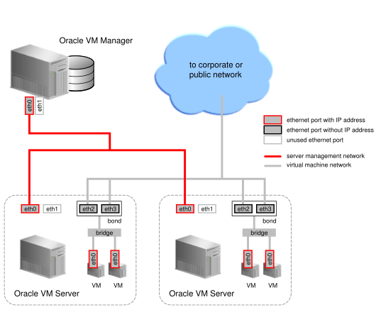
In Figure 5.8, “Network bridge”, two network ports are specified for the network with the virtual machine channel. Therefore, these ports should be configured as a bonded interface. Since this network is configured with the virtual machine channel, a bridge is automatically created on each Oracle VM Server in the network. Neither the bridge nor the ports in the virtual machine network, have IP addresses assigned to them, though you may assign IP addresses if you wish during network creation.
Bridges are only created for networks with the virtual machine channel.
5.7 Network Planning for an Oracle VM Deployment
Sufficient planning and preparation work, with regard to networking, can turn days of configuration for a large deployment into something that you can achieve in a matter of hours. In this section, we consider some of the steps that you might take to ensure that you are ready to set up networking with more ease.
The logical network constructs within Oracle VM are a combination of individual components, or building blocks. You can assemble these individual components into whatever network infrastructure you need. For this reason, during your planning phase, you should identify each component and gather the information required to map these components into virtual constructs within Oracle VM Manager. Maintaining a spreadsheet of this information can help you to prepare and properly plan for your deployment.
Before you begin, using the information provided in Section 5.6, “How are Network Functions Separated in Oracle VM?”, you should determine how much network separation you require within your deployment and what different networks you want to make use of. Remember, that in a test or demonstration environment, it is perfectly acceptable to use a single network to cater to all of your networking requirements. In a production level deployment, it is desirable to provide as much network separation as possible to ensure the best possible performance for the components that are used in an Oracle VM environment. On the other hand, depending on your networking infrastructure, the number of networks that you create may be limited by the hardware that you have at your disposal. With this in mind, prioritize the different networks based on your requirements and determine which networks may share functions.
Now identify the Oracle VM Servers that you intend to use within your deployment, along with the number of NICs available on each server. Ensure that you understand how they are cabled into your switching infrastructure. This helps to ensure that when you configure network ports in Oracle VM Manager, these ports are connected to your network infrastructure in the way that you expect. Plan how you intend to group servers into server pools.
The next part of your planning involves selecting the type of network elements that you intend to use to construct your logical networks within Oracle VM for each server pool. Logical network types consist of any of the following:
-
Networks with ports and/or bonds.
-
Networks with VLANs only.
-
Hybrid networks consisting of ports and bonds, and VLANs.
-
Logical networks on a single server (server local network).
Preparation for each network type can vary both in terms of complexity and in terms of content, since different networking components are involved in each case.
Regardless of the logical network type that you choose to use, you should bear in mind the following general networking rules:
-
By default the management network interface after an initial installation is created as a network bond called bond0. This interface can have a static or dynamic IP address, but the IP address should remain constant. It is possible to change the management interface, but this requires careful planning as the change may impact other networks used in a deployment.
-
DHCP can be used to assign IP addresses to any network interface within the deployment, however if you choose to use DHCP for the allocation of IP address information on any of the network interfaces other than the management network interface, you must ensure that a default route is not set for any interface other than the management network interface.
-
You should never configure more than one interface on the same sub-network. If you do this, the first available interface is selected for all network traffic. If you intend to use multiple network interface cards on the same sub-network, you must set up a bond.
5.7.1 Networks with Ports and/or Bonds
If you cannot support VLANs in your switches, the number of logical networks available to you is immediately limited by the number of physical NICs within each server, and whether or not you choose to make use of network bonding for redundancy and performance.
If you choose to set up network bonds on your servers, you do this as part of your server configuration process, prior to defining any additional networks within Oracle VM. Configuring network bonds using the Oracle VM Manager Web Interface is discussed in Bond Ports Perspective in the Oracle VM Manager User's Guide.
If you are only using network ports without bonding, simply keep track of how many ports are available in each server and ensure that you understand how these are connected to your switches as these ports have a one-to-one correlation with the logical networks that you are able to create. Make notes of the IP addressing and subnetworks that should be used for each port.
If you choose to use network bonding, you should identify which ports belong to which bonds you intend to create. In this case, each bond has a direct correlation with a logical network that you can create within Oracle VM. Once network bonding is enabled, the ports can no longer be used independently and your IP address and subnetwork information is specific to the network bond itself. Make notes of the IP addressing and subnetworks that should be used for each bond.
You should now be able to map the information that you have about servers, ports, bonds and IP addressing directly onto the different logical networks that you wish to create. For each logical network, make a note of the different network channels that you wish to support within each of these subnetworks. Ensure that the components that are used within the channel of the network are all physically connected to the same network.
With all of this information, you are ready to begin configuration. It is important to bear the following points in mind:
-
All servers that you wish to include in a network must have already been discovered in Oracle VM Manager
-
If you create a network with ports, these ports, located on the Oracle VM Servers that will participate in the network, cannot be part of an already existing network.
-
If you are using network bonds, you must create these on each of your servers before you begin adding networks
5.7.2 Networks with VLANs Only
If your switching infrastructure supports VLANs and you have opted to make use of them, you are able to perform traffic separation across each VLAN regardless of the number of actual physical network ports that are available within each of your servers. Nonetheless, different VLAN segments may be available on different ports or bonds that you may have already configured.
Therefore, for each server, you should list the VLAN segment IDs on each port or bond. Make a note of the IP address and subnet information for each VLAN segment. If your network traffic is routed, also include the default gateway IP address here.
Once you have a list of ports or bonds and the VLAN segments that belong to them, you have the information that you need to define your VLAN Interfaces within Oracle VM. List the VLAN Interfaces that you intend to create for each server pool. Within this list, assign each VLAN Interface to the logical networks that you intend to create. For each logical network, list the channels that the network can support. Ensure that the components that are used within each channel of the network are all physically connected to the same network and that the VLAN segments on each NIC are configured correctly on your switches.
With all of this information, you are ready to begin configuration. It is important to bear the following points in mind:
-
All servers that you wish to include in a network must have already been discovered in Oracle VM Manager
-
If you are using network bonds, you must create these on each of your servers before you begin adding networks or creating VLAN Interfaces
-
You must create VLAN Interfaces before you start adding networks
-
When creating a VLAN Interface, you provide the following information:
-
The port on the server where VLAN traffic for the VLAN ID or segment is routed.
-
The VLAN ID that the VLAN Interface should handle.
-
And, optionally, the IP address to assign to each port or VLAN interface.
Note that when actually creating VLAN Interfaces for a server, the Oracle VM Manager Web Interface provides the facility to generate multiple VLAN Interfaces for a range of VLAN IDs in a single step, reducing the amount of work involved in configuring each VLAN segment.
-
-
When creating the network do not specify any ports or bonds to add to the network. Instead, add the appropriate VLAN interfaces to the network.
5.7.3 Hybrid Networks (VLANs with Ports and Bonds)
If your servers have multiple NICs and your switching infrastructure supports VLANs, there may be some scenarios where you need to set up a hybrid network that utilizes a combination of VLANs and network bonds or ports. Consider a situation where some of the servers within a pool are connected to a switch that is configured for VLANs, while another group of servers with multiple NICs is connected to a switch that does not offer VLAN support. In this situation, a network can be created that uses the VLAN Interfaces defined for the first set of servers, but uses ports or bonds for the second set of servers.
Since these network types are using a combination of technologies, they are also the most complex to plan for and require explicit switch setup to handle adding and removing VLAN tags when crossing environments. This is a highly advanced and relatively unusual configuration. Therefore, performing adequate preparation work is essential and can help avoid confusion when you are configuring networks within Oracle VM Manager.
Maintain a list of all of the Oracle VM Servers for each server pool. Ensure that the list includes the information for each port on each server. If the server is configured to use network bonding, list the bonds and include the actual physical NICs that are part of the bond.
Group together servers that are going to use VLANs and servers that are only using ports or bonds. For the servers that are using ports or bonds, ensure that the IP address and subnet information is listed. For servers using VLANs, you should list the VLAN segment IDs on each port or bond. Make a note of the IP address and subnet information for each VLAN segment. If your network traffic is routed, also include the default gateway IP address here.
For each logical network that you intend to create, list the channels that the network can support. Ensure that the components that are used within each channel of the network are all physically connected to the same network and that the VLAN segments on each port or bond are configured correctly on your switches. Also ensure that for each server not using VLAN technology, the cabling is correct for each network port and that the components within each channel are all connected to the same network.
With all of this information, you are ready to begin configuration. It is important to bear the following points in mind:
-
All servers that you wish to include in a network must have already been discovered in Oracle VM Manager.
-
If you are using network bonds, you must create these on each of your servers before you begin adding networks or creating VLAN Interfaces.
-
You must create VLAN Interfaces before you start adding networks.
-
When creating a VLAN Interface, you provide the following information:
-
The port on the server where VLAN traffic for the VLAN ID or segment is routed.
-
The VLAN ID that the VLAN Interface should handle.
-
And, optionally, the IP address to assign to each port or VLAN interface.
Note that when actually creating VLAN Interfaces for a server, the Oracle VM Manager Web Interface provides the facility to generate multiple VLAN Interfaces for a range of VLAN IDs in a single step, reducing the amount of work involved in configuring each VLAN segment.
-
-
Ensure that servers that are not using VLAN Interfaces are added to the network and that the correct port or bond is added to the network.
-
Finally for the servers using VLAN Interfaces, add the appropriate VLAN interfaces to the network.
5.7.4 Logical Networks on a Single Oracle VM Server (local network)
You may also create a network which is intended for a single server. This type of network allows communication between the virtual machines running on a single Oracle VM Server, and does not allow external network traffic. A computing environment made up of several virtual machines, where the virtual machines provide services to each other over the network, could benefit from this type of network, without requiring additional network ports on the Oracle VM Server. As the network traffic can never leave the server, it can be a high speed network. Virtual machines using this type of network cannot be moved or migrated to another Oracle VM Server unless the network configuration is removed from the virtual machine. This is known as a server local network.
Little additional planning or preparation for server local networks is required, however if you use networks of this type, you should decide which Oracle VM Servers you intend to create them on and understand that the virtual machines running on these servers cannot be moved or migrated easily.
5.8 Dealing with Failed Network Operations
Network configuration is a complex operation involving many different elements in the physical and logical environment. Many instructions are sent to the Oracle VM Servers in the process, and if a single instruction in a whole sequence goes wrong, the resulting state of the network configuration is unpredictable. To avoid badly or partly configured network objects, which become unusable, Oracle VM Manager has a mechanism in place that is triggered when a network operation fails: a network discovery is launched for each Oracle VM Server that participated in the operation, and the commands that completed successfully are reflected in the network model displayed in the Oracle VM Manager Web Interface.
The moment a network operation fails, an event is created. In the Oracle VM Manager Web Interface this event is displayed in the Events tab of each affected Oracle VM Server. When the subsequent automatic network discovery completes, the event is also automatically acknowledged. Note that if you acknowledge the event manually, the discovery operation is not cancelled. Jobs and events are discussed in more detail in Chapter 8, Understanding Jobs, Events and Errors.
The automatic network discovery is not instantaneous. The operations start as soon as the job fails, but could take some time to finish: from a few seconds to a couple of minutes. This will depend on how complicated the network configuration is and how many Oracle VM Servers are involved.
During network discovery, resources may be locked or may change to reflect the new state of the Oracle VM Servers. To avoid resource locking issues and further failing operations, it is recommended that you wait for the discovery operation to complete before you resume the reconfiguration of the network. Check the events for each Oracle VM Server to know the status of the operation.
In case your network configuration returns a failed job, you have to manually go through all the physical and logical network elements involved and make the necessary changes one by one in Oracle VM Manager. Typical network elements include: network interfaces, Ethernet ports, bond ports, VLAN interfaces and IP addresses. The amount of manual reconfiguration depends on the complexity of your network configuration and the number of Oracle VM Servers involved.