A BPEL Process Activities and Services
This appendix describes the BPEL process activities and services that you use when designing a BPEL process in a SOA composite application. It also describes how to publish and browse the Oracle Service Registry and how the Oracle Enterprise Repository provides design-time governance.
This appendix includes the following sections:
-
Section A.4, "Publishing and Browsing the Oracle Service Registry"
-
Section A.5, "Providing Design-time Governance with the Oracle Enterprise Repository"
A.1 Introduction to Activities and Components
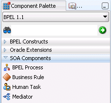
When you expand SOA Components in the Component Palette of Oracle BPEL Designer, service components are displayed. Figure A-1 shows the components that display for a BPEL 1.1 process. A BPEL 2.0 process also shows the same components.
See the following sections for additional details about these service components.
-
BPEL process
-
Business rule
-
Human task
-
Mediator
For information about Oracle BPEL Designer, see Chapter 4, "Getting Started with Oracle BPEL Process Manager."
A.2 Introduction to BPEL 1.1 and 2.0 Activities
This section provides a brief overview of BPEL activities and provides references to other documentation that describes how to use these activities.
Oracle BPEL Designer includes BPEL 1.1 and BPEL 2.0 activities that can be added to a BPEL process. These activities enable you to perform specific tasks within a process. Some activities are available in both BPEL 1.1 and BPEL 2.0. Others are available in only BPEL 1.1 or BPEL 2.0.
To access these activities, go to the Component Palette of Oracle BPEL Designer. The activities display under either of two categories:
-
BPEL Constructs: Displays core activities (also known as constructs) provided by standard BPEL 1.1 and 2.0 functionality. The activities in this category are displayed under additional subcategories of Web Service, Activities, and Structured Activities in BPEL 1.1 and Web Service, Basic Activities, and Structured Activities in BPEL 2.0.
-
Oracle Extensions: Displays extension activities that add value and ease of use to BPEL 1.1 and 2.0 functionality.
Table A-1 lists the available activities.
Table A-1 BPEL 1.1 and 2.0 Constructions and Extensions
| Activity | Display Under... | Supported in BPEL 1.1 | Supported in BPEL 2.0 | For More Information |
|---|---|---|---|---|
|
Assign |
BPEL Constructs |
Yes |
Yes |
|
|
Assert |
Oracle Extensions |
Yes |
Yes |
|
|
Bind Entity |
Oracle Extensions |
Yes |
No |
|
|
Compensate |
BPEL Constructs |
Yes |
Yes |
|
|
CompensateScope |
BPEL Constructs |
No |
Yes |
|
|
Create Entity |
Oracle Extensions |
Yes |
No |
|
|
Dehydrate |
Oracle Extensions |
Yes |
Yes |
|
|
|
Oracle Extensions |
Yes |
Yes |
|
|
Empty |
BPEL Constructs |
Yes |
Yes |
|
|
Exit |
BPEL Constructs |
No |
Yes |
|
|
Flow |
BPEL Constructs |
Yes |
Yes |
|
|
FlowN |
Oracle Extensions |
Yes |
No |
|
|
forEach |
BPEL Constructs |
No |
Yes |
|
|
If |
BPEL Constructs |
No |
Yes |
|
|
IM |
Oracle Extensions |
Yes |
Yes |
|
|
Invoke |
BPEL Constructs |
Yes |
Yes |
|
|
Java Embedding |
Oracle Extensions |
Yes |
Yes |
|
|
Partner Link |
BPEL Constructs |
Yes |
Yes |
|
|
Phase |
Oracle Extensions |
Yes |
Yes |
|
|
Pick |
BPEL Constructs |
Yes |
Yes |
|
|
Receive |
BPEL Constructs |
Yes |
Yes |
|
|
Receive Signal |
Oracle Extensions |
Yes |
Yes |
|
|
Remove Entity |
Oracle Extensions |
Yes |
No |
|
|
RepeatUntil |
BPEL Constructs |
No |
Yes |
|
|
Replay |
Oracle Extensions |
Yes |
Yes |
|
|
Reply |
BPEL Constructs |
Yes |
Yes |
|
|
Rethrow |
BPEL Constructs |
No |
Yes |
|
|
Scope |
BPEL Constructs |
Yes |
Yes |
|
|
Sequence |
BPEL Constructs |
Yes |
Yes |
|
|
Signal |
Oracle Extensions |
Yes |
Yes |
|
|
SMS |
Oracle Extensions |
Yes |
Yes |
|
|
Switch |
BPEL Constructs |
Yes |
No |
|
|
Terminate |
BPEL Constructs |
Yes |
No |
|
|
Throw |
BPEL Constructs |
Yes |
Yes |
|
|
Transform |
Oracle Extensions |
Yes |
Yes |
|
|
User Notification |
Oracle Extensions |
Yes |
Yes |
|
|
Validate |
Oracle Extensions (in BPEL 1.1) BPEL Constructs (in BPEL 2.0) |
Yes |
Yes |
|
|
Voice |
Oracle Extensions |
Yes |
Yes |
|
|
Wait |
BPEL Constructs |
Yes |
Yes |
|
|
While |
BPEL Constructs |
Yes |
Yes |
For more information about activities, see the Business Process Execution Language for Web Services Specification Version 1.1 or the Web Services Business Process Execution Language Specification Version 2.0 by visiting the following URL:
http://www.oasis-open.org
A.2.1 Tabs Common to Many Activities
While each activity performs specific tasks, many activities include tabs that enable you to perform similar tasks. This section describes these common tabs.
A.2.1.1 Annotations Tab
The Annotations tab displays on all activities and enables you to provide descriptions in activities in the form of code comments and name-and-pair value assignments.
The Annotations tab does not provide a method for changing the order of annotations. As a work around, change the order of annotations in the Source view of the project's BPEL file in Oracle BPEL Designer.
A.2.1.2 Assertions Tab
The Assertions tab displays in invoke, receive, reply, and the onMessage branches of pick and scope activities. A set of assertions are executed upon receipt of a callback message at a request-response operation in these activities. The assertions specify an XPath expression that, when evaluated to false, causes a BPEL fault to be thrown from the activity. This provides an alternative to using a potentially large number of switch, assign, and throw activities after a partner callback.
You can select when to execute a condition:
-
Preassert: This condition is executed before the invoke or reply activity send out the outbound message.
-
Postassert: This condition is executed after an invoke activity, receive activity, or onMessage branch receives the inbound message.
For more information, see the online help for this tab and Section 12.14, "Throwing Faults with Assertion Conditions."
A.2.1.3 Correlations Tab
The Correlations tab displays in invoke, receive, and reply activities, the onMessage branch of pick activities, and the OnMessage branch of scope activities. Correlation sets address complex interactions between a process and its partners by providing a method for explicitly specifying correlated groups of operations within a service instance. A set of correlation tokens is defined as a set of properties shared by all messages in the correlated group.
For more information, see the online help for this tab and Section 9.1, "Using Correlation Sets in an Asynchronous Service."
A.2.1.4 Documentation Tab
The Documentation tab enables you to embed human documentation in the activities of a BPEL file. These comments only display in the source code of the BPEL file. Example A-1 provides details.
<invoke>
. . .
   <documentation>
      Invokes the credit rating service partner link
   </documentation>
. . .
Note:
This tab is only available in BPEL 2.0 projects.A.2.1.5 Headers Tab
The Headers tab displays in invoke, receive, and reply activities, and the onMessage branch of pick and scope (for BPEL 1.1) activities. You create header variables for use with the Advanced Queuing (AQ), File, FTP, MQ, and Java Message Service (JMS) adapters.
For more information, see the online help for this tab and Oracle Fusion Middleware User's Guide for Technology Adapters
A.2.1.6 Properties Tab
The Properties tab displays in invoke, receive, and reply activities, and the onMessage branch of pick and scope activities. You can define normalized message header properties for Oracle BPEL Process Manager, Oracle Mediator, Oracle JCA adapters, and Oracle B2B.
For more information, see the online help for this tab and Appendix H, "Normalized Message Properties."
A.2.1.7 Skip Condition Tab
The Skip Condition tab displays in most activities and enables you to specify an XPath expression that, when evaluated to true, causes the activity to be skipped. This extension provides an alternative to the case pattern of a switch activity that you use to make an activity conditional.
For more information, see the online help for this tab and Section 11.5, "Specifying XPath Expressions to Bypass Activity Execution."
A.2.1.8 Source and Targets Tabs
The Sources and Targets tabs enable you to define the source and target activities to execute in a flow activity. This feature enables you to synchronize the execution of activities within a flow activity to ensure that a target activity only executes after a source activity has completed.
Note:
These tabs are only available in BPEL 2.0 projects. For BPEL 1.1 projects, you must directly edit the BPEL file to use this functionality.For more information, see the online help for this tab and Section 10.2.3, "Synchronizing the Execution of Activities in a Flow Activity."
A.2.1.9 Timeout Tab
The Timeout tab displays in receive activities and provides a timeout setting for request-response operations. This provides an alternative to the onMessage and onAlarm branches of a pick activity that you must use when you want to specify a time out duration for partner callbacks.
For more information, see the online help for this tab and Section 15.3, "Setting Timeouts for Request-Reply and In-Only Operations in Receive Activities."
A.2.2 Copying and Pasting Activities in BPEL Projects
You can copy and paste activities in the same BPEL project or between BPEL projects. This prevents you from having to create similar activities from start to finish multiple times. You can design an activity once and use it in multiple places, editing it as necessary.
Note:
You can copy an individual OnAlarm activity from one scope activity and paste it into another scope activity. You can also copy an individual OnAlarm activity from one pick activity and paste it into another pick activity.Note the following restrictions:
-
You cannot copy activities from a BPEL 1.1 project to a BPEL 2.0 project or from a BPEL 2.0 project to a BPEL 1.1 project.
-
In BPEL 2.0 projects, you cannot copy an individual OnAlarm activity from a pick activity into a scope activity, or vice versa. However, this type of copying and pasting is supported in BPEL 1.1 projects.
-
When you copy and paste a scope activity, the variables referenced in the first scope activity are not copied.
-
Right-click the activity to copy.
-
Select Copy.
-
Go to the project in which to paste the activity.
-
Perform one of the following tasks:
-
Right-click the activity closest to where you want to paste the activity.
-
Choose to either paste the activity before or after the selected activity.
or
-
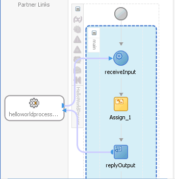
Highlight the BPEL process, as shown in Figure A-2.
-
Right-click and select Paste Into.
The activity is pasted at the top of the BPEL process.
-
A.2.3 Assign Activity
This activity provides a method for data manipulation, such as copying the contents of one variable to another. Copy operations enable you to transfer information between variables, expressions, endpoints, and other elements.
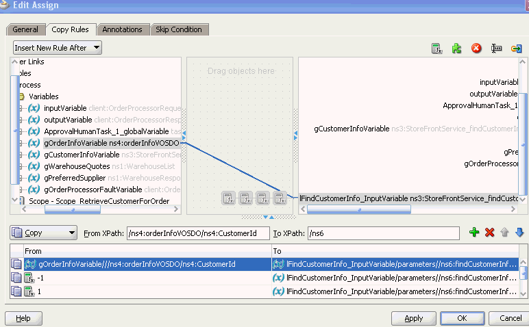
Figure A-3 shows the Copy Rules tab of the Assign dialog for BPEL 1.1. You create a mapping between source and target nodes in the tree in either of the following ways:
-
Drag the source node to the target node to create a BPEL copy rule from the source to the target node. This action creates a line that connects the source and target types.
-
Select the source node, select the target node, and then click the Add icon above the table at the bottom of the dialog. The mapping is then added to the table and the connecting line between the nodes is drawn in the tree.
The copy rule is displayed in the From and To sections at the bottom of the dialog.
Figure A-3 Copy Rules Tab of Edit Assign Dialog
Description of "Figure A-3 Copy Rules Tab of Edit Assign Dialog"
The Select Insertion Mode list above the source node section enables you to insert the next copy rule you create either after or before the rule selected at the bottom of the dialog.
Icons display above the target node that enable you to perform the following tasks (from left to right) on target nodes. By default, the center canvas is open. If it is closed, drag the bars open to display the center canvas.
-
Expression icon: Drag this icon to a target node to invoke the Expression Builder dialog for assigning an XPath expression to that node. You can also drag this icon to the center canvas to invoke this dialog, specify the expression, save and close the dialog, and then drag the icon to the target node.
-
Literal (BPEL 2.0 specification) icon or XML Fragment (BPEL 1.1 specification) icon: Drag this icon to a target node to invoke a dialog for assigning a literal (if the BPEL project supports the BPEL 2.0 specification) or XML fragment (if the BPEL project supports the BPEL 1.1 specification) to that target node. You can also drag this icon to the center canvas to invoke this dialog, specify the value, save and close the dialog, and then drag the icon to the target node.
-
Remove icon: Drag this icon to a target node to create a
bpelx:removeextension rule. You can also drag this icon to the center canvas to invoke this dialog, specify the rule, save and close the dialog, and then drag the icon to the target node. -
Rename icon: Drag this icon to rename a target node. This adds a
bpelx:renameextension rule with anelementToattribute. You can also drag this icon to the center canvas to invoke a dialog, specify the rule, save and close the dialog, and then drag the icon to the target node. -
Recast icon: Drag this icon to recast a target node. This adds a
bpelx:renameextension rule with atypeCastToattribute. This results in anxsi:typeattribute in the XML output. You can also drag this icon to the center canvas to invoke a dialog, specify the rule, save and close the dialog, and then drag the icon to the target node.
You can also change a selected copy rule to a bpelx extension type (bpelx:copyList, bpelx:insertAfter, bpelx:insertBefore, or bpelx:append).
The method of selection differs between BPEL 1.1 and BPEL 2.0.
Figure A-4 shows how you select an extension type in BPEL 1.1. You select a copy rule, select the Copy dropdown list, and then select the appropriate extension.
Figure A-4 Copy Rule Converted to bpelx Extension in BPEL 1.1
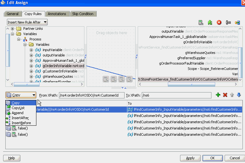
Description of "Figure A-4 Copy Rule Converted to bpelx Extension in BPEL 1.1"
Figure A-5 shows how you select an extension type in BPEL 2.0. You right-click a copy rule, select Change rule type, and then select the appropriate extension.
Figure A-5 Copy Rule Converted to bpelx Extension in BPEL 2.0
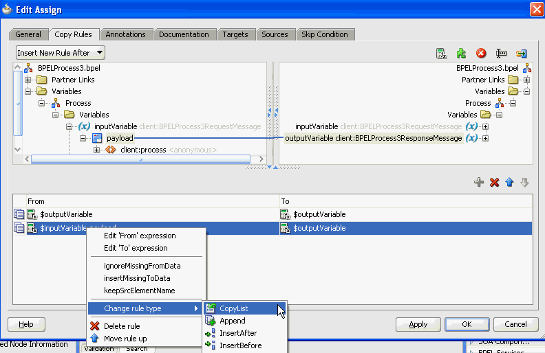
Description of "Figure A-5 Copy Rule Converted to bpelx Extension in BPEL 2.0"
For more information about manipulating XML data with bpelx extensions, see Section 6.15, "Manipulating XML Data with bpelx Extensions."
In the From and To XPath fields, you can also place your cursor over the icon to the left of the source type to display the operation being performed (for example, copy, append, and so on). Each operation type is represented by a different icon. You can also right-click a copy rule to display a list of actions to perform:
-
Edit 'From' expression or Edit 'To' expression: Select this option to edit XPath expression values when the created copy rule contains a query for the source or target node. This selection invokes the Expression Builder dialog. The menu option that displays is based on the current content of your copy rule selection.
-
ignoreMissingFromData: Select this option to toggle the
ignoreMissingFromDataattribute on the copy rule on and off. When toggled on, this suppresses anybpel:selectionFailurestandard faults. -
insertMissingToData: Select this option to toggle the
insertMissingToDataattribute on the copy rule on and off. -
keepSrcElementName (in BPEL 2.0 projects only): Select this option to toggle the
keepSrcElementNameattribute on the copy rule on and off. This option enables you to replace the element name of the destination (as selected by theto-spec) with the element name of the source. -
Change Rule Type (in BPEL 2.0 projects only): Select this option to change the type of the selected rule to one of the BPEL extension rules:
bpelx:copyList,bpelx:insertAfter,bpelx:insertBefore, orbpelx:append. -
Delete rule: Select this option to delete the selected rule.
For more information about the ignoreMissingFromData, insertMissingToData, and keepSrcElementName attributes, see Section 6.15.7, "How to Use Assign Extension Attributes."
The icons above the To section enable you to add, delete, move up, and move down a selected copy rule.
For more information about the assign activity, see the online Help for the Copy Rules dialog and Chapter 6, "Manipulating XML Data in a BPEL Process."
A.2.4 Assert Activity
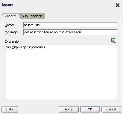
This activity enables you to perform an assertion on a specified expression.
This is a standalone activity in which to specify assertions. This activity can be placed anywhere in the BPEL process flow. You can also specify assertions in message exchange activities from the Assertions tab in invoke activities, reply activities, receive activities, and the onMessage branch of pick and scope activities.
Figure A-6 shows the Assert dialog.
For more information about the standalone assert activity, see Section 12.14.1.7, "Assertion Conditions in a Standalone Assert Activity" and Section 12.14.4, "What Happens When You Create Assertion Conditions."
A.2.5 Bind Entity Activity
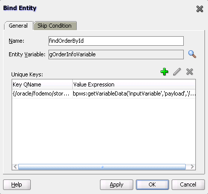
This activity enables you to select the entity variable to act as the data handle to access and plug in different data provider service technologies.
The entity variable can be used with an Oracle Application Development Framework (ADF) Business Component data provider service using service data object (SDO)-based data. The entity variable enables you to specify BPEL data operations to be performed by an underlying data provider service. The data provider service performs the data operations in a data store behind the scenes and without use of other data store-related features provided by Oracle BPEL Process Manager (for example, the database adapter). This action enhances Oracle BPEL Process Manager runtime performance and incorporates native features of the underlying data provider service during compilation and runtime.
Note:
This activity is only supported in BPEL 1.1 projects.Figure A-7 shows the Bind Entity dialog.
A.2.6 Compensate Activity
This activity invokes compensation on an inner scope activity that has successfully completed. This activity can be invoked only from within a fault handler or another compensation handler. Compensation occurs when a process cannot complete several operations after completing others. The process must return and undo the previously completed operations. For example, assume a process is designed to book a rental car, a hotel, and a flight. The process books the car and the hotel, but cannot book a flight for the correct day. In this case, the process performs compensation by unbooking the car and the hotel.The compensation handler is invoked with the compensate activity, which names the scope on which the compensation handler is to be invoked.
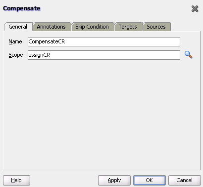
Figure A-8 shows the Compensate dialog in BPEL 1.1. You can perform the following tasks:
-
Click the General tab to provide the activity with a meaningful name.
-
Select the scope activity on which to invoke the compensation handler.
In BPEL 2.0, the Compensate dialog includes a Documentation tab.
For more information about the compensate activity, see Section 12.12, "Using Compensation After Undoing a Series of Operations."
A.2.7 CompensateScope Activity
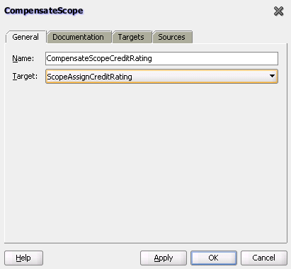
This activity enables you to start compensation on a specified inner scope that has already completed successfully. Only use this activity from within a fault handler, another compensation handler, or a termination handler.
Note:
This activity is only supported in BPEL 2.0 projects.Figure A-9 shows the CompensateScope dialog.
For more information about the compensateScope activity, see Section 12.12, "Using Compensation After Undoing a Series of Operations."
A.2.8 Create Entity Activity
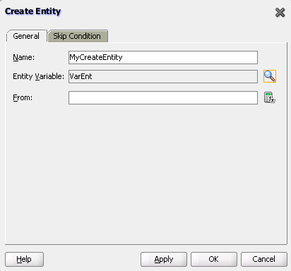
This activity enables you to create an entity variable. The entity variable can be used with an Oracle ADF Business Component data provider service using SDO-based data.
Note:
This activity is only supported in BPEL 1.1 projects.Figure A-10 shows the Create Entity dialog.
For more information, see Section 6.2, "Delegating XML Data Operations to Data Provider Services."
A.2.9 Dehydrate Activity
By default, dehydration points are set on activities such as a wait and a receive. The dehydrate activity enables you to explicitly specify a dehydration point. This activity acts as a dehydration point to automatically maintain long-running asynchronous processes and their current state information in a database while they wait for asynchronous callbacks. Storing the process in a database preserves the process and prevents any loss of state or reliability if a system shuts down or a network problem occurs. This feature increases both BPEL process reliability and scalability.
The bpelx:dehydrate extension implements dehydration. For BPEL projects that support BPEL version 1.1, the syntax is as follows:
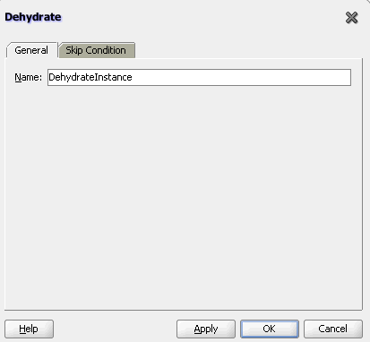
<bpelx:dehydrate name="DehydrateInstance"/>
For BPEL projects that support BPEL version 2.0, the syntax is as shown in Example A-2.
Example A-2 bpelx:dehydrate Extension in BPEL 2.0
<extensionActivity>
      <bpelx:dehydrate name="DehydrateInstance"/>
 </extensionActivity>
Figure A-11 shows the Dehydrate dialog in BPEL 2.0.
A.2.10 Email Activity
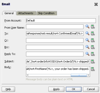
This activity enables you to send an email notification about an event.
For example, an online shopping business process of an online bookstore sends a courtesy email message to you after the items are shipped. The business process calls the notification service with your user ID and notification message. The notification service gets the email address from Oracle Internet Directory.
Figure A-12 shows the Email dialog in BPEL 1.1.
For more information about the email activity, see Section 17.3.1, "How To Configure the Email Notification Channel."
A.2.11 Empty Activity
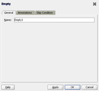
This activity enables you to insert a no-operation instruction into a process. This activity is useful when you must use an activity that does nothing (for example, when a fault must be caught and suppressed).
Figure A-13 shows the Empty dialog in BPEL 1.1.
In BPEL 2.0, the Empty dialog includes a Documentation tab.
For more information about the empty activity, see Section 12.10.9, "How to Create an Empty Activity to Insert No-Op Instructions into a Business Process."
A.2.12 Exit Activity
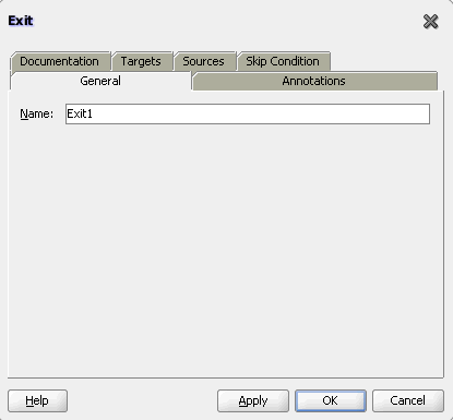
This activity enables you to immediately end all currently running activities on all parallel branches without involving any termination handling, fault handling, or compensation handling mechanisms.
Note:
This activity replaces the terminate activity in BPEL 2.0 projects.Figure A-14 shows the Exit dialog.
For more information about the exit activity, see Section 12.13.2, "Immediately Ending a Business Process Instance with the Exit Activity in BPEL 2.0."
A.2.13 Flow Activity
This activity enables you to specify one or more activities to be performed concurrently. A flow activity completes when all activities in the flow have finished processing. Completion of a flow activity includes the possibility that it can be skipped if its enabling condition is false.
For example, assume you use a flow activity to enable two loan offer providers (United Loan service and Star Loan service) to start in parallel. In this case, the flow activity contains two parallel activities – the sequence to invoke the United Loan service and the sequence to invoke the Star Loan service. Each service can take an arbitrary amount of time to complete their loan processes.
Figure A-15 shows an initial flow activity with its two panels for parallel processing. You drag activities into both panels to create parallel processing. When complete, a flow activity looks as shown in Figure A-16.
Figure A-15 Flow Dialog (At Time of Creation)
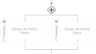
Description of "Figure A-15 Flow Dialog (At Time of Creation)"
Figure A-16 Flow Dialog (After Design Completion)
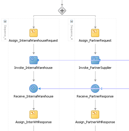
Description of "Figure A-16 Flow Dialog (After Design Completion)"
You can also synchronize the execution of activities within a flow activity. This ensures that certain actives only execute after other activities have completed.
Note:
Oracle's BPEL implementation executes flows in the same, single execution thread of the BPEL process, and not in separate threads.For more information about the flow activity, see Section 10.2, "Creating a Parallel Flow."
A.2.14 FlowN Activity
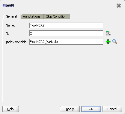
This activity enables you to create multiple flows equal to the value of N, which is defined at runtime based on the data available and logic within the process. An index variable increments each time a new branch is created, until the index variable reaches the value of N.
Note:
This activity is replaced by the forEach activity in BPEL 2.0 projects.Figure A-17 shows the FlowN dialog.
For more information about the flowN activity, see Section 10.3.1, "Customizing the Number of Flow Activities with the flowN Activity in BPEL 1.1."
A.2.15 forEach Activity
This activity enables you to process multiple sets of activities sequentially or in parallel. The forEach activity executes its contained (child) scope activity exactly N+1 times, where N equals the final counter value minus the starting counter value that you specify in the Counter Values tab of the For Each dialog. While other structured activities such as a flow activity can have any type of activity as its contained activity, the forEach activity can only use a scope activity.
Note:
This activity replaces the flowN activity in BPEL 2.0 projects.Figure A-18 shows a forEach activity with its contained scope.
For more information about the forEach activity, see Section 10.3.2, "Processing Multiple Sets of Activities with the forEach Activity in BPEL 2.0."
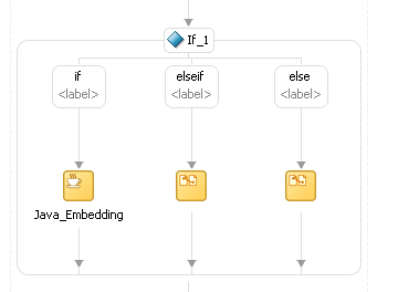
A.2.16 If Activity
This activity enables you to define conditional behavior for specific activities to decide between two or more branches. Only one activity is selected for execution from a set of branches.
Note:
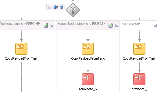
This activity replaces the switch activity in BPEL 2.0 projects.Figure A-19 shows an if activity with the following defined if, elseif, and else branches.
For more information about the if activity, see Section 11.2.2, "Defining Conditional Branching with the If Activity in BPEL 2.0."
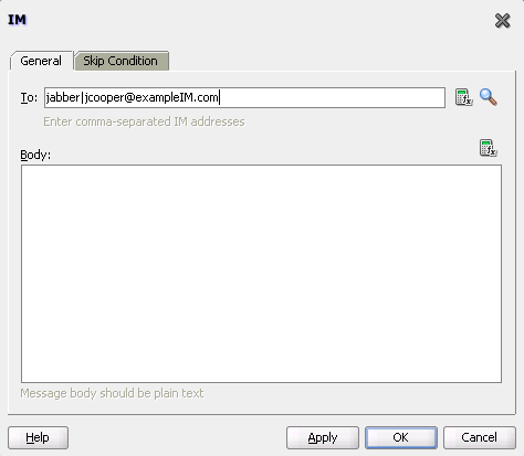
A.2.17 IM Activity
This activity enables you to send an automatic, asynchronous instant message (IM) notification to a user, group, or destination address. Figure A-20 shows the IM dialog.
For more information, see Section 17.3.2, "How to Configure the IM Notification Channel."
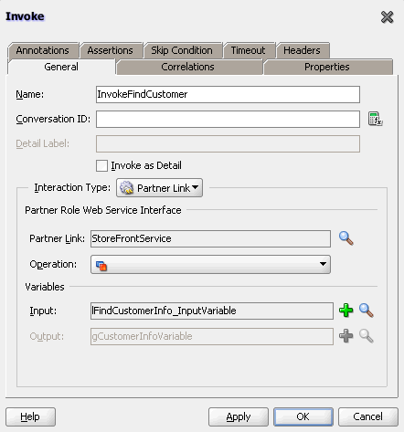
A.2.18 Invoke Activity
This activity enables you to specify an operation you want to invoke for the service (identified by its partner link). The operation can be one-way or request-response on a port provided by the service. You can also automatically create variables in an invoke activity. An invoke activity invokes a synchronous web service or initiates an asynchronous web service.
The invoke activity opens a port in the process to send and receive data. It uses this port to submit required data and receive a response. For synchronous callbacks, only one port is needed for both the send and receive functions.
The invoke activity supports the bpelx:inputProperty and bpelx:outputProperty extensions to pass properties through the SOAP header and obtain SOA runtime system properties for useful information such as the tracking.compositeInstanceId and tracking.conversationId.
Figure A-21 shows the Invoke dialog in BPEL 1.1. You can perform the following tasks:
-
Provide the activity with a meaningful name.
-
Select the partner link for which to specify an operation.
-
Select the operation to perform.
-
Automatically create a variable or select an existing variable in which to transport the data (payload).
In BPEL 2.0, the Invoke dialog includes the Documentation, Targets, and Sources tabs. For more information about the invoke activity, see the following:
A.2.19 Java Embedding Activity
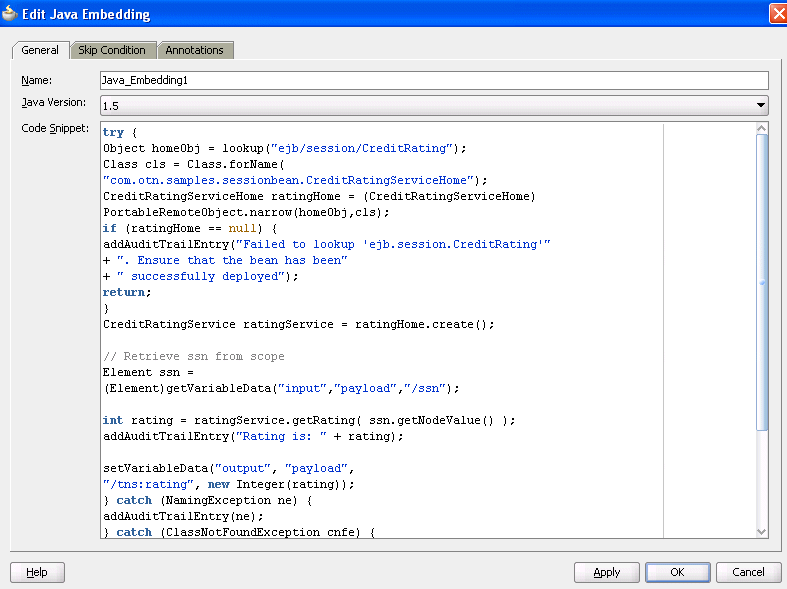
This activity enables you to add custom Java code to a BPEL process using the Java BPEL extension bpelx:exec. This is useful when you have Java code that can perform a function, and want to use this existing code instead of starting over. In BPEL 2.0 projects, the bpelx:exec extension and Java code are wrapped in an <extensionActivity> element.
Figure A-22 shows the Edit Java Embedding dialog in BPEL 1.1.
For more information about the Java embedding activity, see Chapter 14, "Incorporating Java and Java EE Code in a BPEL Process."
A.2.20 Partner Link Activity
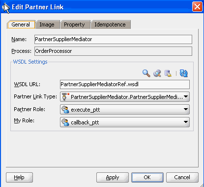
This activity enables you to define the external services with which your process interacts. A partner link type characterizes the conversational relationship between two services by defining the roles played by each service in the conversation and specifying the port type provided by each service to receive messages within the conversation. For example, if you create a process to interact with a Credit Rating Service and two loan provider services (United Loan and Star Loan), you create partner links for all three services.
Figure A-23 shows the Partner Link dialog in BPEL 1.1. You provide the following details:
-
A meaningful name for the service.
-
The web services description language (WSDL) file of the external service.
-
The actual service type (defined as Partner Link Type).
-
The role of the service (defined as Partner Role).
-
The role of the process requesting the service (defined as My Role).
In BPEL 2.0, the Partner Link dialog also includes the Documentation tab.
For more information about partner links, see Chapter 8, "Invoking an Asynchronous Web Service from a BPEL Process."
A.2.21 Phase Activity
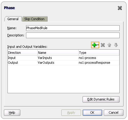
This activity creates Oracle Mediator and business rules service components for integration with a BPEL process. You create message request input and message response output variables and design business rules for evaluating variable content for the BPEL process.
When you complete these tasks, the following activities and service components are created:
-
An assign activity that includes the message request input and message response output variables.
-
An invoke activity that is automatically designed to invoke an Oracle Mediator partner link in the BPEL process.
-
An Oracle Mediator partner link that is automatically designed to route the message request input variable to the business rules service component in the SOA composite application of which this BPEL process is a part. The business rules service component displays in the SOA Composite Editor. Oracle Mediator also displays as a service component in the SOA Composite Editor.
-
A business rules service component that evaluates the content of the message request input variable and returns the results in the message response output variable to Oracle Mediator. Oracle Mediator then makes a routing decision and routes the message to the correct target destinations.
Figure A-24 shows the Phase dialog in BPEL 1.1.
In BPEL 2.0, the Phase dialog includes the Documentation tab.
For more information, see Chapter 51, "Using Two-Layer Business Process Management (BPM)."
A.2.22 Pick Activity
This activity waits for the occurrence of one event in a set of events and performs the activity associated with that event. The occurrence of events is often mutually exclusive (the process either receives an acceptance or rejection message, but not both). If multiple events occur, the selection of the activity to perform depends on which event occurred first. If the events occur nearly simultaneously, there is a race and the choice of activity to be performed is dependent on both timing and implementation.
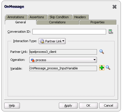
The pick activity provides an OnMessage branch. When you double-click the OnMessage icon in BPEL 1.1, the dialog shown in Figure A-25 appears.
In BPEL 2.0, the OnMessage dialog includes a Documentation tab.
The two branches of the pick activity are as follows:
-
OnMessage (Automatically displays below the Pick activity icon.)
Contains the code for receiving a reply, for example, from a loan service.
-
OnAlarm (Does not automatically display; you must manually add this branch by selecting the Pick activity icon and clicking the Add OnAlarm icon.)
Contains the code for a timeout, for example, after one minute.
Whichever branch completes first is executed; the other branch is not executed. The branch that has its condition satisfied first is executed.
Figure A-26 shows the OnAlarm dialog of the pick activity in BPEL 1.1.
Figure A-26 OnAlarm Branch Dialog of a Pick Activity
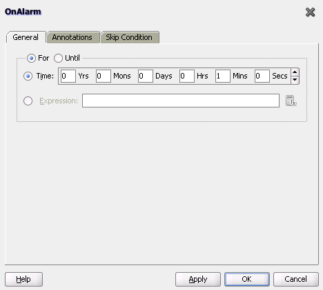
Description of "Figure A-26 OnAlarm Branch Dialog of a Pick Activity"
In BPEL 2.0, the OnAlarm dialog includes a Documentation tab.
Note:
You can also create OnMessage branches in BPEL 1.1 scope activities and OnAlarm branches in BPEL 1.1 and 2.0 scope activities. Expand the Scope activity in Oracle JDeveloper, and browse the icons on the left side to find the branch you want to add.If you add correlations to an OnMessage branch, the correlations syntax is placed after the assign activity syntax. The correlation syntax must go before the assign activity.
To put the correlation syntax before the assign activity:
-
Create a correlation set in Oracle JDeveloper.
-
Assign this to the OnMessage branch.
-
Complete the remaining design tasks.
-
Before making or deploying the BPEL process, move the correlation syntax before the assign activity in the BPEL source code.
For more information about the pick activity, see the following:
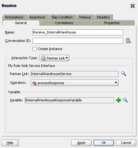
A.2.23 Receive Activity
This activity specifies the partner link from which to receive information and the port type and operation for the partner link to invoke. This activity waits for an asynchronous callback response message from a service, such as a loan application approver service. While the BPEL process is waiting, it is dehydrated (compressed and stored) until the callback message arrives. The contents of this response are stored in a response variable in the process.
The receive activity supports the bpelx:property extensions that facilitate the passing of properties through the SOAP header, and the obtaining of SOA runtime system properties for useful information such as tracking.compositeInstanceId and tracking.conversationId.
Figure A-27 shows the Receive dialog in BPEL 1.1. You can perform the following tasks:
-
Provide a meaningful name.
-
Select the partner link service for which to specify an operation.
-
Select the operation to be performed.
-
Automatically create a variable or select an existing variable in which to transport the callback response.
In BPEL 2.0, the Receive dialog includes the Documentation, Targets, and Sources tabs.
For more information about the receive activity, see the following:
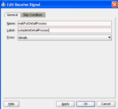
A.2.24 Receive Signal Activity
Use this activity in detail processes to wait for the notification signal from the master process to begin processing and in a master process to wait for the notification signal from all detail processes indicating that processing has completed.
Figure A-28 shows the Edit Receive Signal dialog.
For more information, see Chapter 16, "Coordinating Master and Detail Processes."
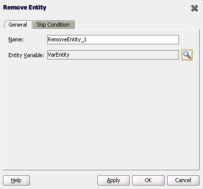
A.2.25 Remove Entity Activity
This activity enables you to remove an entity variable. This action removes the row.
Note:
This activity is only supported in BPEL 1.1 projects.Figure A-29 shows the Remove Entity dialog.
A.2.26 RepeatUntil Activity
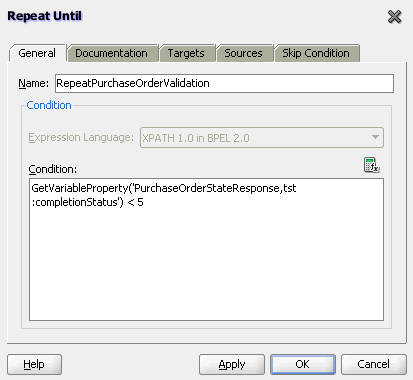
Use this activity if the body of an activity must be performed at least once. The XPath expression condition in the repeatUntil activity is evaluated after the body of the activity completes. The condition is evaluated repeatedly (and the body of the activity processed) until the provided boolean condition is true. Figure A-30 shows the Repeat Until dialog.
Note:
This activity is only supported in BPEL 2.0 projects.For more information about the repeatUntil activity, see, Section 11.4, "Defining Conditional Branching with the repeatUntil Activity."
A.2.27 Replay Activity
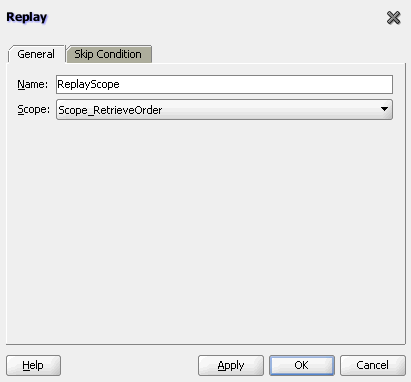
This activity enables you to re-execute the activities inside a selected scope.
Figure A-31 shows the Replay dialog in BPEL 1.1.
In BPEL 1.1, the Replay dialog does not include a Documentation tab, Targets tab, or Sources tab. For more information about the replay activity, see Section 12.11, "Re-executing Activities in a Scope Activity with the Replay Activity."
A.2.28 Reply Activity
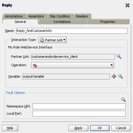
This activity allows the process to send a message in reply to a message that was received through a receive activity. The combination of a receive activity and a reply activity forms a request-response operation on the WSDL port type for the process.
Figure A-32 shows the Reply dialog in BPEL 1.1.
In BPEL 2.0, the Reply dialog includes the Documentation, Targets, and Sources tabs.
For more information about the reply activity, see the following:
A.2.29 Rethrow Activity
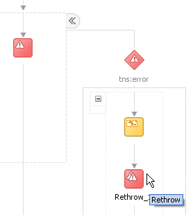
This activity enables you to rethrow a fault originally captured by the immediately enclosing fault handler.
Note:
This activity is only supported in BPEL 2.0 projects.Figure A-33 shows a rethrow activity within a fault handler (catch activity).
For more information about rethrowing faults, see Section 12.8, "Rethrowing Faults with the Rethrow Activity."
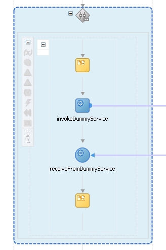
A.2.30 Scope Activity
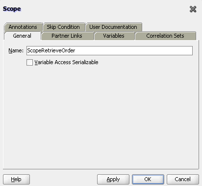
This activity consists of a collection of nested activities that can have their own local variables, fault handlers, compensation handlers, and so on. A scope activity is analogous to a { } block in a programming language.
Each scope has a primary activity that defines its behavior. The primary activity can be a complex structured activity, with many nested activities within it of arbitrary depth. The scope is shared by all the nested activities.
Figure A-34 shows the Scope dialog in BPEL 1.1. Define appropriate activities inside the scope activity.
In BPEL 2.0, the Scope dialog includes the Documentation, Targets, and Sources tabs.
Fault handling is associated with a scope activity. The goal is to undo the incomplete and unsuccessful work of a scope activity in which a fault has occurred. You define catch activities in a scope activity to create a set of custom fault-handling activities. Each catch activity is defined to intercept a specific type of fault.
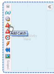
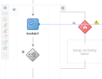
Figure A-35 shows the Add Catch icon inside a scope activity. Figure A-36 shows the catch activity area that appears when you click the Add Catch icon. Within the area defined as Drop Activity Here, you drag additional activities to create fault handling logic to catch and manage exceptions.
For example, a client provides a social security number to a credit rating service when applying for a loan. This number is used to perform a credit check. If a bad credit history is identified or the social security number is identified as invalid, an assign activity inside the catch activity notifies the client of the loan offer rejection. The entire loan application process is terminated with a terminate activity.
For more information about the scope activity and fault handling, see the following:
A.2.31 Sequence Activity
This activity enables you to define a collection of activities to perform in sequential order. For example, you may want the following activities performed in a specific order:
-
A customer request is received in a receive activity.
-
The request is processed inside a flow activity that enables concurrent behavior.
-
A reply message with the final approval status of the request is sent back to the customer in a reply activity.
A sequence activity makes the assumption that the request can be processed in a reasonable amount of time, justifying the requirement that the invoker wait for a synchronous response (because this service is offered as a request-response operation).
When this assumption cannot be made, it is better to define the customer interaction as a pair of asynchronous message exchanges.
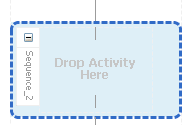
When you double-click the Sequence icon, the activity area shown in Figure A-37 appears. Drag and define appropriate activities inside the sequence activity.
For more information about the sequence activity, see the following:
A.2.32 Signal Activity
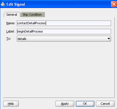
This activity is used in a master process to notify detail processes to perform processing at runtime and used in detail processes to notify a master process that processing has completed. Figure A-38 shows the Edit Signal dialog.
For more information, see Chapter 16, "Coordinating Master and Detail Processes."
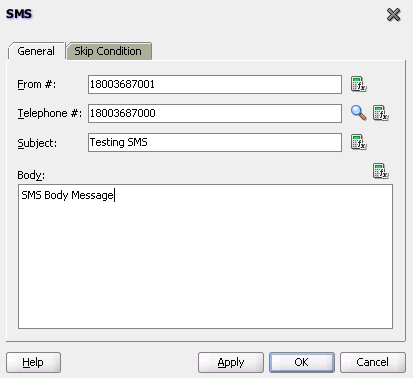
A.2.33 SMS Activity
This activity enables you to send a short message system (SMS) notification about an event.
Figure A-39 shows the SMS dialog in BPEL 1.1 and BPEL 2.0.
For more information about the SMS activity, see Section 17.3.3, "How to Configure the SMS Notification Channel."
Note:
The fax and pager activities are not supported in 11g.A.2.34 Switch Activity
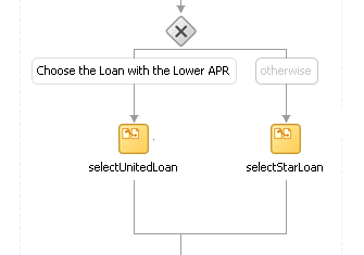
This activity consists of an ordered list of one or more conditional branches defined in a case branch, followed optionally by an otherwise branch. The branches are considered in the order in which they appear. The first branch whose condition is true is taken and provides the activity performed for the switch. If no branch with a condition is taken, then the otherwise branch is taken. If the otherwise branch is not explicitly specified, then an otherwise branch with an empty activity is assumed to be available. The switch activity is complete when the activity of the selected branch completes.
A switch activity differs in functionality from a flow activity. For example, a flow activity enables a process to gather two loan offers at the same time, but does not compare their values. To compare and make decisions on the values of the two offers, a switch activity is used. The first branch is executed if a defined condition (inside the case branch) is met. If it is not met, the otherwise branch is executed.
Note:
This activity is replaced by the if activity in BPEL 2.0 projects.Figure A-40 shows a switch activity with the following defined branches.
For more information about the switch activity, see the following:
A.2.35 Terminate Activity
This activity enables you to end the tasks of an activity (for example, the fault handling tasks in a catch branch). For example, if a client's bad credit history is identified or a social security number is identified as invalid, a loan application process is terminated, and the client's loan application document is never submitted to the service loan providers.
Note:
This activity is replaced by the exit activity in BPEL 2.0 projects.Figure A-41 shows several terminate activities in the otherwise branch of a switch activity.
For more information about the terminate activity, see Section 12.13.1, "Stopping a Business Process Instance with the Terminate Activity in BPEL 1.1."
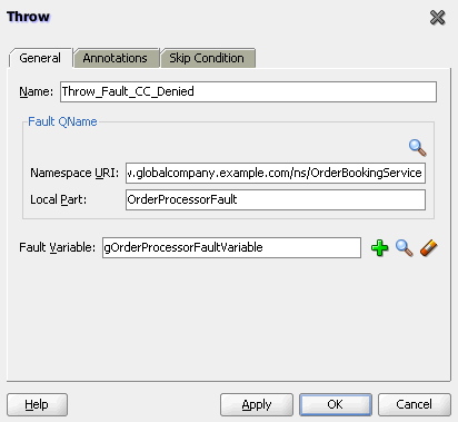
A.2.36 Throw Activity
This activity generates a fault from inside the business process.
Figure A-42 shows the Throw dialog in BPEL 1.1.
In BPEL 2.0, the Throw dialog includes the Documentation, Targets, and Sources tabs.
For more information about the throw activity, see Section 12.7, "Throwing Internal Faults with the Throw Activity."
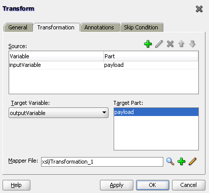
A.2.37 Transform Activity
This activity enables you to create a transformation that maps source elements to target elements (for example, incoming purchase order data into outgoing purchase order acknowledgment data).
Figure A-43 shows the Transform dialog in BPEL 1.1. This dialog enables you to perform the following tasks:
-
Define the source and target variables and parts to map.
-
Specify the transformation mapper file.
-
Click the second icon (the Add icon) to the right of the Mapper File field to access the XSLT Mapper for creating a new XSL file for graphically mapping source and target elements. Click the Edit icon (third icon) to edit an existing XSL file.
In BPEL 2.0, the Transform dialog includes the Documentation, Targets, and Sources tabs.
For more information about the transform activity, see Chapter 40, "Creating Transformations with the XSLT Mapper."
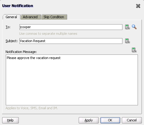
A.2.38 User Notification Activity
This activity enables you to design a BPEL process in which you do not explicitly select a notification channel during design time, but simply indicate that a notification must be sent. The channel to use for sending notifications is resolved at runtime based on preferences defined by the end user in the User Messaging Preferences user interface of the Oracle User Messaging Service. This moves the responsibility of notification channel selection from Oracle BPEL Designer to the end user. If the end user does not select a preferred channel or rule, email is used by default for sending notifications to that user. Figure A-44 provides details.
For more information, see Section 17.4, "Allowing the End User to Select Notification Channels."
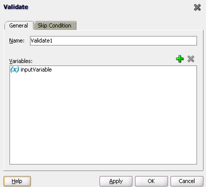
A.2.39 Validate Activity
This activity enables you to validate variables in the list. The variables are validated against their XML schema.
Figure A-45 shows the Validate dialog in BPEL 1.1.
In BPEL 2.0, the Validate dialog includes the Documentation, Targets, and Sources tabs
For more information about the validate activity, see Section 6.16, "Validating XML Data."
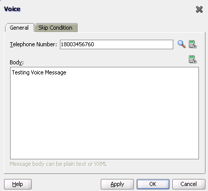
A.2.40 Voice Activity
This activity enables you to send a telephone voice notification about an event.
Figure A-46 shows the Voice dialog.
For more information about the voice activity, see Section 17.3.4, "How to Configure the Voice Notification Channel."
A.2.41 Wait Activity
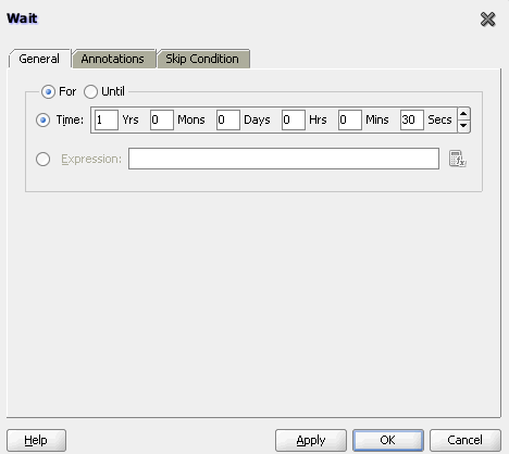
This activity allows a process to specify a delay for a certain period or until a certain deadline is reached. A typical use of this activity is to invoke an operation at a certain time. This activity enables you to wait for a given time period or until a certain time has passed. Exactly one of the expiration criteria must be specified.
Figure A-47 shows the Wait dialog in BPEL 1.1.
In BPEL 2.0, the Wait dialog includes the Documentation, Targets, and Sources tabs.
For more information about the wait activity, see Section 15.4, "Creating a Wait Activity to Set an Expiration Time."
A.2.42 While Activity
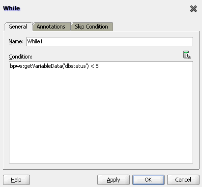
This activity supports repeated performance of a specified iterative activity. The iterative activity is repeated until the given while condition is no longer true.
Figure A-48 shows the While dialog in BPEL 1.1. You can enter expressions in this dialog.
In BPEL 2.0, the While dialog includes the Documentation, Targets, and Sources tabs.
For more information about the while activity, see Section 11.3, "Defining Conditional Branching with the While Activity."
A.3 Introduction to BPEL Services
BPEL processes can communicate with web-based applications and clients through web services, Oracle ADF Business Component (BC) services, JCA adapters, Oracle B2B services, Oracle Healthcare services, Oracle Business Activity Monitoring, HTTP binding, direct binding, EJB services, Oracle E-Business Suite, and partner links.
-
In the Component Palette of Oracle BPEL Designer, expand BPEL Services to display the services.
-
Drag and drop the service to the appropriate swimlane. Table A-2 lists the available services and provides references to documentation that describes these services.
BPEL Service For More Information, See... Oracle User Messaging Service
Healthcare adapter
A.4 Publishing and Browsing the Oracle Service Registry
The Oracle Service Registry (OSR) provides a common standard for publishing and discovering information about web services. This section describes how to configure OSR against a separately installed Oracle SOA Suite environment.
You can use Oracle SOA Suite with the following versions of OSR:
-
OSR 11g
-
OSR 10.3 (with Oracle WebLogic Server 10.3)
-
OSR 10.1.3
For more information about OSR, visit the following URL:
http://www.oracle.com/technetwork/middleware/registry/overview/index.html
Notes:
-
This section does not describe how to configure OSR against the embedded Oracle WebLogic Server in Oracle JDeveloper.
-
OSR 10.3 deploys to the 10.3.0.0 version of Oracle WebLogic Server.
-
OSR 10.3 does not support the 10.3.1.0 version of Oracle WebLogic Server.
A.4.1 How to Publish a Business Service
This section provides an overview of how to publish a business service. For specific instructions, see the documentation at the following URL:
http://www.oracle.com/technetwork/middleware/registry/overview/index.html
You can also access the documentation by clicking the Registry Documentation link.
To publish a business service:
-
Go to the Registry Control:
http://hostname:port/registry/uddi/web
-
Click Publish > WSDL.
-
Log in when prompted.
-
Complete the fields on this page to specify the access point URL and publish the WSDL for the business service.
Note:
If you later change your endpoint location, you must also update the WSDL location in the Registry Control. Otherwise, UDDI invocation fails during runtime. See section Section A.4.4.1, "Changing Endpoint Locations in the Registry Control."
A.4.2 How to Create a Connection to the Registry
To create a connection to the registry:
-
Go to Oracle JDeveloper.
-
Select File > New > Connections > UDDI Registry Connection to create a UDDI connection.
-
Enter a connection name.
-
Enter an inquiry endpoint URL. For example:
http://myhost.us.example.com:7001/registry/uddi/inquiry
-
Ensure that the Business View option is selected.
-
Click Next.
-
Click Test Connection.
-
If successful, click Finish. Otherwise, click the Back button and correct your errors.
A.4.3 How to Configure a SOA Project to Invoke a Service from the Registry
To configure a SOA project to invoke a service from the registry:
-
Open the SOA project in which to create a reference to the business service.
-
Drag a Web Service icon into the External References swimlane.
The Create Web Service dialog appears.
-
To the right of the WSDL URL field, click the icon to select a WSDL.
-
From the list at the top, select Resource Palette.
-
Expand the navigational tree.
-
Expand UDDI Registry > Business Services.
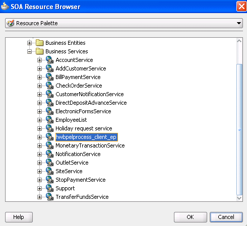
-
Select the published business service, and click OK. Figure A-49 provides details.
The UDDI Deployment Options dialog appears.
-
Select one of the following deployment options:
-
Dynamically resolve the SOAP endpoint location at runtime
-
Dynamically resolve the concrete WSDL location at runtime
Figure A-50 provides details.
Figure A-50 UDDI Deployment Options Dialog
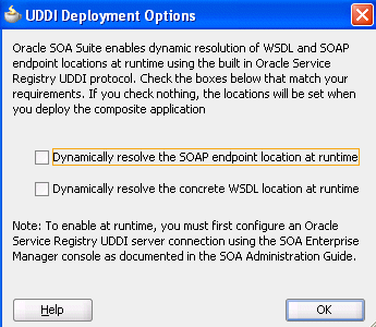
Description of "Figure A-50 UDDI Deployment Options Dialog"
-
-
Click OK.
You are returned to the Create Web Service dialog.
-
See the following section based on your selection in the UDDI Deployment Options dialog.
A.4.3.1 Dynamically Resolving the SOAP Endpoint Location
To dynamically resolve the SOAP endpoint location:
-
Complete the remaining fields in the Create Web Service dialog, and click OK.
The Create Web Service dialog looks as shown in Figure A-51.
Figure A-51 Create Web Service Dialog - SOAP Endpoint Location
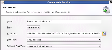
Description of "Figure A-51 Create Web Service Dialog - SOAP Endpoint Location"
-
Wire the reference with the appropriate service component.
-
In the SOA Composite Editor, click Source.
The
composite.xmlfile shows theserviceKey. The property dynamically resolves the endpoint binding location at runtime.<property name="oracle.soa.uddi.servicekey" type="xs:string" many="false">uddi: d3611b59-1c79-478e-9ae5-874007eb20c4">
-
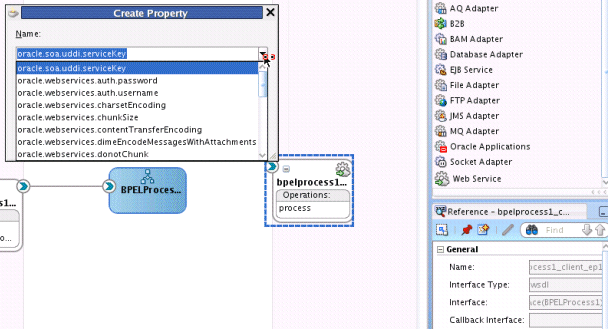
If you want, you can also resolve the SOAP endpoint location by explicitly adding the
oracle.soa.uddi.servicekeyproperty in the Property Inspector. This action dynamically resolves the SOAP endpoint location at runtime for any external reference to a web service. Figure A-52 provides details.-
Highlight the reference binding component in the External References swimlane.
-
In the Property Inspector, expand the Properties section.
-
Click the Add icon.
-
In the Name list, select oracle.soa.uddi.servicekey.
-
In the Value field, specify the value for oracle.soa.uddi.servicekey from the
composite.xmlfile.
-
A.4.3.2 Dynamically Resolving the WSDL Endpoint Location
To dynamically resolve the WSDL endpoint location:
-
Complete the remaining fields in the Create Web Service dialog, and click OK.
The Create Web Service dialog looks as shown in Figure A-53.
Figure A-53 Create Web Service Dialog - WSDL Endpoint Location
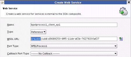
Description of "Figure A-53 Create Web Service Dialog - WSDL Endpoint Location"
-
Wire the reference with the appropriate service component.
-
In the SOA Composite Editor, click Source.
The
composite.xmlfile shows that the WSDL location is an abstract URL oforauddi:/uddi_service_keyinstead of a concrete URL (such as a HTTP URL). Theorauddiprotocol dynamically resolves the WSDL location at runtime.<location="orauddi:/uddi:d3689250-6ff5-11de-af2b-76279200af27">
A.4.3.3 Resolving Endpoints
Oracle SOA Suite invokes a service for resolving an endpoint. Examples and descriptions are shown in Table A-3.
| Endpoint Resolutions | Description | Example |
|---|---|---|
|
Normalized message UDDI |
The OSR UDDI |
For example, with Oracle Mediator: <copy target="$out.property.oracle.soa.uddi.serviceKey" value="uddi:10a55fa0-99e8-11df-9edf-7d5e3ef09eda"/> |
|
Normalized message |
The normalized message |
For example, with Oracle Mediator:
<copy target="$out.property.endpointURI"
value="http://hostname:8001/soa-infra/services
/partition/Project/endpoint_ep"/>
|
|
|
The OSR UDDI Note: This can be overwritten in Oracle Enterprise Manager Fusion Middleware Control. |
<binding.ws port="http://xmlns.oracle.com/UDDIPublishApplication /Proj/BPELProcess1#wsdl.endpoint(bpelprocess1_client _ep/BPELProcess1_pt)" . . .> <property name="oracle.soa.uddi.serviceKey" type="xs:string" many="false">uddi:31040650-9ce7-11df-9ee1-7d5e3e f09eda</property> </binding.ws> |
|
|
The Note: This can be overwritten in Oracle Enterprise Manager Fusion Middleware Control. |
<binding.ws
 port="http://xmlns.oracle.com/UDDIPublishApplica
 tion/Project/BPELProcess1#wsdl.endpoint(bpelproc
 ess1_client_ep/BPELProcess1_pt)"
 . . . >
 <property name="oracle.soa.uddi.endpointURI"
 value="http://hostname:8001/soa-infra/services/
 Partition/Project/bpelprocess1_client_ep"</property>
</binding.ws>
|
|
|
The endpoint location is specified in the concrete WSDL in the binding component section of |
<binding.ws
 port="http://xmlns.oracle.com/UDDIPublishApplication
 /Project/BPELProcess1#wsdl.endpoint(bpelprocess1_
 client_ep/BPELProcess1_pt)"
 location="http://hostname:8001/soa-infra/services
 /Partition/Project/bpelprocess1_client_ep?wsdl"
 soapVersion="1.1">
|
The failover scenario for resolving endpoints is as follows.
-
Normalized message UDDI
serviceKey-
Any error on the endpoint access
-
Log a severe error
-
Return an error to the user
-
-
-
Normalized message
endpointURI-
Any error on the endpoint access
-
Log a severe error
-
Return an error to the user
-
-
-
composite.xmlUDDIserviceKey-
Error on an OSR connection
-
Log a severe error
-
Use the
composite.xmlendpointURIif it is coded -
Else, return an error to the user
-
-
Error for an invalid
serviceKeyin the connection-
Log a severe error
-
Use the
composite.xmlendpointURIif it is coded -
Else, return an error to the user
-
-
Error on the endpoint access
-
Log a warning error
-
Use a second (or third) binding template if it exists.
-
Else, fail over to the
composite.xmlendpointURI
-
-
-
composite.xmlendpointURI-
Error on the endpoint access
-
Log a warning error
-
Fail over to the
composite.xmlconcrete WSDL endpoint location
-
-
-
composite.xmlconcrete WSDL endpoint location-
Error on the endpoint access
-
Log a severe error
-
Return an error to the user
-
-
A.4.4 How To Configure the Inquiry URL, UDDI Service Key, and Endpoint Address for Runtime
You can set the inquiry URL, UDDI service key, and endpoint address during runtime in Oracle Enterprise Manager Fusion Middleware Control.
To configure the inquiry URL, UDDI service key, and endpoint reference for runtime:
-
Log in to Oracle Enterprise Manager Fusion Middleware Control.
-
Specify values for the following properties:
-
In the SOA Infrastructure Common Properties page, specify the same UDDI inquiry URL that you specified in the Create UDDI Registry Connection wizard. For information, see section "Configuring SOA Infrastructure Properties" of Oracle Fusion Middleware Administrator's Guide for Oracle SOA Suite and Oracle Business Process Management Suite.
-
In the Properties page of the reference binding component, you can change the endpoint reference and service key values created during design time. For information, see section "Configuring Service and Reference Binding Component Properties" of Oracle Fusion Middleware Administrator's Guide for Oracle SOA Suite and Oracle Business Process Management Suite.
-
-
Restart the SOA Infrastructure.
-
Exit Oracle Enterprise Manager Fusion Middleware Control.
-
To see endpoint statistics, return to the Registry Control.
-
Go to the Manage page and check statistics to see the increase in the number of invocations when not cached (the first time).
Caching of WSDL URLs occurs by default during runtime. If a WSDL URL is resolved using the orauddi protocol, subsequent invocations retrieve the WSDL URLs from cache, and not from OSR. When an endpoint WSDL obtained from cache is no longer reachable, the cache is refreshed and OSR is contacted to retrieve the new endpoint WSDL location. As a best practice, Oracle recommends that you undeploy services that are no longer required in Oracle Enterprise Manager Fusion Middleware Control and used by the SOA Infrastructure. Endpoint services that are shut down or retired (but not undeployed) are still reachable. Therefore, the cache is not refreshed.
If you move the business service WSDL from one host to another, ensure that you change the location in the Registry Control. No change is required in Oracle JDeveloper or Oracle Enterprise Manager Fusion Middleware Control.
You can optionally increase the amount of time that the WSDL URL is available in cache for inquiry by the service key. For more information, see "Configuring Service and Reference Binding Component Properties" of Oracle Fusion Middleware Administrator's Guide for Oracle SOA Suite and Oracle Business Process Management Suite.
Note:
In 11g, caching occurs automatically. If you are using Oracle SOA Suite 10.1.3, caching is supported by setting theCacheRegistryWSDLproperty totrueinbpel.xml. Setting this property tofalsedisables caching.
A.4.4.1 Changing Endpoint Locations in the Registry Control
The Registry Control provides an option for changing the endpoint location. This is a two-step process. The following steps provide an overview. For more specific details, see the Oracle Service Registry documentation:
http://www.oracle.com/technetwork/middleware/registry/overview/index.html
-
Log in to Registry Control.
-
Click Search > Business.
-
Click Add Name.
-
In the Name field, enter a search criteria.
-
Click Find.
-
In the search results, click the business name that is displayed.
-
On the right side, click the Services tab.
-
From the list of services, click the service name.
-
At the bottom, click the Edit button.
-
On the right side, click the Bindings tab.
-
In the list of bindings, select the notepad icon next to the description column.
Oracle Service Registry is now in edit mode for bindings.
-
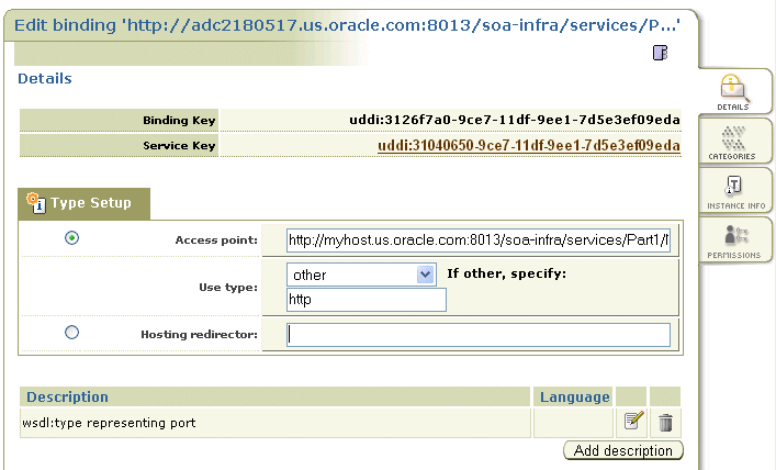
In the Access Point field, change the required URL, and save your changes. Figure A-54 provides details.
To update WSDL binding overview documentation:
-
Within the Registry Control, click Search.
-
In the tModel name field, enter the name and click Find tModel.
-
In the name column, click the name with the description wsdl:type representing portType.
-
Ensure that WSDL details are shown correctly.
-
Click the Edit button.
-
On the right side, click the Overview doc tab.
-
Under the Add description button, click the Edit icon.
-
Enter the new URL.
-
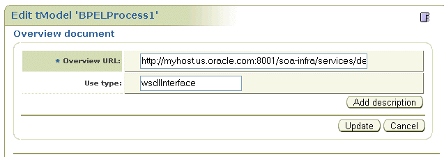
Click Update and save the changes. Figure A-55 provides details.
-
To verify, navigate to the service and ensure that the WSDL URL is pointing to a new location.
A.4.4.2 Publishing WSDLs from Multiple SOA Partitions
Follow these steps to publish WSDLs from multiple SOA partitions using the Registry Control, and access them using a separate serviceKey and bindings.
To publish WSDLs from multiple SOA partitions:
-
Log in to Registry Control.
http://host:port/registry/uddi/web
-
Publish the WSDL from the first partition.
-
Publish the WSDL from the second partition.
-
Click Publish > WSDL.
-
Enter values in the Business key and WSDL location (URI) fields.
-
Select the Advanced Mode checkbox.
-
Click Publish.
-
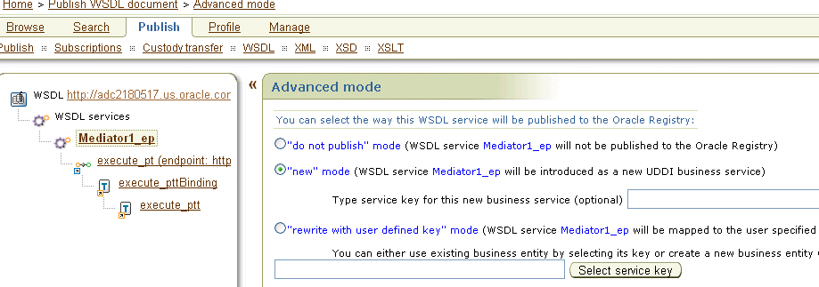
In the navigation tree in the left pane, select the endpoint, bindings, and port type, and ensure that the "new" mode option is selected. Figure A-56 provides details.
-
Click Publish.
-
A.4.5 How to Publish WSDLs to UDDI for Multiple Partitions
The following limitations exist for publishing WSDL services from Oracle Enterprise Manager Fusion Middleware Control.
-
You cannot publish the same service with the same target namespace from different SOA partitions or from different hosts.
-
There is no option for entering your own service key.
Instead, use the Registry Console to publish the same WSDL service deployed to different partitions to OSR.
To publish WSDLs to UDDI for multiple partitions:
-
Log in to the Registry Console.
-
Publish the WSDL of the first partition.
-
Rename the above-mentioned service name to a unique name.
-
Publish the WSDL of the second partition.
This creates two separate services in OSR.
A.5 Providing Design-time Governance with the Oracle Enterprise Repository
The Oracle Enterprise Repository provides design-time governance in support of the service life cycle, delivering capabilities for the storage and management of metadata for composites, services, business processes, and other IT-related assets.
Oracle Enterprise Repository acts as the central source of Oracle SOA Suite information, providing all participants in the service life cycle with a human-centric discovery environment for planned, existing, and retired services.
Oracle Enterprise Repository provides role-based links to the artifact stores of the assets that it describes and links to design documents, justification documents, test plans, support plans, policies, and other forms of documentation.
From an integrated development environment (IDE) such as Oracle JDeveloper, you can perform the following tasks:
-
Harvest Oracle SOA Suite project artifacts, including BPEL, WSDL, XSD, and XSLT files and file directories. After harvesting, the Oracle Enterprise Repository automatically creates assets, populates asset metadata, and generates relationship links based on the information in the artifact files.
-
Browse for assets and artifacts available in the Oracle Enterprise Repository.
-
View asset details such as description, usage history, expected savings, and relationships.
-
Download an asset's artifacts (that is, payload) into your project. Typically, an asset payload is the functionality required for using a service (such as a WSDL file) or incorporating it into your code base (such as a binary or a BPEL file).
-
Consume a WSDL file or a service from the Oracle Enterprise Repository.
For more information about these tasks and how to configure and use Oracle Enterprise Repository with an IDE, see the Oracle Fusion Middleware Integration Guide for Oracle Enterprise Repository.
For more information about harvesting from Oracle JDeveloper, see the Oracle Fusion Middleware Configuration Guide for Oracle Enterprise Repository.
A.6 Validating When Loading a Process Diagram
You may see an icon (a yellow triangle with an exclamation point) indicating invalid settings as you create and open activities such as a scope or an assign for the first time. The settings are invalid because you have not yet entered details. To turn this option off for the current project, perform the following steps.
To disable process diagram validation:
-
Right-click the BPEL diagram and select Display > Diagram Properties.
-
Deselect the Enable Automatic Validation option.
-
Click OK.
-
From the File main menu, select Save All.
