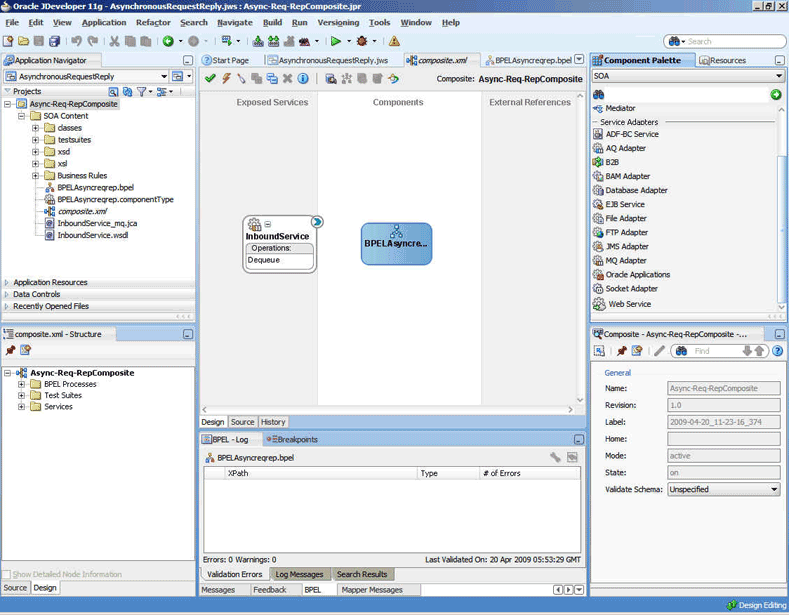
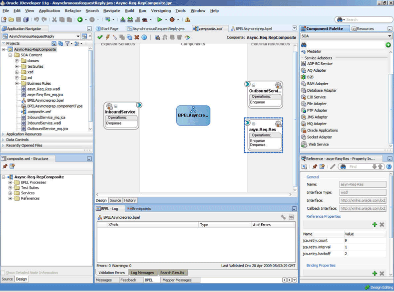
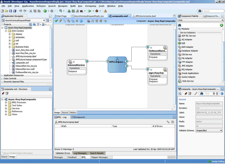
10 Oracle JCA Adapter for MQ Series
This chapter includes the following sections:
10.1 MQ Series Message Queuing Concepts
Message queuing is a technique for asynchronous program-to-program communication. It enables application integration by allowing independent applications on a distributed system to communicate with each other. One application sends messages to a queue owned by a queue manager, and another application retrieves the messages from the queue. The communication between applications is maintained even if the applications run at different times or are temporarily unavailable.
The basic concepts of message queuing are described in the following list:
-
Messaging
Messaging is the mechanism that allows two entities to communicate by sending and receiving messages. Messaging can be of two types, synchronous and asynchronous. In synchronous messaging, the sender of the message places a message on a message queue and then waits for a reply to its message before resuming its own processing. In asynchronous messaging, the sender of the message proceeds with its own processing without waiting for a reply.
-
Message
Messages are structured data sent by one program and intended for another program.
-
Message Queue
Message queues are objects that store messages in an application. Applications can put messages to the queues and get messages from the queues. A queue is managed by a queue manager.
-
Queue Manager
A queue manager provides messaging and queuing services to applications through an application programming interface. It provides you with access to the queues and also transfers messages to other queue managers through message channels.
-
Message Channel
A message channel provides a communication path between two queue managers. It connects queue managers. A message channel can transmit messages in one direction only.
-
Transmission Queue
A transmission queue is used to temporarily store messages that are destined for a remote queue manager.
-
Message Segment
If a message is very large, then it can be divided into multiple small messages, called segments. Each segment has a group ID and an offset. All segments of a message have the same group ID. The last segment of the message is marked with a flag.
-
Message Group
A message group consists of a set of related messages with the same group ID. Each message in a message group has a message sequence number. The last message in a message group is marked with a flag.
-
Cluster
A cluster is a group of queue managers that are logically associated.
-
Enqueue/Dequeue
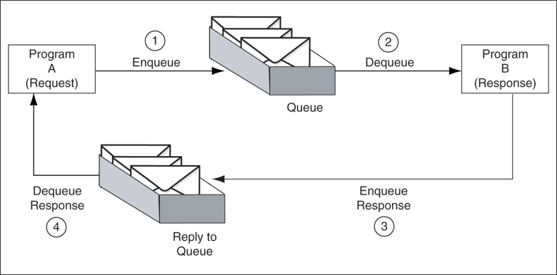
To enqueue is to put a message in a queue whereas to dequeue is to get a message from a queue, as shown in Figure 10-1.
-
Request/Response
In a request/response interaction, a program sends a message to another program asking for a reply. The request message contains information about where the reply should be sent. The receiving program sends a reply message in response to the request message. The request/response interaction is shown in Figure 10-2.
For more information about the interaction scenarios supported by the Oracle MQ Series Adapter, see Dequeue Message.
10.1.1 MQ Series Concepts
Messaging and Queuing Series (MQ Series) is a set of products and standards developed by IBM. MQ Series provides a queuing infrastructure that provides guaranteed message delivery, security, and priority-based messaging.
Note:
The Oracle MQ Series Adapter is certified on IBM MQ V7.5.
The communication process between an MQ Series application and an MQ Series server is shown in Figure 10-3. An MQ Series client enables an application to connect to a queue manager on a remote computer.
Figure 10-3 The MQ Series Communication Process

Description of "Figure 10-3 The MQ Series Communication Process"
Every queue in MQ Series belongs to a queue manager. A queue manager has a unique name and provides messaging and queuing services to applications through a Message Queue Interface (MQI) channel. A queue manager also provides access to the queues created on it and transfers messages to other queue managers through message channels.
In MQ Series, data is sent in the form of messages. The sending application constructs a message and sends it to a queue by using API calls. The message remains in the queue until the receiving application is ready to receive it. The receiving application gets the messages from the queue by using API calls.
For sending messages to a remote queue, the remote queue definition must be defined locally. The remote queue definition consists of the destination queue name and the transmission queue name.
Figure 10-4 displays the message structure of an MQ Series message.
An MQ Series message consists of the following parts, as shown in Figure 10-4:
-
Message Header
The message header contains information such as unique message ID, message type, message priority, and routing information. Every MQ Series message must have a message header.
-
Optional Header
The optional header is required for communication with specific applications, such as the CICS application.
For more information, see Integration with CICS.
-
Application Data
This contains the actual data, for example, a record from an indexed or flat file or a row or column from a DB2 table.
Note:
Important troubleshooting: Inbound MQ processes must not use the same queue unless mutually exclusive MessageSelectors have been defined for each inbound process. If a MessageSelector is not defined, or the selection criteria for two or more inbound process overlap, issues might occur due to one process reading messages that are meant for another process.
Also, the following message found in the MQ Series Adapter log is not an error. It means that no message is available on the queue.
com.ibm.mq.MQException: MQJE001: Completion Code 2, Reason 2033 at com.ibm.mq.MQQueue.get(MQQueue.java:1033)
10.2 Introduction to Native Oracle MQ Series Adapter
Oracle BPEL Process Manager and Oracle Mediator and Mediator include the Oracle MQ Series Adapter. The Oracle MQ Series Adapter enables applications to connect to MQ Series queue managers and place MQ Series messages on queues or to remove MQ Series messages from queues.
This section contains the following topics:
Note:
To prevent the MQ Series Adapter's test connection thread from being blocked forever, ensure that the KeepAlive option is enabled on the MQ Series queue manager. See IBM MQ documentation for more details on how to set the KeepAlive option.
10.2.1 The Need for Oracle MQ Series Adapter
The Oracle MQ Series Adapter provides all native MQ Series functionalities. Although you can configure the Oracle JCA Adapter for JMS (Oracle JMS Adapter) with MQ Series provider, it provides only the JMS functionalities provided by MQ Series and not the native MQ Series functionalities. The following list explains the advantages of Oracle MQ Series Adapter over the Oracle JMS Adapter:
-
The Oracle MQ Series Adapter supports Positive Action Notification (PAN) and Negative Action Notification (NAN).
-
The Oracle MQ Series Adapter supports report messages such as confirmation on delivery, confirmation on arrival, exception report, and expiry report.
-
The Oracle MQ Series Adapter supports sending unwanted or corrupted messages to a dead-letter queue.
-
The Oracle MQ Series Adapter provides advanced filter options, such as filtering message belonging to a group.
-
The Oracle MQ Series Adapter is faster and easier to use.
Note:
The MQ Series version that the Oracle MQ Series Adapter is certified is 7.5 version, both on Windows and Linux.
10.2.2 Oracle MQ Series Adapter Integration with Oracle BPEL Process Manager and Oracle Mediator
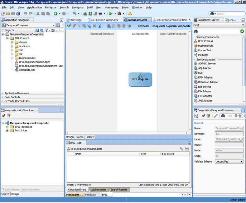
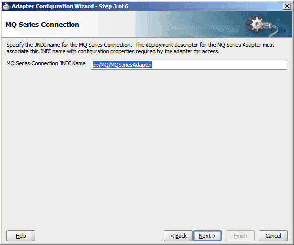
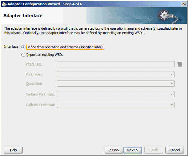
The Oracle MQ Series Adapter is automatically integrated with Oracle BPEL Process Manager and Oracle Mediator. When you create a partner link or an MQ adapter service in Oracle JDeveloper (JDeveloper), the Adapter Configuration Wizard is started.
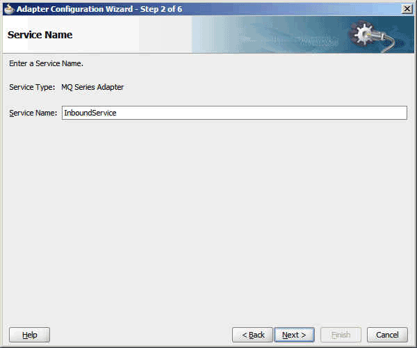
This wizard enables you to select and configure the Oracle MQ Series Adapter or other Oracle JCA Adapters. The Adapter Configuration Wizard then prompts you to enter a service name, as shown in Figure 10-5.
When the configuration is complete, a WSDL file of the same name is created in the Application Navigator section of JDeveloper. This WSDL file contains the configuration information you specify with the Adapter Configuration Wizard.
The Operations page of the Adapter Configuration Wizard prompts you to select an operation to perform. Based on your selection, different Adapter Configuration Wizard pages appear and prompt you for configuration information.
Table 10-1 lists the available operations and provides references to sections that describe the information about these operations.
Table 10-1 Supported Operations for Oracle BPEL Process Manager
| Operation | See Section... |
|---|---|
|
Enqueue Message |
|
|
Dequeue Message |
|
|
Request-Response |
Asynchronous Request-Response ( As Client) Synchronous Request-Response ( As Server) Asynchronous Request-Response ( As Server) Synchronous Request-Response ( As Server) Synchronous Request-Response ( As Client) |
|
Outbound Dequeue |
10.2.3 Oracle MQ Series Adapter Integration with Mediator
The Oracle MQ Series Adapter is automatically integrated with Mediator. When you create an MQ adapter service in JDeveloper Mediator Designer, the Adapter Configuration Wizard is started.
This wizard enables you to select and configure the Oracle MQ Series Adapter. When the configuration is complete, a WSDL file of the same name is created in the Application Navigator section of JDeveloper. This WSDL file contains the configuration information you specify in the Adapter Configuration Wizard.
The Operations page of the Adapter Configuration Wizard prompts you to select an operation to perform. Based on your selection, different Adapter Configuration Wizard pages appear and prompt you for configuration information. Table 10-2 lists the available operations and provides references to sections that describe the configuration information you must provide.
Table 10-2 Supported Operations for Oracle Mediator
| Operation | See Section... |
|---|---|
|
Enqueue Message |
|
|
Dequeue Message |
|
|
Request-Response |
Synchronous Request-Response ( As Server) |
|
Outbound Dequeue |
10.3 Oracle MQ Series Adapter Features
This section explains the following features of the Oracle MQ Series Adapter:
10.3.1 RFH Version 2 (RFH2) Header
The RFH2 header is an extensible header. The RFH2 header enables you to add more header properties to the payload. The RFH2 header carries JMS-specific data that is associated with the message content and can also carry additional information that is not directly associated with JMS.
The RFH2 header consists of two parts, a fixed portion and a variable portion. There can be multiple RFH2 headers in the same message.
10.3.1.1 Fixed Portion
The fixed portion is modeled on the standard MQ header pattern and consists of the following fields:
StrucId (MQCHAR4)
Structure identifier.
Must be MQRFH_STRUC_ID (value: "RFH ") (initial value).
MQRFH_STRUC_ID_ARRAY (value: "R","F","H"," ") is also defined in the usual way.
Version (MQLONG)
Structure version number.
Must be MQRFH_VERSION_2 (value: 2) (initial value).
StrucLength (MQLONG)
Total length of MQRFH2, including the NameValueData fields.
The value set into StrucLength must be a multiple of 4 (the data in the NameValueData fields may be padded with space characters to achieve this).
Encoding (MQLONG)
Data encoding.
Encoding of any numeric data in the portion of the message following MQRFH2 (the next header, or the message data following this header).
CodedCharSetId (MQLONG)
Coded character set identifier.
Representation of any character data in the portion of the message following MQRFH2 (the next header, or the message data following this header).
Format (MQCHAR8)
Format name.
Format name for the portion of the message following MQRFH2.
Flags (MQLONG)
Flags.
MQRFH_NO_FLAGS =0. No flags set.
NameValueCCSID (MQLONG)
The coded character set identifier (CCSID) for the NameValueData character strings contained in this header. The NameValueData may be coded in a character set that differs from the other character strings that are contained in the header (StrucID and Format).
If the NameValueCCSID field is a 2-byte Unicode CCSID (1200, 13488, or 17584), then the byte order of the Unicode CCSID is the same as the byte ordering of the numeric fields in MQRFH2. (For example, Version, StrucLength, and NameValueCCSID itself.)
The NameValueCCSID field may take only values from Table 10-3:
Table 10-3 Possible Values for NameValueCCSID Field
| Value | Meaning |
|---|---|
|
1200 |
UCS2 open-ended |
|
1208 |
UTF8 |
|
13488 |
UCS2 2.0 subset |
|
17584 |
UCS2 2.1 subset (includes the Euro symbol) |
10.3.1.2 Variable Portion
The variable portion follows the fixed portion. The variable portion contains a variable number of MQRFH2 folders. Each folder can occur multiple times in the same RFH2 header. Other folders such as mqext, mq_usr, mqps and others. can also be part of the RFH2 header. For more information, refer to the IBM documentation regarding MQ RFH2 headers.
The related properties are grouped together. The MQRFH2 header can contain the following message service folders:
The <mcd> folder
This contains properties that describe the shape or format of the message. For example, the Msd property identifies the message as being Text, Bytes, Stream. Map, Object, or Null. This folder is always present in JMS MQRFH2.
The <jms> folder
This is used to transport JMS header fields, and JMSX properties that cannot be fully expressed in the MQMD. This folder is always present in a JMS MQRFH2.
The <usr> folder
This is used to transport any application-defined properties associated with the message. This folder is only present if the application has set some application-defined properties.
The <psc> folder
This is used to convey publish/subscribe command messages to the broker. Only one psc folder is allowed in the NameValueData field.
The <pscr> folder
This is used to contain information from the broker, in response to publish/subscribe command messages. Only one pscr folder is present in a response message.
Table 10-4 shows a full list of property names.
Table 10-4 MQRFH2 Folders and Properties Used by JMS
| JMS Field Name | Java Type | MQRFH2 Folder name | Property Name | Type/values |
|---|---|---|---|---|
|
JMSDestination |
Destination |
jms |
Dst |
string |
|
JMSExpiration |
long |
jms |
Exp |
i8 |
|
JMSPriority |
int |
jms |
Pri |
i4 |
|
JMSDeliveryMode |
int |
jms |
Dlv |
i4 |
|
JMSCorrelationID |
String |
jms |
Cid |
string |
|
JMSReplyTo |
Destination |
jms |
Rto |
string |
|
JMSTimestamp |
long |
jms |
Tms |
i8 |
|
JMSType |
String |
mcd |
Type, Set, Fmt |
string |
|
JMSXGroupID |
String |
jms |
Gid |
string |
|
JMSXGroupSeq |
int |
jms |
Seq |
i4 |
|
xxx (User Defined) |
Any |
usr |
xxx |
any |
|
- |
- |
mcd |
Msd |
jms_none |
|
- |
- |
mcd |
Msd |
jms_text |
|
- |
- |
mcd |
Msd |
jms_bytes |
|
- |
- |
mcd |
Msd |
jms_map |
|
- |
- |
mcd |
Msd |
jms_stream |
|
- |
- |
mcd |
Msd |
jms_object |
The syntax used to express the properties in the variable portion is as follows:
NameValueLength (MQLONG)
Length, in bytes, of the NameValueData string that immediately follows this length field. It does not include its own length. The value set into NameValueLength is always a multiple of 4. The NameValueData field is padded with space characters to achieve this.
NameValueData (MQCHARn)
A single character string, whose length in bytes is given by the preceding NameValueLength field. It contains a folder holding a sequence of properties. Each property is a name/type/value triplet, contained within an XML element whose name is the folder name, as follows:
<foldername> triplet1 triplet2 ..... tripletn </foldername>
10.3.2 SSL Enabling
Secure Sockets Layer (SSL) is a protocol for transmitting encrypted data over the Internet or an internal network. SSL works by using public and private keys to encrypt data that is transferred over the SSL connection. Data that has been encrypted with a public key can be decrypted only with the corresponding private key. Conversely, data that has been encrypted with a private key can be decrypted only with the corresponding public key.
MQ Series supports secure communication, with MQ Series clients using SSL. As a part of this functionality, the adapter would provide support to put a message on queue using SSL. To enable Oracle MQ Series Adapter for SSL, the following properties must be provided:
-
SSLEnable: The true/false value for this property means that the Oracle MQ Series Adapter is SSL enabled/disabled.
-
KeyStoreLocation: This is the keystore where Oracle MQ Series Adapter has its private keys. This property is required as the adapter must authenticate itself to the MQ Series server.
-
KeyStorePassword: This password is required to access keystore.
-
TrustStoreLocation: This is the location where the adapter keeps its trusted certificates information. This information is required when an adapter must authenticate to the MQ Series server.
-
Protocol: Key Management Algorithm.
-
KeyStoreProviderName: The name of the keystore provider.
-
KeyStoreType: Type of the key store.
-
KeyStoreAlgorithm: Algorithm used by the key store.
-
CipherSuite: Set CipherSuite to the name matching the CipherSpec set on the
SVRCONNchannel. If set to null (default), then no SSL encryption is performed. -
SSLPeerName: A distinguished name pattern. If CipherSuite is set, then you can use this variable to ensure that the correct queue manager is used. If set to null (default), then the DN of the queue manager is not checked. This variable is ignored if
sslCipherSuiteis null.
10.3.3 XA Transactions
Note:
According to IBM, the use of WebSphere MQ Java Transaction API (JTA) by a non WebSphere MQ transaction manager is not supported. IBM recommends that the WebSphere MQ JMS API be used instead in XA transactions. This means that the user must use Oracle JCA Adapter for JMS when XA transactions are required to interact with IBM MQ instead of Oracle JCA Adapter for MQ Series. If the MQ adapter is used for XA transaction, the adapter might encounter an error when it needs to roll back an XA transaction. The user will then need to manually resolve any in-doubt transactions.The Oracle MQ Series Adapter enables transaction support, which along with the inherent data processing, ensures that each modification has a clearly defined outcome, resulting in either success or failure, thus preventing potential corruption of data, executes independently from other changes, and, after completion, leaves underlying data in the same state until another transaction takes place.
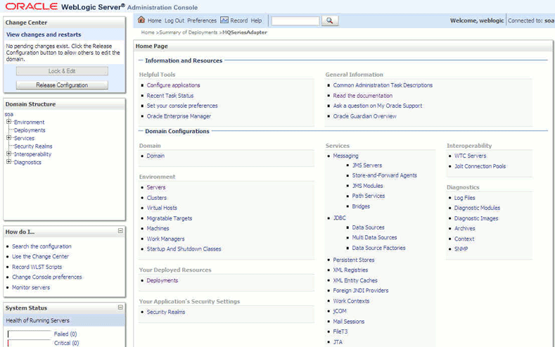
The Oracle MQ Series Adapter supports both inbound and outbound XA transaction. You must set the XATransaction property in the Oracle WebLogic Server Administration Console to enable the XA transaction. To enable XA transaction, perform the following steps:
-
Log in to the Oracle WebLogic Server Administration Console using your password credentials.
-
Under Domain Structure, in the left pane, click Deployments. The Summary of Deployments page is displayed.
-
Click MQSeriesAdapter. The Settings of MQSeriesAdapter page is displayed.
-
Click the Configuration tab. The Configuration submenu options are displayed.
-
Click Outbound Connection Pools. The Outbound Connection Pool Configuration Table is displayed.
-
Click the + icon next to javax.resource.cci.ConnectionFactory and select eis/MQ/MQAdapter. The Outbound Connection Properties page is displayed.
Note:
Click Lock & Edit to enable the options in the console.
-
Select the XATransaction option and click the Property Value row at the end of the XATransaction.
-
Enter
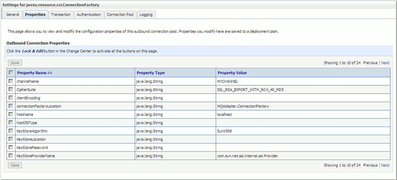
truein the text field, as shown in Figure 10-6, and click Save.Figure 10-6 Outbound Connection Properties Page

Description of "Figure 10-6 Outbound Connection Properties Page" -
Click the Transaction tab. The Settings for
javax.resource.cci.ConnectionFactorypage is displayed. -
Select XA Transaction from the Transaction Support list.
-
Click Save to save your settings. The Save Deployment Plan Assistant page is displayed.
-
Click OK.
You have successfully enabled XA transaction for the Oracle MQ Series Adapter.
In order to use the XA transaction feature for MQ Series with BPEL for synchronous inbound request-reply scenario, you must set the bpel.config.transaction parameter to required. If this parameter is not set, then it causes the transaction to split at the BPEL boundary and MQ returns MQRC_SYNCPOINT_NOT_AVAILABLE error code.
<property name="bpel.config.transaction">required
</property>
10.3.3.1 XA Recovery
In a scenario involving fail over, such as when the prepare phase completes successfully before a middleware fails, messages must be recovered within the adapter without restarting the MQSeries server. You must manually resolve the in-doubt transactions.
To view all in-doubt transactions for a Queue Manager, you must execute the following command at the command prompt:
dspmqtrn -m[ourQueueManager]
To backout the messages, use the following command:
rsvmqtrn -m[ourQueueManager] -b [Transaction],[Number]
To commit the messages, use the following command :
rsvmqtrn -m[ourQueueManager] -c [Transaction],[Number]
Note:
You can use the[Transaction] and [Number] from the output of the dspmqtrn command.
10.3.4 High Availability
The Oracle MQ Series Adapter supports the high availability feature for the active-active topology with Oracle BPEL Process Manager (Oracle BPEL PM) and Mediator service engines. It supports this feature for both inbound and outbound operations.
10.3.4.1 Prerequisites for High Availability
Before you configure the Oracle MQ Series Adapter for high availability, you must ensure that the following prerequisites are met:
-
Clustered processes must use the same queue.
-
Retries should be configured either at the binding level or by using fault policies to ensure that any intermittent errors can be resolved automatically.
10.3.4.2 High Availability in Inbound/Outbound Operations
The Oracle MQ Series Adapter must ensure that it participates in the XA transaction. For more information about the XA transaction, see XA Transactions.
10.3.5 Scalability
The Oracle MQ Series Adapter supports the scalability feature for inbound operations only. Oracle MQ Series Adapter provides the parameter to control the number of threads that dequeue the messages from the inbound queue.You must specify the following property in the.jca file:
InboundThreadCount='N'
where, N is the number of threads to span to dequeue the messages from the inbound queue. The default setting is 2.
The Oracle MQ adapter creates the back-endconnections at deployment time, that is, at that time the adapter endpoint starts polling. You can have the application server prewarm the connection pool, which would provide a small marginal advantage, although connection creation does not otherwise delay the overall deployment task itself.
The example syntax for using InboundThreadCount in the .jca file is:
<adapter-config name="ExpressDeathEventListener" adapter="MQSeriesAdapter" wsdlLocation="ExpressDeathEventListener.wsdl" <xmlns="http://platform.integration.oracle/blocks/adapter/fw/metadata">
  <connection-factory location="eis/MQ/MQAdapter" adapterRef=""/>
   <endpoint-activation portType="Dequeue_ptt" operation="Dequeue"           UITransmissionPrimitive="Dequeue">
   <activation-spec className="oracle.tip.adapter.mq.inbound.ActivationSpecImpl">
      <property name="QueueName" value="BPMPOC_EXPCLAIMQ"/>
      <property name="InboundThreadCount" value="10"/>
   </activation-spec>
  </endpoint-activation>
</adapter-config>
10.3.6 Securing Enterprise Information System Credentials
The Oracle MQ Series Adapter supports securing of the Enterprise Information System (EIS) credentials such as the user name and password, whenever it establishes an outbound connection with EIS. You can secure the user name and password for Oracle MQ Series Adapter by using Oracle WebLogic Server container-managed sign-on.
For more information, see Securing Enterprise Information System Credentials.
10.3.7 Fault Policy
A fault policy file defines fault conditions and their corresponding fault recovery actions. Each fault condition specifies a particular fault or group of faults, which it attempts to handle, and the corresponding action for it. A set of actions is identified by an ID in the fault policy file.
The Oracle MQ Series Adapter supports defining rejection handlers by using fault policies.
For more information about fault policies, see Configuring Rejection Handlers.
10.3.8 Inbound Rejection Handler
The Oracle MQ Series Adapter supports inbound message rejection handling. You can configure the message rejection handler to process translation errors, take corrective action.
For more information about rejection handlers, Configuring Rejection Handlers.
10.3.9 Retry Mechanism
The Oracle MQ Series Adapter supports the following two mechanisms for inbound retry:
The JCA inbound retry mechanism is commonly used by all adapters, in general, whereas the message backout queue mechanism is used only by the Oracle MQ Series Adapter. If you specify the BackoutQueueName property in the .jca file, only then the Oracle MQ Series Adapter uses the message backout queue mechanism to retry. By default, the JCA inbound retry mechanism is used for retry.
Note:
Both these methods of retry in the Oracle MQ Series Adapter are mutually exclusive operations; the adapter uses one mechanism at a time. If you specify both options, then the Backout Queue option takes precedence.
10.3.9.1 JCA Inbound Retry Mechanism
The Oracle MQ Series Adapter supports a pull model for connecting to the back-end application for receiving events. Connection-related issues are considered recoverable and most inbound adapters keep retrying until the adapters are able to establish connection with the EIS.
In case of Oracle MQ Series Adapter, a message not being able to put to a queue is also retriable.
For more information about retry mechanism, see Error Handling.
10.3.9.2 Message Backout Queue
Backout Queue is a queue for putting rejected messages from an inbound queue. The inbound adapter checks for the backout count of the messages and if this count exceeds the MaximumBcakoutCount value, then the adapter puts the messages to the specified Backout Queue. This mechanism is used by the Oracle MQ Series Adapter to handle inbound retries for the rejected messages.
If you specify the BackoutQueueName property in the .jca file, then Oracle MQ Series Adapter uses the message backout count for retries. You can specify the maximum retries using the MaximumBackoutCount property. The default value for this property is infinite. If you do not specify the MaximumBackoutCount value along with the BackoutQueueName, then the adapter retries infinitely. The adapter does not consider JCA retries (specified in composite.xml) when the BackOut Queue properties are specified.
The BackoutRetries property must be set to specify the number of retries for delivering the message to the Backout Queue with retry interval set using the BackoutRetryInterval property. The default value for BackoutRetries is 3 and BackoutInterval is 5 sec.
If a message gets rejected even after the MaximumBackoutCount value is reached, then the adapter puts the message to Backout Queue. If Oracle MQ Series Adapter is cannot put the message to Backout Queue, then the adapter tries till the BackoutRetries count with the BackoutInterval time delay. If even after the BackoutRetries the adapter cannot put the message to Backout Queue, then the adapter deactivates the endpoint.
You must also specify the name of the Queue Manager of the Backout Queue in the BackoutQueueManagerName property. You must not use this property if the BackoutQueue resides on the inbound queue QueueManager.
Note:
When using the Backout Queue, consider the following:
-
The Backout Queue options cannot be used for translation failures.
-
In cases where both JCA and BackOut retries are specified, the BackOut retries takes precedence.
For more information about configuring Backout Queues, see Configuring a Backout Queue.
10.4 Oracle MQ Series Adapter Concepts
This section explains the following concepts of the Oracle MQ Series Adapter:
10.4.1 Messaging Scenarios
The Oracle MQ Series Adapter supports the following messaging scenarios:
10.4.1.1 Enqueue Message
In this scenario, the Oracle MQ Series Adapter connects to a specific queue managed by a queue manager and then writes the message to the queue. For outbound messages sent from Oracle BPEL PM or Mediator, the Oracle MQ Series Adapter performs the following operations:
-
Receives message from Oracle BPEL PM or Mediator.
-
Formats the XML content as specified at design time.
-
Sets the properties of the message, such as priority, expiry, message type, and persistence. These properties are based on the selections that you made in the Adapter Configuration Wizard.
For more information about message properties, see Messages Types.
-
Sends the message to the queue specified at design time in the Adapter Configuration Wizard.
Figure 10-7 displays the operation type that you must select in the Adapter Configuration Wizard.
Figure 10-7 The Adapter Configuration Wizard: Produce Message Selection
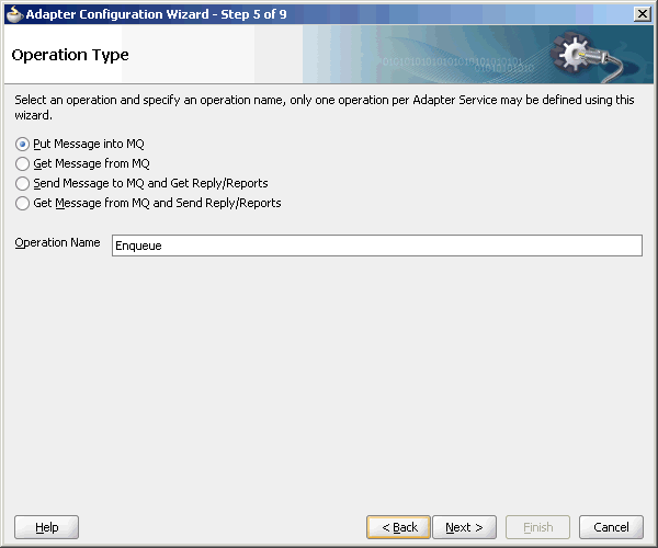
Description of "Figure 10-7 The Adapter Configuration Wizard: Produce Message Selection"
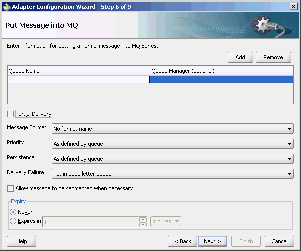
The page that appears after selecting the Put Message into MQ operation type is shown in Figure 10-8.
You can specify the following properties in this page:
-
Queue Name: The name of the queue on which the Oracle MQ Series Adapter enqueues the message. This is a mandatory field.
-
Queue Manager: The name of the queue manager to which the queue belongs. This field is optional and is necessary when enqueuing message to a remote queue.
-
Partial Delivery: This is applicable only when you specify multiple queues for outbound operation, which is also known as the Distribution List scenario. Partial Delivery takes either
trueorfalse. If assignedtrue, then even if the delivery of message fails for some queues, it would still go and put the message to the rest of the queues specified in the distribution list. If assignedfalse, it means even if one message fails, then the message is not put to any queue. -
Message Format: The format of the message.
Note:
When enqueuing a message, ensure that the various mandatory values, required for a specific format, are specified correctly.
-
Priority: The priority of the message, ranging from 0 (low) to 9 (high).
-
Persistence: The persistence of the message. You can also specify the persistence of the message to be taken from the default persistence attribute, as defined by the destination queue.
-
Delivery Failure: If the delivery of message fails, then either it can be put to a dead letter queue or it can be discarded.
-
Allow Messages to Be Segmented When Necessary: This is applicable to a message that is big enough for the queue to accommodate. In that case, if you have specified that it has to be segmented, then the single message can be broken into that many bytes the queue can take, which results in multiple messages.
-
Expiry: The expiry time of the message. The message is discarded after the expiry time has elapsed.
For more information about these properties, see Message Properties.
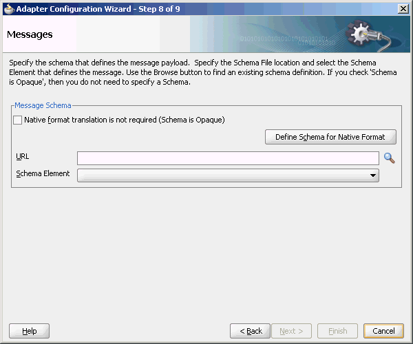
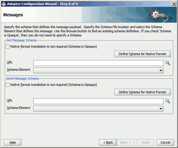
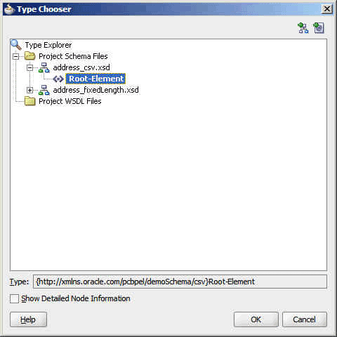
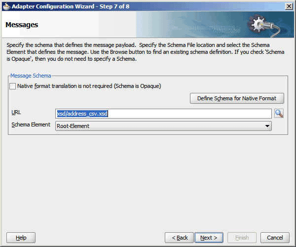
The next Adapter Configuration Wizard page that appears is the Messages page, as shown in Figure 10-9. This page enables you to select the XML Schema Definition (XSD) file for translation.
If native format translation is not required (for example, a JPG or GIF image is being processed), then select the Native format translation is not required check box. The file is passed through in base-64 encoding.
XSD files are required for translation. To define a new schema or convert an existing data type description (DTD) or COBOL Copybook, select Define Schema for Native Format. This starts the Native Format Builder wizard. This wizard guides you through the creation of a native schema file from file formats, such as delimited by special characters, comma-delimited value (CSV), fixed-length, DTD, and COBOL Copybook. After the native schema file is created, you are returned to this Messages page with the Schema File URL and Schema Element fields filled in.
For more information, see Creating Native Schema Files with the Native Format Builder Wizard.
Note:
Ensure that the schema you specify includes a namespace. If your schema does not have a namespace, an error message appears.
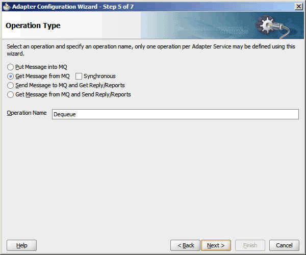
10.4.1.2 Dequeue Message
In this scenario, the Oracle MQ Series Adapter connects to a specific queue managed by a queue manager and then removes the message from the queue. For inbound messages sent to Oracle BPEL PM or Mediator, the Oracle MQ Series Adapter performs the following operations:
-
Connects to the queue specified at design time.
-
Dequeues the message from the queue when a message arrives.
-
Reads and translates the message based on the translation logic defined at design time.
-
Publishes the message as an XML message to Oracle BPEL PM or Mediator.
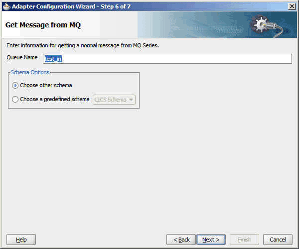
Figure 10-10 displays the operation type that you must select in the Adapter Configuration Wizard.
Figure 10-10 The Adapter Configuration Wizard: Consume Message Selection
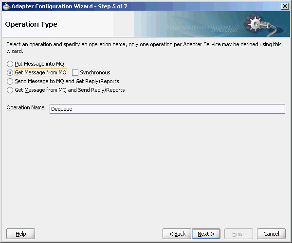
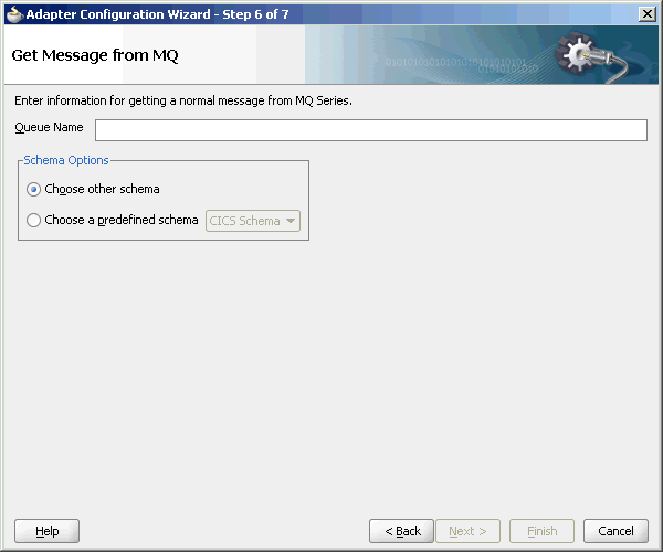
Description of "Figure 10-10 The Adapter Configuration Wizard: Consume Message Selection"The page that appears after selecting the Get Message from MQ operation type is shown in Figure 10-11.
You can specify the following properties in this page:
-
Queue Name: The name of the queue from which the Oracle MQ Series Adapter dequeues the message. This is a mandatory field.
-
Schema Options: This option enables you to specify the schema for the message to be dequeued.
-
Choose Other Schema: This option enables you to choose your schema for the message to be dequeued.
-
Choose a Predefined Schema: This option enables you to choose a readymade schema that the adapter provides.
-
The next Adapter Configuration Wizard that appears is the Messages page, as shown in Figure 10-9. This page enables you to select the XSD schema file for translation.
As with specifying the schema for the produce message operation, you can perform the following tasks in this page:
-
Specify if native format translation is not required.
-
Select the XSD schema file for translation.
-
Start the Native Format Builder wizard to create an XSD file from file formats such as CSV, fixed-length, DTD, and COBOL Copybook.
For more information about the Messages page, see Enqueue Message.
-
10.4.1.3 Asynchronous Request-Response (Oracle BPEL PM As Client)
In this scenario, the Oracle BPEL PM sends a request message and receives the corresponding response using a non-initiating receive activity. The invoke activity initiates the outbound invocation of the adapter to send the request. The Oracle MQ Series Adapter performs the following operations:
-
Receives message from Oracle BPEL PM.
-
Formats the XML content as specified at design time in the Adapter Configuration Wizard.
-
Sets properties and a correlation schema on the request message.
-
Sends the message to the queue specified at design time. The third-party application receives the message, processes it, generates the response, and then enqueues the response message to the
replyToqueue specified in the request message. The Correlation ID and Message ID of the response message are generated based on the correlation schema specified in the request message. -
The Oracle MQ Series Adapter dequeues the message from the
replyToqueue. -
Sends the response to the non-initiating receive activity of Mediator. To ensure that response is sent to the correct BPEL instance, correlation schemas are used.
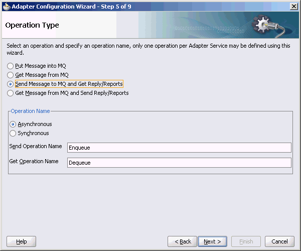
Figure 10-12 displays the operation type that you must select in the Adapter Configuration Wizard.
The page that appears after selecting the Send Message to MQ and Get Reply/Reports operation type is shown in Figure 10-13.
Figure 10-13 Send Message to MQ and Get Reply/Reports Page
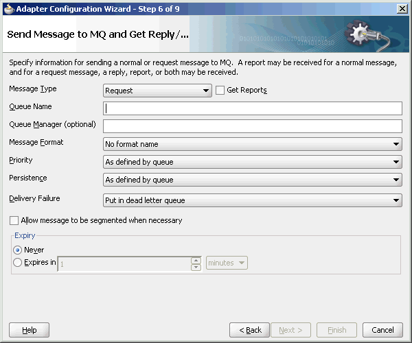
Description of "Figure 10-13 Send Message to MQ and Get Reply/Reports Page"
You can specify the following properties in this page:
-
Message Type: The type of the message. You can either send a normal message or a request message.
-
Get Reports: Select this option if you want any kind of report. You can specify the type of report in the next page, as shown in Figure 10-14.
-
Queue Name: The name of the queue to which the Oracle MQ Series Adapter enqueues the message. This is a mandatory field.
-
Queue Manager: The name of the queue manager to which the queue belongs. This field is optional.
-
Message Format: The format of the message.
-
Priority: The priority of the message ranging from 0 (low) to 9 (high).
-
Persistence: The persistence of the message. You can also specify the persistence of the message to be taken from the default persistence attribute, as defined by the destination queue.
-
Delivery Failure: If the delivery of the message fails, then either it can be put to a dead letter queue or it can be discarded.
-
Allow Messages to Be Segmented When Necessary: This is applicable to a message that is big enough for the queue to accommodate. In that case, if you have specified that it has to be segmented, then the single message can be broken into that many bytes the queue can take, which results in multiple messages.
-
Expiry: The expiry time of the message. The message is discarded after the expiry time has elapsed.
For more information about these properties, see Message Properties and Report Messages.
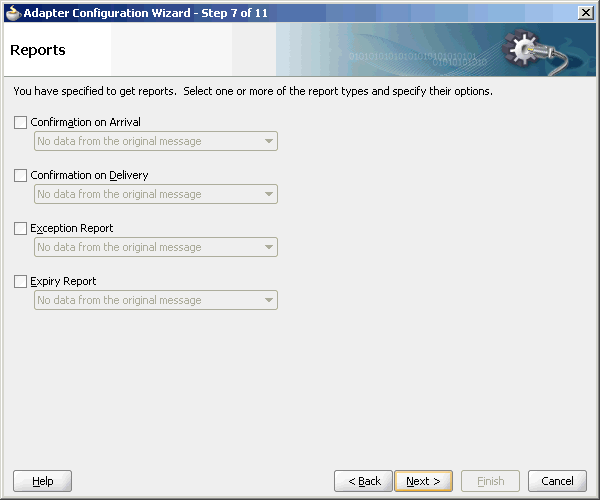
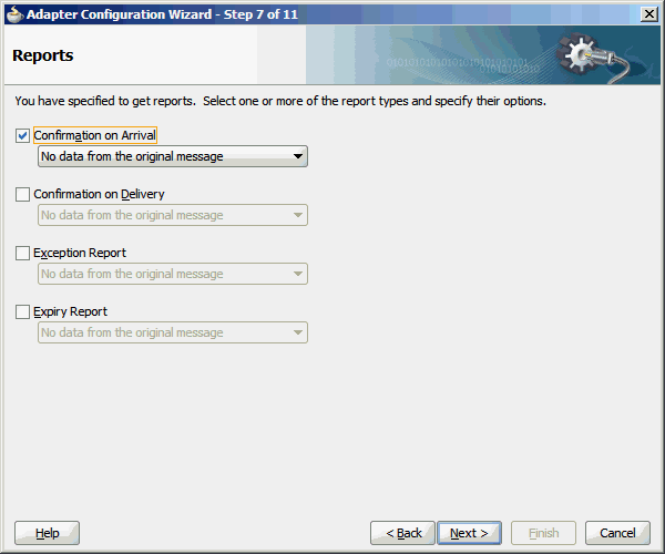
The page that is displayed when you click Next in the Send Message to MQ and Get Reply/Reports page can be a Reports page (shown in Figure 10-14) or a Response page (shown in Figure 10-15).
The Reports page, shown in Figure 10-14, is displayed only if you have selected the Get Reports option in the Send Message to MQ and Get Reply/Reports page, as shown in Figure 10-13.
You can select the following types of reports in this page:
-
Confirmation on Arrival
-
Confirmation on Delivery
-
Exception Report
-
Expiry Report
For information about these report types, see Report Messages.
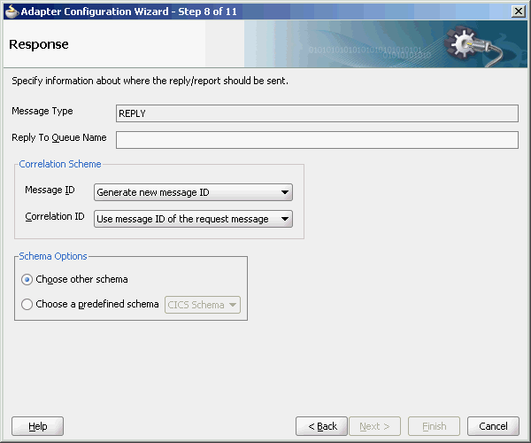
The Response page shown in Figure 10-15 is displayed when you click Next in the Reports page.
You can specify the following properties in the Response page:
-
Reply to Queue Name: The name of the reply queue name.
-
Correlation Scheme: The correlation schema that is necessary for the Oracle MQ Series Adapter.
For information about correlation schemas, see Correlation Schemas.
-
Schema Options: This option enables you to specify the schema for the message to be dequeued.
-
Choose Other Schema: This option enables you to choose your schema for the message to be dequeued.
-
Choose a Predefined Schema: This option enables you to choose a readymade schema that the adapter provides.
-
Note:
For Oracle MQ Series Adapter in an asynchronous outbound request/reply scenario (in this scenario a request message is put to a queue and the reply for the same is dequeued from the replyToQueue asynchronously), properties are differentiated by an (Enqueue) or (Dequeue) label in Oracle Enterprise Manager Console. . This differentiation is necessary to distinguish the property names for enqueue and dequeue. For example, QueueName(Enqueue) is used for putting a message and QueueName(Dequeue) is used for dequeuing the reply.
When using Oracle Enterprise Manager Console to edit Oracle MQ Series Adapter properties in this scenario, note the following:
-
Because the replyToQueue for the request message is the same from the which the reply must be dequeued, if you change the
ReplyToQueueName(Enqueue)property, you must also change theQueueName(Dequeue)property to the same value. -
Similarly, if you change the
MessageId(Dequeue)property, you must also change theMessageId(Enqueue)property to the same value. -
Similarly, if you change the
CorrelationId(Dequeue)property, you must also change theCorrelationId(Enqueue)property to the same value.
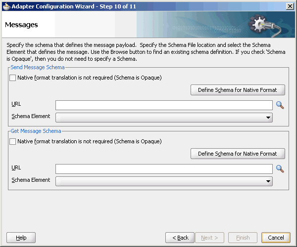
When you click Next in the Response page, a Messages page, shown in Figure 10-16, is displayed. This page enables you to select the XSD schema file for translation for request and as response message.
You can perform the following tasks in this page:
-
Specify if native format translation is not required.
-
Select the XSD schema file for translation.
-
Start the Native Format Builder wizard to create an XSD file from file formats such as CSV, fixed-length, DTD, and COBOL Copybook.
For more information about the Messages page, see Enqueue Message.
In the solicit-request-response scenario, the reply message is expected in the reply queue specified with some correlation scheme that is provided through the request message. This reply queue, which is used by a particular process (BPEL/Mediator), should not be used by any other process.
If the same reply queue is used by some other application, then the message might be picked, irrespective of whether the reply message had the proper correlation or not, and eventually the message becomes lost.
10.4.1.4 Synchronous Request-Response (Oracle BPEL PM As Server)
In this scenario, the Oracle BPEL PM receives a request, processes it, and sends the response synchronously by using a reply activity. The Oracle MQ Series Adapter performs the following operations:
-
Dequeues the request message from the queue when the message arrives.
-
Reads and translates the message based on the translation logic defined at design time.
-
Publishes the message as an XML message to Oracle BPEL PM. The Oracle BPEL PM processes the request and sends the response to the Oracle MQ Series Adapter.
-
Receives the response message from the Oracle BPEL PM.
-
Formats the XML content as specified at design time.
-
Sets the properties of the message such as priority, expiry, message type, and persistence. These properties are based on the selections that you made in the Adapter Configuration Wizard.
-
Sends the message to the queue specified at design time in the Adapter Configuration Wizard.
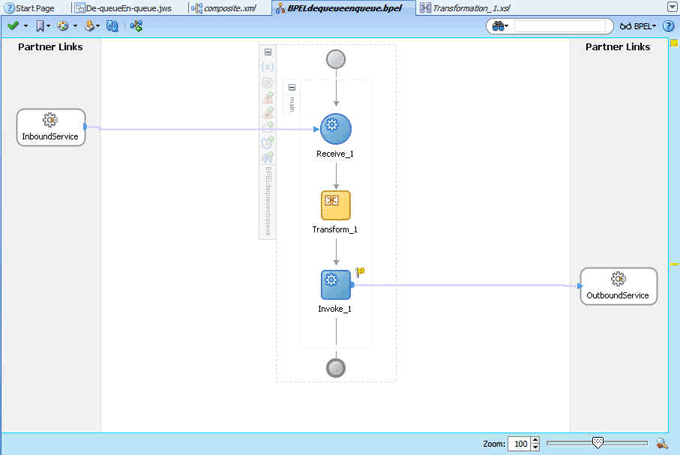
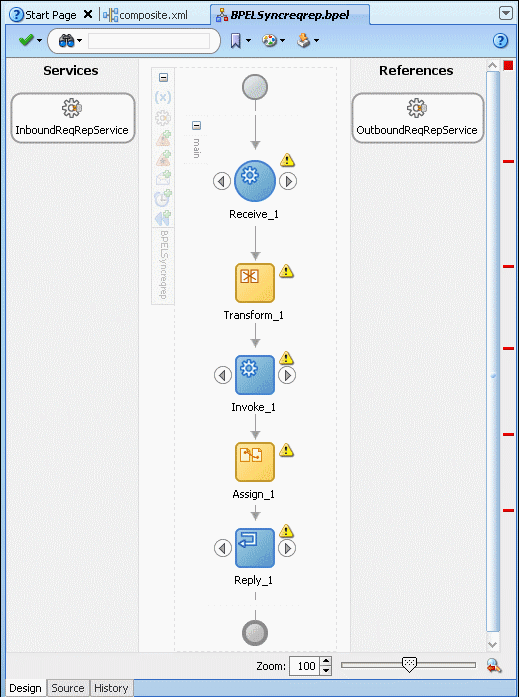
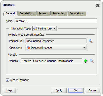
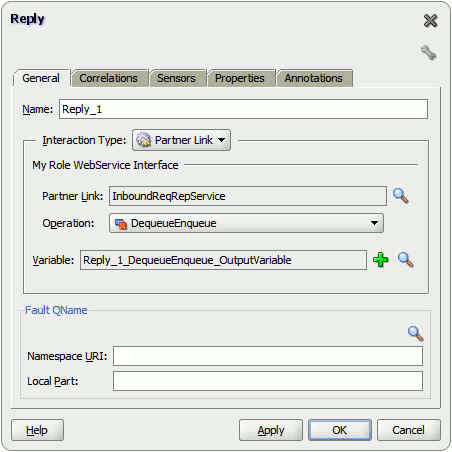
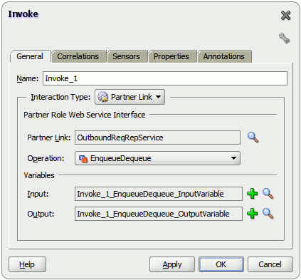
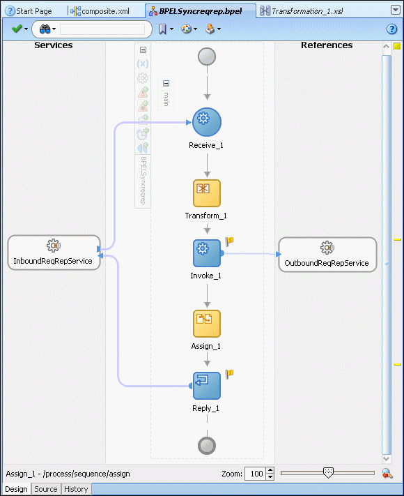
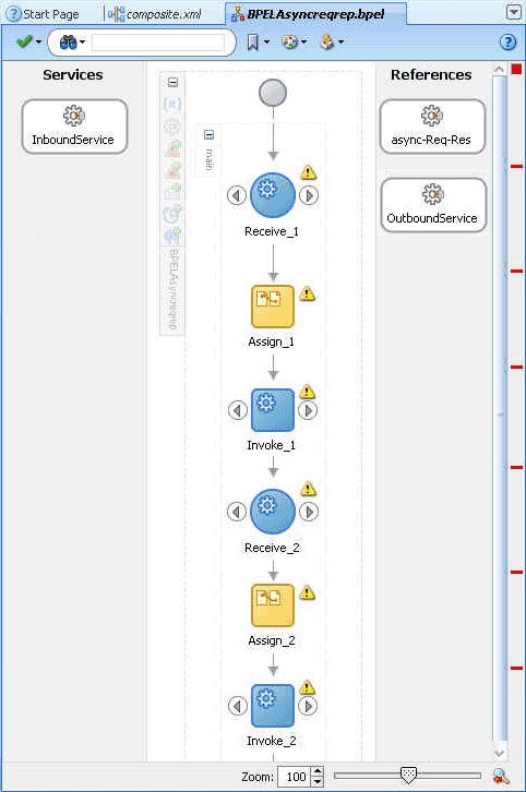
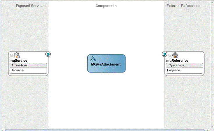
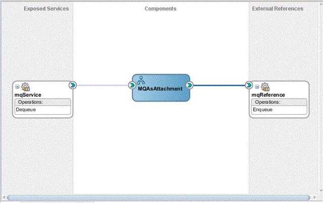
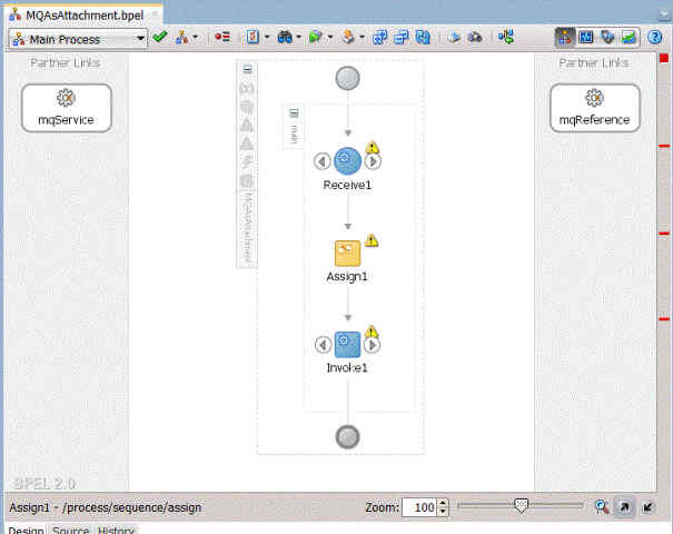
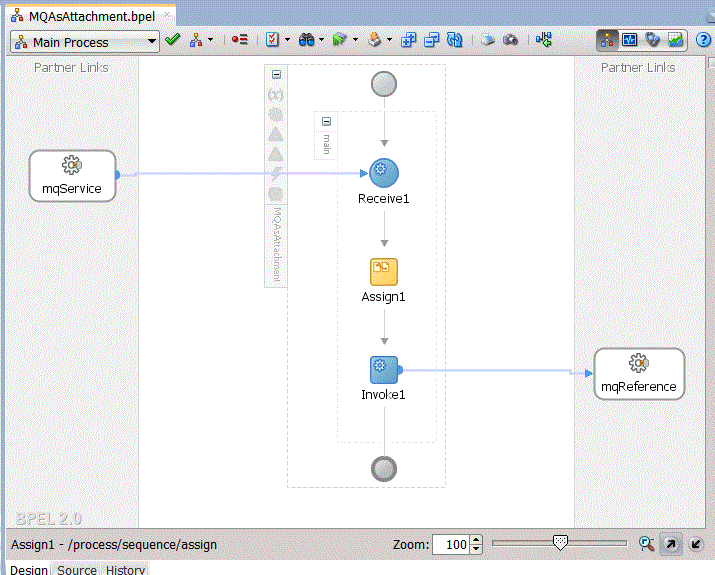
Figure 10-17 shows a sample BPEL process for this scenario.
Figure 10-17 Synchronous Request-Response Oracle BPEL PM As Server Sample
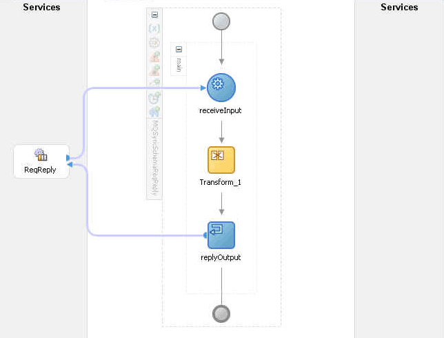
Description of "Figure 10-17 Synchronous Request-Response Oracle BPEL PM As Server Sample"
Figure 10-18 displays the operation type that you must select in the Adapter Configuration Wizard.
Figure 10-18 Operation Type Page Selection for Request-Response Synchronous Interaction
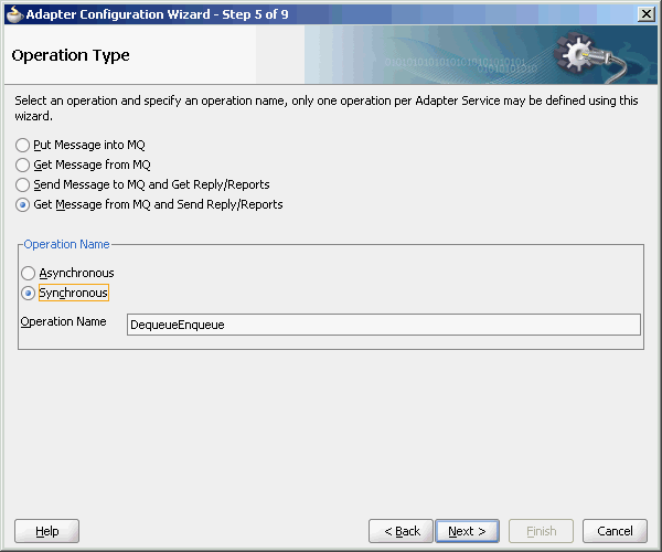
Description of "Figure 10-18 Operation Type Page Selection for Request-Response Synchronous Interaction"
The page that appears after you select the Get Message from MQ and Send Reply/Reports operation type is shown in Figure 10-19. Specify the queue name from which the Oracle MQ Series Adapter dequeues the message in this page.
Figure 10-19 Get Message from MQ and Send Reply/Reports Page
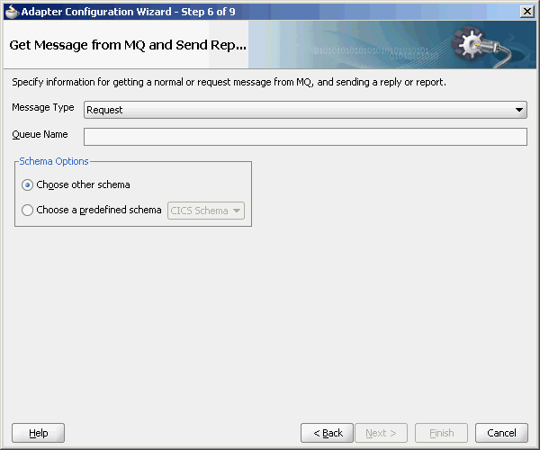
Description of "Figure 10-19 Get Message from MQ and Send Reply/Reports Page"
When you click Next in the Get Message from MQ and send Reply/Reports page, the Response page shown in Figure 10-20 is displayed.
Figure 10-20 Response Page for Synchronous Request-Response
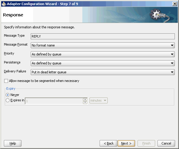
Description of "Figure 10-20 Response Page for Synchronous Request-Response"
You can specify the following properties in the Response page:
-
Message Type: The message type of the message to be dequeued. This option affects the return message type.
-
Message Format: The format of the message.
-
Priority: The priority of the message.
-
Persistence: The persistence of the message. You can also specify the persistence of the message to be taken from the default persistence attribute, as defined by the destination queue.
-
Delivery Failure: If the delivery of the message fails, then either it can be put to a dead letter queue or it can be discarded.
-
Allow Messages to Be Segmented When Necessary: This is applicable to a message that is big enough for the queue to accommodate. In that case, if you have specified that it has to be segmented, then the single message can be broken into that many bytes the queue can take, which results in multiple messages.
-
Expiry: The expiry time of the message.
For more information about these properties, see Message Properties.
Click Next in the Response page, the Messages page is displayed, as shown in Figure 10-16. You can perform the following tasks in this page:
-
Specify if native format translation is not required.
-
Select the XSD schema file for translation.
-
Start the Native Format Builder wizard to create an XSD file from file formats such as CSV, fixed-length, DTD, and COBOL Copybook.
For more information about the Messages page, see Enqueue Message.
10.4.1.5 Asynchronous Request-Response (Oracle BPEL PM As Server)
In Oracle BPEL PM initiated request-response interaction, a BPEL process receives a request as an inbound message, processes it, and then sends the response through an invoke activity. For asynchronous request-reply scenario, the Oracle MQ Series Adapter performs the following operations:
-
Dequeues the message from the queue when a message arrives.
-
Reads and translates the message based on the translation logic defined at design time.
-
Publishes the message as an XML message to Oracle BPEL PM. The Oracle BPEL PM processes the request and sends the response to the Oracle MQ Series Adapter.
-
Receives messages from Oracle BPEL PM.
-
Formats the XML content as specified at design time.
-
Sets the properties of the message, such as priority, expiry, message type, and persistence. These properties are based on the selections that you made in the Adapter Configuration Wizard.
-
Sends the message to the queue specified at design time in the Adapter Configuration Wizard.
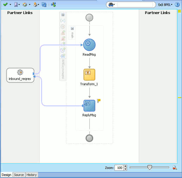
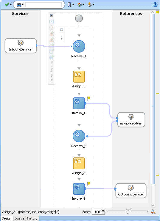
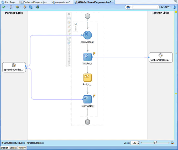
Figure 10-21 shows a sample BPEL process for this scenario.
Figure 10-21 Asynchronous Request-Response Oracle BPEL PM As Server Sample
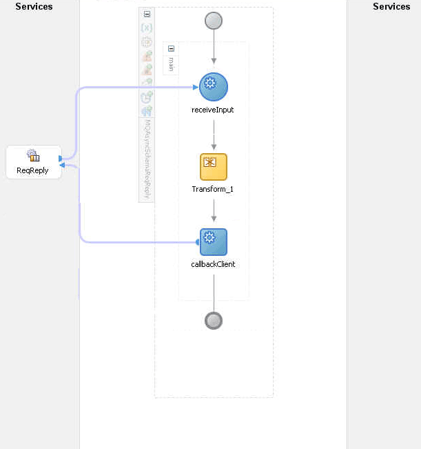
Description of "Figure 10-21 Asynchronous Request-Response Oracle BPEL PM As Server Sample"
Figure 10-22 displays the operation type that you must select in the Adapter Configuration Wizard.
Figure 10-22 Operation Type Page Selection for Request-Response Asynchronous Interaction
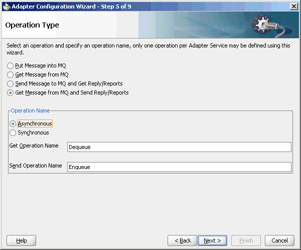
Description of "Figure 10-22 Operation Type Page Selection for Request-Response Asynchronous Interaction"
The page that appears after selecting the Get Message from MQ and send Reply/Reports operation type is shown in Figure 10-19. Specify the queue name from which the Oracle MQ Series Adapter dequeues the message in this page.
When you click Next in the Get Message from MQ and send Reply/Reports page, the Response page shown in Figure 10-20 is displayed.
You can specify the following properties in the Response page:
-
Message Type: The message type of the message to be dequeued. This option affects the return message type.
-
Message Format: The format of the message.
-
Priority: The priority of the message.
-
Persistence: The persistence of the message. You can also specify the persistence of the message to be taken from the default persistence attribute, as defined by the destination queue.
-
Delivery Failure: If the delivery of the message fails, then either it can be put to a dead letter queue or it can be discarded.
-
Allow Messages to Be Segmented When Necessary: This is applicable to a message that is big enough for the queue to accommodate. In that case, if you have specified that it has to be segmented, then the single message can be broken into that many bytes the queue can take, which results in mulitple messages.
-
Expiry: The expiry time of the message.
For more information about these properties, see Message Properties.
The page that is displayed when you click Next in the Get Message to MQ and Send Reply/Reports page is a Response page (shown in Figure 10-23 and Figure 10-24) but with two different set of options.
Figure 10-23 Response Page (Request Message Type Selected)
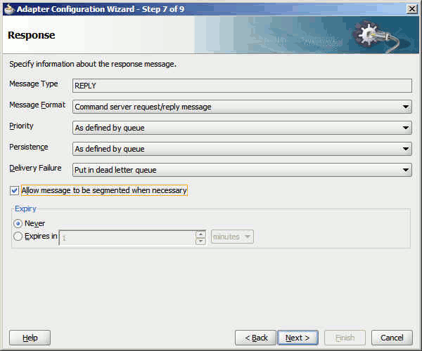
Description of "Figure 10-23 Response Page (Request Message Type Selected)"
The Response page shown in Figure 10-24 is displayed only if you have selected the Normal option in Message Type field in the Get Message to MQ and Send Reply/Reports page.
Figure 10-24 Response Page (Normal Message Type Selected)
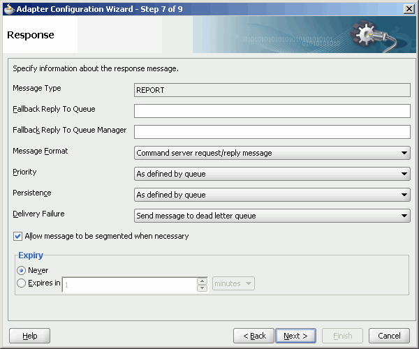
Description of "Figure 10-24 Response Page (Normal Message Type Selected)"
You can specify the following properties in the Response page:
-
(Optional) Fallback Reply to Queue: Enter a response fallback queue name. The response message is enqueued to the queue specified with the replyToQueue property of the request message. However, if the replyToQueue property is not set on the request message, then entering a name here ensures that the process does not fail to enqueue the response.
-
(Optional) Fallback Reply to Queue Manager: Enter a secondary queue name. This name is used when the primary queue manager that was established when you specified the JNDI connection name cannot access the queue name entered in the Queue Name field. This is similar to the functionality described in the Fallback Reply to Queue field.
To specify the other properties in this Response page, see properties mentioned for Figure 10-23.
When you click Next in the Response page, the Messages page shown in Figure 10-25 is displayed. You can perform the following tasks in this page:
-
Specify if native format translation is not required.
-
Select the XSD schema file for translation.
-
Start the Native Format Builder wizard to create an XSD file from file formats such as CSV, fixed-length, DTD, and COBOL Copybook.
For more information about the Messages page, see Enqueue Message.
In asynchronous request-reply interaction, you must map the following properties from the inbound message header to the outbound message header:
-
MsgID: Refers to the message ID. -
CorrelID: Refers to the correlation ID of a message. -
CorrelationScheme: Refers to a combination of both the msgid and the correlid of the request message.For more information, see Correlation Schemas.
-
ReplyToQ: Refers to the name of the response queue name. -
ReplyToQueueManager: Refers to the name of the response queue manager.
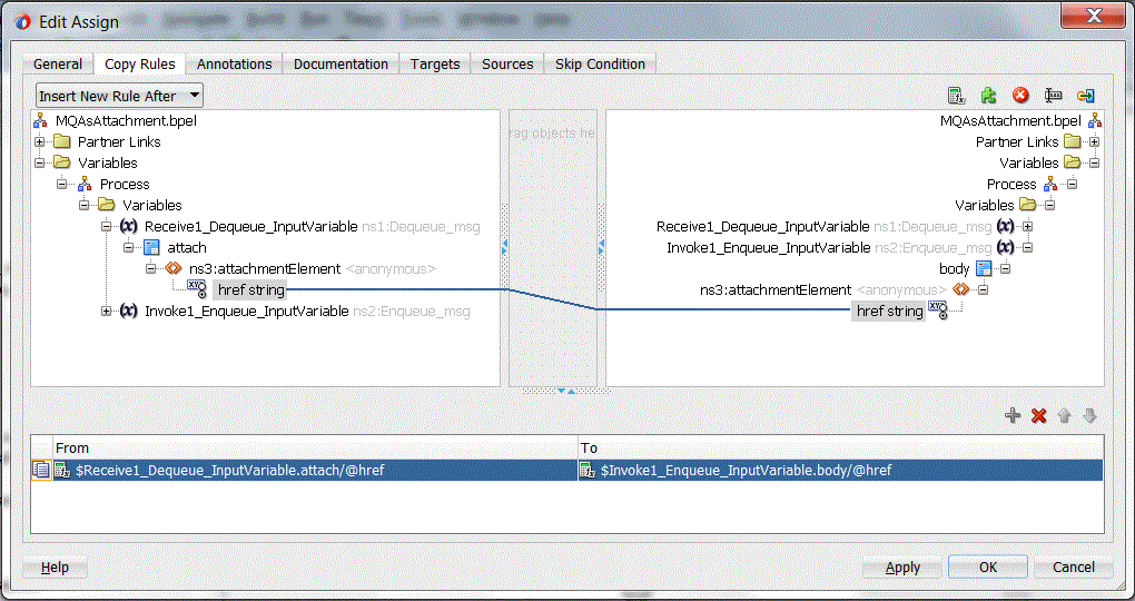
You can use the Assign activity to map these properties.
-
Create a BPEL process and double-click to open the BPEL Designer page.
-
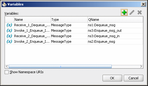
In the vertical menu that appears, click the Variables icon that appears as (x) grayed out. The Variables dialog is displayed, as shown in Figure 10-26.
-
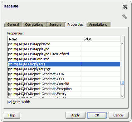
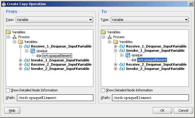
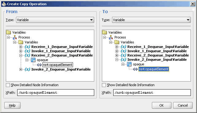
Capture the inbound header messages into these variables, as shown in Figure 10-27 and Figure 10-28.
-
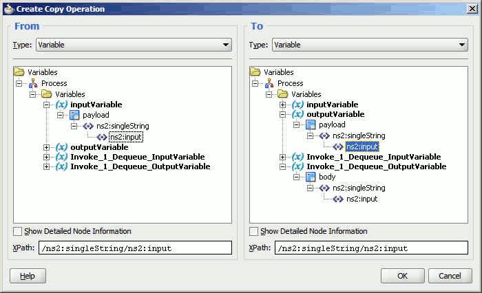
Assign the variables captured in Step 2 for the Outbound Reply message, as shown in Figure 10-28 and Figure 10-23.
10.4.1.6 Synchronous Request-Response (Mediator As Server)
In this scenario, the Mediator receives a request, processes it, and sends the response synchronously. The Oracle MQ Series Adapter performs the following operations:
-
Dequeues the request message from the queue when the message arrives.
-
Reads and translates the message based on the translation logic defined at design time.
-
Publishes the message as an XML message to Mediator. The Mediator processes the request and sends the response to the Oracle MQ Series Adapter.
-
Receives the response message from the Mediator.
-
Formats the XML content as specified at design time.
-
Sets the properties of the message such as priority, expiry, message type, and persistence. These properties are based on the selections that you made in the Adapter Configuration Wizard.
-
Sends the message to the queue specified at design time in the Adapter Configuration Wizard.
Figure 10-19 displays the operation type that you must select in the Adapter Configuration Wizard.
From this page onwards, all the pages are similar to the pages explained in Synchronous Request-Response ( As Server).
Note:
The asynchronous request-response pattern is not supported for Mediator.
10.4.1.7 Synchronous Request-Response (Oracle BPEL PM As Client)
The Oracle MQ Series Adapter supports the outbound synchronous-solicit-request-response scenario. In this scenario, the adapter enqueues a normal/request message in a queue and expects the report/reply synchronously. The report/reply message arrives in the ReplyToQueueName queue of the normal/request message.
Note:
Outbound synchronous-solicit-responses must be executed in non-XA modes as the request message does not get enqueued when it is participating in a global transaction.
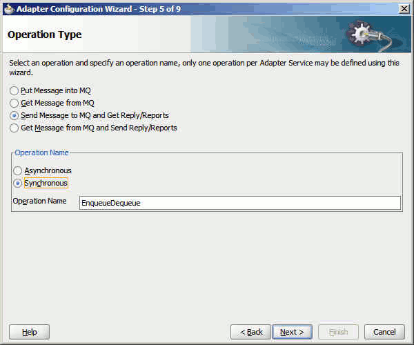
Figure 10-29 displays the operation type that you must select in the Adapter Configuration Wizard.
The page that appears after selecting the Send Message to MQ and Get Reply/Reports operation type is shown in Figure 10-13.
You can specify the following properties in this page:
-
Message Type: The type of the message. You can either send a normal message or a request message.
-
Queue Name: The name of the queue to which the Oracle MQ Series Adapter enqueues the message. This is a mandatory field.
-
Queue Manager: The name of the queue manager to which the queue belongs. This field is optional and is necessary when enqueuing message to a remote queue.
-
Message Format: The format of the message.
-
Priority: The priority of the message ranging from 0 (low) to 9 (high).
-
Persistence: The persistence of the message. You can also specify the persistence of the message to be taken from the default persistence attribute, as defined by the destination queue.
-
Delivery Failure: If delivery of the message fails, then either it can be put to a dead letter queue or it can be discarded.
-
Allow Messages to Be Segmented When Necessary: This is applicable to a message that is big enough for the queue to accommodate. In that case, if you have specified that it has to be segmented, then the single message can be broken into that many bytes the queue can take, which results in multiple messages.
-
Expiry: The expiry time of the message. The message is discarded after the expiry time has elapsed.
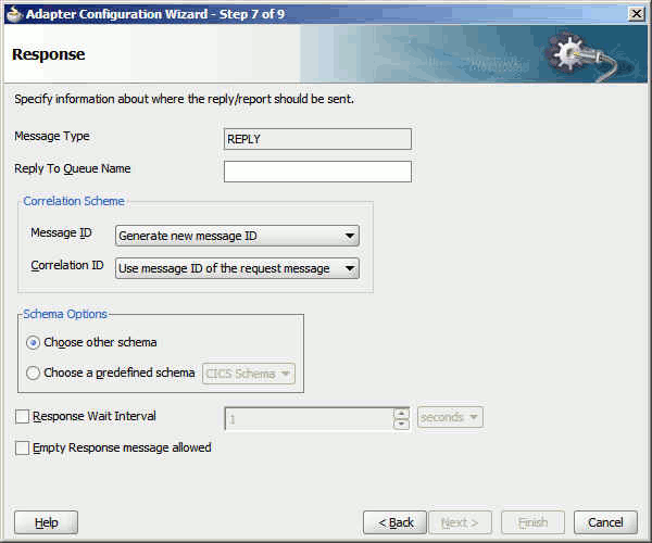
Click Next in the Send Message to MQ and Get Reply/Reports page, the Response page, as shown in Figure 10-30, is displayed.
For the Synchronous Request-Response scenario, you must also edit the following properties in the Response page:
-
Reply to Queue Name: The name of reply queue name.
-
Correlation Scheme: The correlation schema that must be used by the Oracle MQ Series Adapter.
For more information about correlation schemas, see Correlation Schemas.
-
Schema Options: This option enables you to specify the schema for the message to be dequeued.
-
Choose Other Schema: This option enables you to choose your schema for the message to be dequeued.
-
Choose a Predefined Schema: This option enables you to choose a readymade schema that the adapter provides.
-
-
Response Wait Interval: The permitted value for this property is any interval value (>= 0). This is the time in milliseconds during which the adapter waits for the report/reply to arrive in
replyToQueueName. By default, the value of this property is 0 milliseconds. You can change this value, but the value must be less than that of the timeout interval for the outbound activity. If the report/reply message does not arrive in the stipulated time, then the adapter throws an exception. This property is not mandatory.
Note:
The ResponseWaitInterval value must be less than the timeout interval for the outbound activity. If the ResponseWaitInterval value exceeds the outbound activity timeout, then the adapter can behave ambiguously.
10.4.1.8 Synchronous Request-Response (Oracle Mediator as Client)
The Oracle MQ Series Adapter also supports the outbound synchronous-solicit-request-response scenario. In this scenario, the adapter enqueues a normal/request message in a queue and expects the report/reply synchronously. The report/reply message arrives in the Reply to Queue Name queue of the normal/request message.
The Synchronous Request-Response scenario for Oracle Mediator as client is same as the Synchronous Request-Response for Oracle BPEL as client. For more information about the Synchronous Request-Response scenario, see Synchronous Request-Response ( As Client).
10.4.1.9 Asynchronous Request-Response (Oracle Mediator As Client)
In this scenario, Oracle Mediator sends a request message and receives the corresponding response from the Mediator callback handler. Oracle Mediator sends an outbound invocation to send the request. The Oracle MQ Series Adapter performs the following operations:
-
Receives message from Oracle Mediator.
-
Formats the XML content as specified at design time in the Adapter Configuration Wizard.
-
Sets properties and a correlation schema on the request message.
-
Sends the message to the queue specified at design time. The third-party application receives the message, processes it, generates the response, and then enqueues the response message to the
replyToqueue specified in the request message. The Correlation ID and Message ID of the response message is generated based on the correlation schema specified in the request message. -
The Oracle MQ Series Adapter dequeues the message from the
replyToqueue. -
Sets the properties of the message such as priority, expiry, message type, and persistence. These properties are based on the selections that you made in the Adapter Configuration Wizard.
-
Sends the response to the non-initiating receive activity of the BPEL process. To ensure that response is sent to the correct BPEL instance, correlation schemas are used.
Figure 10-12 displays the operation type that you must select in the Adapter Configuration Wizard.
The page that appears after selecting the Send Message to MQ and Get Reply/Reports operation type is shown in Figure 10-13.
You can specify the following properties in this page:
-
Message Type: The type of the message. You can either send a normal message or a request message.
-
Queue Name: The name of the queue to which the Oracle MQ Series Adapter enqueues the message. This is a mandatory field.
-
Message Format: The format of the message.
-
Queue Manager: The name of the queue manager to which the queue belongs. This field is optional and is necessary when enqueuing message to a remote queue.
-
Priority: The priority of the message ranging from 0 (low) to 9 (high).
-
Persistence: The persistence of the message. You can also specify the persistence of the message to be taken from the default persistence attribute, as defined by the destination queue.
-
Delivery Failure: If delivery of the message fails, then either it can be put to a dead letter queue or it can be discarded.
-
Allow Messages to be Segmented When Necessary: This is applicable to a message that is big enough for the queue to accommodate. In that case, if you have specified that it has to be segmented, then the single message can be broken into that many bytes the queue can take, which results in mutliple messages.
-
Expiry: The expiry time of the message. The message is discarded after the expiry time has elapsed.
For more information about these properties, see Message Properties and Report Messages.
The page that is displayed when you click Next in the Send Message to MQ and Get Reply/Reports page can be a Reports page (shown in Figure 10-14) or a Response page (shown in Figure 10-15).
The Reports page shown in Figure 10-14 is displayed only if you have selected the Get Reports option in the Send Message to MQ and Get Reply/Reports page shown in Figure 10-13.
The Response page shown in Figure 10-15 is displayed, irrespective of whether you select the Request or Normal option. The only difference is that if you select the Request option, then REPLY is displayed in the Message Type field of the Response page. On the other hand, if you select the Normal option, then REPORTS is displayed in the Message Type field of the Response page.
You can select the following types of reports in Figure 10-14:
-
Confirmation on Arrival
-
Confirmation on Delivery
-
Exception Report
-
Expiry Report
For information about these report types, see Report Messages.
The Response page, shown in Figure 10-15, is displayed when you click Next in the Reports page.
You can specify the following properties in the Response page:
-
Reply to Queue Name: The name of reply queue name.
-
Correlation Scheme: The correlation schema that is used by the Oracle MQ Series Adapter.
For information about correlation schemas, see Correlation Schemas.
-
Schema Options: This option enables you to specify the schema for the message to be dequeued.
-
Choose Other Schema: This option enables you to choose your schema for the message to be dequeued.
-
Choose a Predefined Schema: This option enables you to choose a readymade schema that the adapter provides.
-
Note:
For Oracle MQ Series Adapter in an asynchronous outbound request/reply scenario, properties are differentiated by an (Enqueue) or (Dequeue) label in Oracle Enterprise Manager Console. For example, QueueName(Enqueue) is used for putting a message and QueueName(Dequeue) is used for dequeuing the reply.
When using Oracle Enterprise Manager Console to edit Oracle MQ Series Adapter properties in this scenario, note the following:
-
If you change the
ReplyToQueueName(Enqueue)property, you must also change theQueueName(Dequeue)property to the same value. -
If you change the
MessageId(Dequeue)property, you must also change theMessageId(Enqueue)property to the same value. -
If you change the
CorrelationId(Dequeue)property, you must also change theCorrelationId(Enqueue)property to the same value.
When you click Next in the Response page, a Messages page shown in Figure 10-16 is displayed. This page enables you to select the XSD schema file for translation for request and as response message.
For more information about the Messages page, see Enqueue Message.
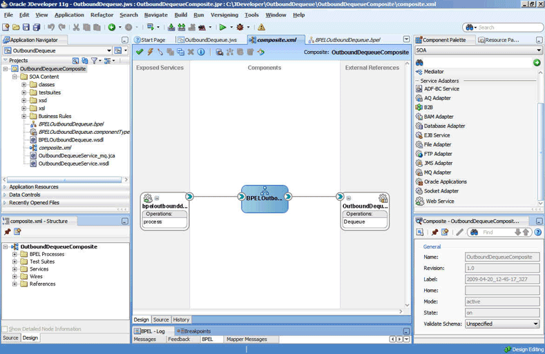
10.4.1.10 Outbound Dequeue Scenario
The outbound dequeue scenario dequeues a single message from a queue using the outbound Oracle MQ Series Adapter by using the Get Message from MQ option in the Operation Type page of the Adapter Configuration Wizard. To enable the outbound dequeue option, you must select the Synchronous option, as shown in Figure 10-29.
Click Next in the Send Message to MQ and Get Reply/Reports page, the Response page, as shown in Figure 10-30, is displayed. You must set the following properties in the Response page:
-
QueueName: This is the name of the MQ Series queue from which the message is dequeued. This property is mandatory.
-
Response Wait Interval: This is the time (in milliseconds) that the adapter waits if the message is not in the queue. The default value for this property is 0 milliseconds. This property is not mandatory. The permitted value for this property is any integer value (>=0). The value of this property must be less than that of the timeout for outbound activity.
Note:
The
ResponseWaitIntervalvalue must be less than the timeout interval for the outbound activity. If theResponseWaitIntervalvalue exceeds the outbound activity timeout, then the adapter can behave ambiguously.
Optionally, the following two header properties can be used to filter the dequeued message based on Message Id and Correlation Id.:
-
jca.mq.MQMD.MsgId: This property sets the message filter option based on themessageId. The value provided for this property must be a hexadecimal-encoded value for somemessageId. -
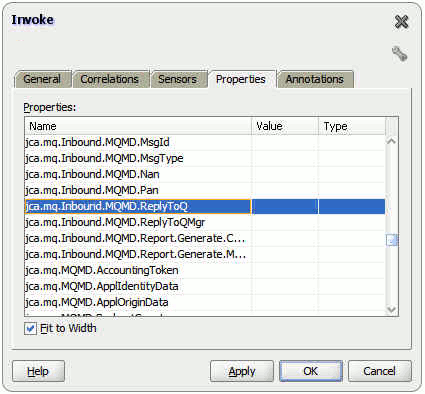
jca.mq.MQMD.CorrelId: This property sets the message filter option based on thecorrelationId. The value provided for this property must be a hexadecimal-encoded value for somecorrelationId.
10.4.2 Message Properties
The Oracle MQ Series Adapter supports the following message properties:
10.4.2.1 Messages Types
The Oracle MQ Series Adapter supports the following four types of messages:
-
Normal Message
A normal message is sent by one program to another program without expecting any response.
-
Request Message
A request message is sent by one program to another program requesting a response.
-
Reply Message
A reply message is sent by a program in response to a request message.
-
Report Message
A report message is sent by a receiving program to a sending program as confirmation of successful or unsuccessful delivery of a message. A report message can be generated for any of the message types, normal message, request message, or reply message.
For more information about acknowledgment messages supported by the Oracle MQ Series Adapter, see Report Messages.
10.4.2.2 Message Format
You can specify the format for an outgoing message through the Adapter Configuration Wizard, as shown in Figure 10-8. The following message formats are supported:
-
No format name (Default)
-
Command server request/reply message
-
Type 1 command reply message
-
Type 2 command reply message
-
Dead letter header
-
Event message
-
User-defined message in programmable command format
-
Message consisting entirely of characters
-
Trigger message
-
Transmission queue header
10.4.2.3 Message Expiry
You can specify the expiry time for an outgoing message by using the Adapter Configuration Wizard, as shown in Figure 10-8. The queue manager discards the message after the expiry time of a message has elapsed.
If a message has expiration notification set, then a notification is generated when the message is discarded. The notification is sent to the queue specified in the replyToQueue parameter. By default, NEVER is set for the expiry field.
10.4.2.4 Message Priority
You can specify the priority of an outgoing message through the Adapter Configuration Wizard, as shown in Figure 10-8. A priority can be in the range of 0 (low) to 9 (high). You can also specify the priority of the message to be taken from the default priority attribute, as defined by the destination queue. By default, AS_Q_DEF is set as message priority.
10.4.2.5 Message Persistence
You can specify the persistence of an outgoing message through the Adapter Configuration Wizard, as shown in Figure 10-8. If message persistence is not set, then a message is lost when the queue manager restarts or there is a system failure. If you set persistence for a message to true, then it means that the message does not get lost even if there is system failure or the queue manager is restarted. You can also specify the persistence of the message to be taken from the default priority attribute, as defined by the destination queue. The Adapter writes persistent messages to log files and queue data files. If a queue manager is restarted after a failure, it recovers these persistent messages from these files.
Note:
You can specify all these message properties at run time through message headers. You can use the assign activity to assign values to these properties.
10.4.3 Correlation Schemas
Mapping a response to a request in a request-reply interaction requires correlation. Each MQ Series request message contains a message ID and a correlation ID. When an application receives a request message from Oracle BPEL PM, it checks for the correlation schema defined for the response message. Based on the correlation schema, the application generates the message ID and correlation ID of the response message.
The response page of the Adapter Configuration Wizard shown in Figure 10-15 enables you to specify the correlation schema for the response message.
The Message ID box shown in Figure 10-15 provides the following options for the message ID of the response message:
-
Generate a new message ID for the response message.
-
Use the message ID of the request message.
Similarly, the Correlation ID box shown in Figure 10-15 provides the following options for the correlation ID of the response message:
-
Use the message ID of the request message
-
Use the correlation ID of the request message
10.4.4 Distribution List Support
The Oracle MQ Series Adapter enables you to enqueue a message to multiple queues.
When you select the Put Message Into MQ option in the Operation Type page and multiple queues, then the DistributionList parameter is automatically added to the JCA file.
10.4.5 Report Messages
The Oracle MQ Series Adapter enables you to set various types of acknowledgment messages on an outgoing message. These acknowledgment messages are known as report messages. A report message is generated, only if the criteria for generating that report message is met. When enqueuing a message on a queue, you can request for more than one type of report message. When you request for a report message, you must specify the queue name to which the report message is sent. This queue is known as replyTo queue. A report message can be generated by a queue manager, a message channel, or an application.
The Oracle MQ Series Adapter supports the following message reports:
-
Confirmation on Arrival
The Confirmation on Arrival (COA) message indicates that the message has been delivered to the target queue manager. A COA message is generated by the queue manager. This message report can be selected in the Reports page of the Adapter Configuration page shown in Figure 10-14.
-
Confirmation on Delivery
A Confirmation on Delivery (COD) message indicates that the message has been retrieved by the receiving application. A COD message is generated by the queue manager. This message report can be selected in the Reports page shown in Figure 10-14.
-
Exception Report
An exception report is generated when a message cannot be delivered to the specified destination queue. Exception reports are generated by the message channel. This message report can be selected in the Reports page of the Adapter Configuration page shown in Figure 10-14.
-
Expiry Report
An expiry report indicates that the message was discarded because the expiry time specified for the message elapsed before the message was retrieved. An expiry report is generated by a queue manager. This message report can be selected in the Reports page of the Adapter Configuration page shown in Figure 10-14.
-
Positive Action Notification
A Positive Action Notification (PAN) indicates that a request has been successfully processed. It means that the action requested in the message has been performed successfully. This type of report is generated by the application.
-
Negative Action Notification
A Negative Action Notification (NAN) indicates that a request has not been successfully serviced. It means that the action requested in the message has not been performed successfully. This type of report is generated by the application.
You can specify whether all these report messages except PAN and NAN should contain the complete original message, a part of the original message, or no part of the original message. You can select any of the following options in the Adapter Configuration Wizard:
-
No data from the original message
-
The first 100 bytes of data in the original message
-
The entire original message
10.4.6 Message Delivery Failure Options
The Message Delivery Failure options are supported only for remote queues and not for normal queues. The Oracle MQ Series Adapter enables you to specify the action that should be taken in case a message could not be delivered to the destination queue. You can specify any of:
-
Place message on a dead letter queue
This is the default action. A message is placed on a dead-letter queue if it cannot be delivered to the destination queue. A report message is generated if requested by the sender.
-
Discard message
This indicates that the message should be discarded if it cannot be delivered to the destination queue. A report message is generated if requested by the sender.
You can specify these options by selecting the Put Message To MQ option in the Adapter Configuration Wizard.
10.4.7 Message Segmentation
The Oracle MQ Series Adapter supports message segmentation for both inbound and outbound interactions. Segmentation is required when the size of a message is greater than the message size allowed for a queue. A physical message is divided into two or more logical messages. All logical messages have the same group ID and a sequence number, and an offset.
In the inbound interaction, the segmentation is inherently supported by the Oracle MQ Series Adapter. The Oracle MQ Series Adapter dequeues all logical messages in the order of sequence number and then publishes the single message as XML to Oracle BPEL PM or Mediator.
The Allow Messages to Be Segmented When Necessary option enables you to segment messages for outbound interactions. This option appears in the Response page of the Adapter Configuration Wizard.
The message is segmented based on whether the size of the message is larger than the maximum limit set on the queue.
Message Segmentation is not supported when using Distribution Lists. This is due to a limitation in the Java API of the IBM MQ series product that is used by the MQ Adapter.
10.4.8 Integration with CICS
The Oracle MQ Series Adapter provides support for sending and receiving messages from the CICS server. In the inbound direction, an inbound message from the CICS server is dequeued in the same way as a normal message. In the outbound direction, the message should be in the CICS format. A sample schema file for the outbound CICS message format is shown in the following XSD example. You should also refer to the list of supported Oracle MQ Series Adapter encodings in Oracle MQ Series Adapter Encodings.
<?xml version="1.0" ?><schema xmlns="http://www.w3.org/2001/XMLSchema"
        targetNamespace="http://xmlns.oracle.com/pcbpel/nxsd/cics_mqcih"
        elementFormDefault="qualified"
        attributeFormDefault="unqualified"

        xmlns:nxsd="http://xmlns.oracle.com/pcbpel/nxsd"
        nxsd:version="NXSD"

        nxsd:encoding="UTF8"
        nxsd:stream="bytes"
        nxsd:byteOrder="bigEndian"

        xmlns:nxsd_extn="http://xmlns.oracle.com/pcbpel/nxsd/extensions"

<element name="MSGForMQCICSBridge">
    <complexType>
      <sequence>
        <element name="MQCIH">
          <complexType>
            <sequence>
              <!--
              MQCHAR4   StrucId;
              Structure identifier
              -->
              <element name="StrucId" type="string"
               nxsd:style="fixedLength" nxsd:length="4" nxsd:padStyle="tail"/>

              <!--
              MQLONG    Version;
              Structure version number 1 or 2
              -->
              <element name="Version" type="string"
               nxsd:style="integer" nxsd_extn:octet="4"
               nxsd_extn:align="0" nxsd_extn:sign="unticked" />
              <!--
              MQLONG    StrucLength;
              Length of MQCIH structure V1=164 V2=180
              -->
              <element name="StrucLength" type="string"
               nxsd:style="integer" nxsd_extn:octet="4"
               nxsd_extn:align="0" nxsd_extn:sign="unticked" />

              <!--
              MQLONG    Encoding;
              Reserved
              -->
              <element name="Encoding" type="string"
               nxsd:style="integer" nxsd_extn:octet="4"
               nxsd_extn:align="0" nxsd_extn:sign="unticked" />

              <!--
              MQLONG    CodedCharSetId;
              Reserved              -->
              <element name="CodedCharSetId" type="string"
               nxsd:style="integer" nxsd_extn:octet="4" nxsd_extn:align="0"
               nxsd_extn:sign="unticked" />

              <!--
              MQCHAR8   Format;
              MQ Format name
              -->
              <element name="Format" type="string"
              nxsd:style="fixedLength" nxsd:length="8" />

              <!--
              MQLONG    Flags;
              Reserved
              -->
              <element name="Flags" type="string"
               nxsd:style="integer" nxsd_extn:octet="4" nxsd_extn:align="0"

               nxsd_extn:sign="unticked" />

              <!--
              MQLONG   ReturnCode;
              Return code from bridge
              -->
              <element name="ReturnCode" type="string"
               nxsd:style="integer" nxsd_extn:octet="4" nxsd_extn:align="0"
               nxsd_extn:sign="unticked" />

              <!--
              MQLONG   CompCode;
              MQ completion code or CICS EIBRESP
              -->
              <element name="CompCode" type="string"
               nxsd:style="integer" nxsd_extn:octet="4" nxsd_extn:align="0"
               nxsd_extn:sign="unticked" />

              <!--
              MQLONG   Reason;
              MQ reason or feedback code, or CICS EIBRESP2
              -->
              <element name="Reason" type="string"
               nxsd:style="integer" nxsd_extn:octet="4" nxsd_extn:align="0"
               nxsd_extn:sign="unticked" />

              <!--
              MQLONG   UOWControl;
              Unit-of-work control
              -->
              <element name="UOWControl" type="string"
               nxsd:style="integer" nxsd_extn:octet="4" nxsd_extn:align="0"
               nxsd_extn:sign="unticked" />

              <!--
              MQLONG   GetWaitInterval;
              Wait interval for MQGET call issued by bridge
              -->
              <element name="GetWaitInterval" type="string"
               nxsd:style="integer" nxsd_extn:octet="4" nxsd_extn:align="0"
               nxsd_extn:sign="ticked" />

              <!--
              MQLONG   LinkType;
              Link type
              -->
              <element name="LinkType" type="string"
               nxsd:style="integer" nxsd_extn:octet="4" nxsd_extn:align="0"
              nxsd_extn:sign="unticked" />

              <!--
              MQLONG   OutputDataLength;
              Output commarea data length
              -->
              <element name="OutputDataLength" type="string"
               nxsd:style="integer" nxsd_extn:octet="4" nxsd_extn:align="0"
               nxsd_extn:sign="ticked" />

              <!--
              MQLONG   FacilityKeepTime;
              Bridge facility release time
              -->
              <element name="FacilityKeepTime" type="string"
               nxsd:style="integer" nxsd_extn:octet="4" nxsd_extn:align="0"
               nxsd_extn:sign="unticked" />

              <!--
              MQLONG   ADSDescriptor;
              Send/receive ADS descriptor
              -->
              <element name="ADSDescriptor" type="string"
               nxsd:style="integer" nxsd_extn:octet="4" nxsd_extn:align="0"
               nxsd_extn:sign="unticked" />

              <!--
              MQLONG   ConversationalTask;
              Whether task can be conversational
              -->
              <element name="ConversationalTask" type="string"
               nxsd:style="integer" nxsd_extn:octet="4" nxsd_extn:align="0"
               nxsd_extn:sign="unticked" />
                            <!--
              MQLONG   TaskEndStatus;
              Status at end of task
              -->
              <element name="TaskEndStatus" type="string"
               nxsd:style="integer" nxsd_extn:octet="4" nxsd_extn:align="0"
               nxsd_extn:sign="unticked" />


              <!--
              MQBYTE   Facility[8];
              BVT token value. Initialise as required.
              -->
              <element name="Facility" type="string"
               nxsd:style="integer" nxsd_extn:octet="8" nxsd_extn:align="0"
               nxsd _extn:sign="unticked" />

              <!--
              MQCHAR4  Function;
              MQ call name or CICS EIBFN function name
              -->
              <element name="Function" type="string"
               nxsd:style="fixedLength" nxsd:length="4" />

              <!--
              MQCHAR4  AbendCode;
              Abend code
              -->
              <element name="AbendCode" type="string"
               nxsd:style="fixedLength" nxsd:length="4" />

              <!--
              MQCHAR8  Authenticator;
              Password or passticket
              -->
              <element name="Authenticator" type="string"
              nxsd:style="fixedLength" nxsd:length="8" />

              <!--
              MQCHAR8  Reserved1;
              Reserved
              -->
              <element name="Reserved1" type="string"
               nxsd:style="fixedLength" nxsd:length="8" />

              <!--
              MQCHAR8  ReplyToFormat;
              MQ format name of reply message
              -->
              <element name="ReplyToFormat" type="string"
               nxsd:style="fixedLength" nxsd:length="8" />

              <!--
              MQCHAR4  RemoteSysId;
              Remote sysid to use
              -->
              <element name="RemoteSysId" type="string"
              nxsd:style="fixedLength" nxsd:length="4" />

              <!--
              MQCHAR4  RemoteTransId;
              Remote transid to attach
              -->
              <element name="RemoteTransId" type="string"
               nxsd:style="fixedLength" nxsd:length="4" />

              <!--
              MQCHAR4  TransactionId;
              Transaction to attach
              -->
              <element name="TransactionId" type="string"
               nxsd:style="fixedLength" nxsd:length="4" />

              <!--
              MQCHAR4  FacilityLike;
              Terminal emulated attributes
              -->
              <element name="FacilityLike" type="string"
               nxsd:style="fixedLength" nxsd:length="4" />

              <!--
              MQCHAR4  AttentionId;
              AID key
              -->
              <element name="AttentionId" type="string"
               nxsd:style="fixedLength" nxsd:length="4" />

              <!--
              MQCHAR4  StartCode;
              Transaction start code
              -->
              <element name="StartCode" type="string"
              nxsd:style="fixedLength" nxsd:length="4" />

              <!--
              MQCHAR4  CancelCode;
              Abend transaction code
              -->
              <element name="CancelCode" type="string"
               nxsd:style="fixedLength" nxsd:length="4" />

              <!--
              MQCHAR4  NextTransactionId;
              Next transaction to attach
              -->
              <element name="NextTransactionId" type="string"
              nxsd:style="fixedLength" nxsd:length="4" />

              <!--
              MQCHAR8  Reserved2;
              Reserved
              -->
              <element name="Reserved2" type="string"
              nxsd:style="fixedLength" nxsd:length="8" />
              <!--
              MQCHAR8  Reserved3;
              Reserved
              -->
              <element name="Reserved3" type="string"
              nxsd:style="fixedLength" nxsd:length="8" />

              <!--
              MQLONG   CursorPosition;
              Cursor position
              -->
              <element name="CursorPosition" type="string"
              nxsd:style="integer" nxsd_extn:octet="4" nxsd_extn:align="0"
              nxsd_extn:sign="unticked" />

              <!--
              MQLONG   ErrorOffset;
              Error offset
              -->
              <element name="ErrorOffset" type="string"
               nxsd:style="integer" nxsd_extn:octet="4" nxsd_extn:align="0"
               nxsd_extn:sign="unticked" />

              <!--
              MQLONG   InputItem;
              Input item
              -->
              <element name="InputItem" type="string"
               nxsd:style="integer" nxsd_extn:octet="4" nxsd_extn:align="0"
               nxsd_extn:sign="unticked" />

              <!--
              MQLONG   Reserved4;
              Reserved
              -->
              <element name="Reserved4" type="string"
              nxsd:style="integer" nxsd_extn:octet="4" nxsd_extn:align="0"
              nxsd_extn:sign="unticked" />
            </sequence>
          </complexType>
        </element>

        <!--
        Application data
        -->
        <element name="ApplicationData" type="string"
                                      fixed="Nothing" />

      </sequence>
    </complexType>
  </element>
</schema>
10.4.9 Using the MQ Series Client Channel Definition Table Feature
The CCDT provides several advantages when defining properties while configuring the JNDI for your MQ Series Adapter.
It is useful to understand how the Client Channel Definition Table works.
To understand the configuration of the Client Channel Definition Table, you should understand the following basic terms and concepts:
-
Channel name and Connection name: The channel name for each definition in the table should be exactly same as the server connection channel of the queue manager which has a listener running on the Connection name provided. For example, the first definition in the CCDT below,
channel.ccdt_qm1is the name of the server connection channel of a queue manager which has its listener running on localhost(1414). -
Queue manager name: The queue manager name defined in the CCDT might not be the actual name of the queue manager with Channel name and Connection name defined. There can be the following possibilities:
-
The Queue manager name defined in the client channel is the actual queue manager name as in the third definition in the table. Hence,
ccdt_qm3is the actual name of the queue manager which has thechannel.ccdt_qm3as its server connection channel and has a listener listening on localhost(3414). -
No Queue manager name is defined for a client channel definition. In Figure 10-31, this situation can be seen for the fourth definition in the table which does not have a Queue manager name defined.
-
Two or more client channel entries in the CCDT have the same Queue manager name defined. This name can match with the actual queue manager name of any of the entries. The first and second definition in Figure 10-31 have the same Queue manager name defined as
QMthough they actually point to different queue managers.Figure 10-31shows a standard CCDT which has client channels defined for connections to four queue managers; that is,
ccdt_qm1toccdt_qm4.Once defined, this CCDT resides, by default, at the following locations:
-
For Windows,
<C:\Program Files\IBM\ MQ\qmgrs\QM_NAME\@ipcc\AMQCLCHL.TAB> -
For Unix-based systems,
<var/mqm/qmgrs/QM_NAME/@ipcc/AMQCLCHL.TAB>
-
-
This feature simplifies what was formerly a task that involved defining the Hostname, PortNumber, ChannelName and QueueManagerName in ConnectionFactory properties while you were configuring the JNDI for your MQ Series Adapter.
-
You can use the Client Channel Definition Table feature (CCDT), with only the URL pointing to a CCDT file and, additionally, a QueueManagerName, as part of the configuration. The MQ Series Adapter is able to read the rest of the connection details from the CCDT to create the required connections for your MQ Series Adapter.
-
You can configure the MQ Series Adapter to dynamically connect to the available queue manager from a list of queue managers, a few of which might be down.
-
You do not have to change the JNDI used for the MQ Adapter in the composite process and then re-deploy the composite to change the queue manager on which the MQ adapter was required to connect.
-
Only one ConnectionFactory JNDI entry is required for the queue managers and the MQ adapter will dynamically connect to the first available queue manager.
-
CCDT can be used to define a list of queue managers with the same Queue Manager name property for the client channel definition. This list is used by the MQ Series Adapter to dynamically connect to the first available Queue Manager at runtime without requiring any configuration changes or redeployment.
You can gain a basic understanding of IBM MQ and MQ adapter usage and details about CCDT creation in the IBM MQ Series documentation.
IBM MQ version 6 is the minimum requirement for the CCDT feature to work.
10.4.10 Large Payload Support
MQ Adapter now supports reading and writing large payloads as MQ messages. See the following sections for information about configuring the inbound and the outbound MQ Series Adapter for large payloads.
10.4.10.1 Configuring the Inbound MQ Adapter for Large Payloads
For inbound processing, you can configure the inbound MQ Adapter for large payloads by the selecting the Use Large Message Support checkbox while configuring the inbound adapter through the MQ Series Adapter Configuration Wizard. The following screenshot shows this.
Figure 10-32 Configuring Large Message Support at inbound in MQ Series Adapter
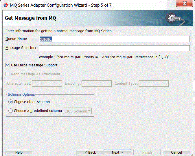
Description of "Figure 10-32 Configuring Large Message Support at inbound in MQ Series Adapter"
10.4.10.2 Configuring the Outbound MQ Adapter for Large Payloads
At outbound, there is no required configuration for large payload support. But two optional configurations are important for outbound processing:
1. SegmentIfRequired property: By default, this property is set to TRUE; you can configure this by using the Allow message to segmented when necessary checkbox while configuring the outbound MQ adapter. You must set this boolean property to true if you want the MQ Adapter to break large messages into smaller segments. If this property is set to false, and the size of the message exceeds the maximum message size allowed by the queue, channel or queue manager, the MQ server does not permit putting the message into the queue and the MQ Adapter throws an exception.
2. MaximumSegmentLength: By default set to Maximum Allowed, you can configure this property by using the Maximum Segment Length, radio buttons while configuring the outbound MQ adapter through the wizard. By selecting the Custom, radio button, you can configure a user-defined message segment length and the adapter segments the message in that size. When Maximum Allowed radio button is selected, the MQ Adapter segments the messages into the maximum segment size that the outbound queue, channel and queue manager allow.
Note that if the custom segment value provided is higher than that allowed on the MQ server, then the value specified by the server will be honored.
The following figure shows the two configurations.
Figure 10-33 Configuring Large Message Support at Outbound in MQ Series Adapter
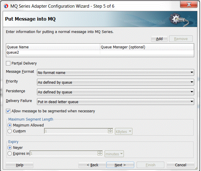
Description of "Figure 10-33 Configuring Large Message Support at Outbound in MQ Series Adapter"
10.4.11 Attachment Support
The MQ Adapter supports processing messages as attachment. When processing inbound messages as attachment, the MQ Adapter ignores translating the payload and directly transfers the message to the next component. Similarly, at outbound, when writing as an attachment, the MQ Adapter ignores translating the payload and opaquely writes the message to the queue. This feature is useful when opaquely transferring large messages for one queue to another.
You can configure the MQ Adapter to process a message as an attachment by selecting the Read Message As Attachment checkbox while configuring the inbound adapter using the configuration wizard. More details can be found in the use case section 10.6.9.
Figure 10-34 Configuring Inbound MQ Adapter to Read Message as Attachment
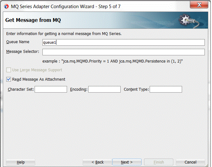
Description of "Figure 10-34 Configuring Inbound MQ Adapter to Read Message as Attachment"
10.5 Configuring the Oracle MQ Series Adapter
The prerequisites for using the Oracle MQ Series Adapter are:
-
IBM MQ server should be installed and running.
-
A queue manager and a server connection channel should be created.
Note:
You must create queues based on the requirement of the application.
To configure the Oracle MQ Series Adapter, perform the following:
10.5.1 Adding jar Files to the Oracle MQ Series Adapter Classpath: MQ Series 6 and 7
The steps in this section should be performed once, before using the Oracle MQ Series Adapter.
To add correct jar properties to the classpath for the Oracle MQ Series 6 Adapter, copy the following jar to <DOMAIN_HOME>/lib folder
-
com.ibm.mq.jar
To add correct jar properties to the classpath for the Oracle MQ Series 7 Adapter, copy the following jars to <DOMAIN_HOME>/lib folder
-
com.ibm.mq.commonservices.jar -
com.ibm.mq.jar -
com.ibm.mq.pcf.jar -
com.ibm.mq.headers.jar -
com.ibm.mq.jmqi.jar -
com.ibm.mqetclient.jar(for use with XA. Note that for any version prior to 7.5, you must have thiscom.ibm.mqetclient.jarfor XA Transaction Scenarios. The jar is not provided with normal installation of IBM MQ Series. To procure this JAR, you must obtain extra licenses from IBM.)
In addition, if you are using the Oracle MQ Series 7 Adapter , the new Sharing Conversation property of the Server Connection Channel has to be to set to zero.
For version 7.5 of IBM MQ Series, you must have the following jars:
-
com.ibm.mq.jar
-
com.ibm.mq.jmqi.jar
-
com.ibm.mqjms.jar
-
dhbcore.jar
The com.ibm.mqetclient.jar is not required with the MQ Series 7.5 server. Running XA transactions will work without the presence of that jar if you are using MQ Series 7.5.
10.5.2 Adding JNDI Entry
You can add a new JNDI entry in the Oracle WebLogic Server Administration Console by following these steps:
10.5.3 Enabling Binding Mode for Connections
You can enable binding mode for connections for the Oracle MQ Series Adapter by modifying a few properties in the Oracle WebLogic Server Administration Console:
To enable binding mode, perform the following steps:
You have enabled the binding mode for connections for the Oracle MQ Series Adapter.
10.5.4 Selective Dequeue of Messages Using Message Selectors
When two or more BPEL processes receive messages from the same queue, the messages are not assured of delivery to the correct BPEL process and can be associated with any of the BPEL processes listening on the queue.
However, you can set up processes so only one process listens for messages from any particular queue.
To accomplish this, you can configure the MQ adapter to dequeue only those messages that satisfy the message selection criteria and discard those which do not.
These messages can then be received by any other BPEL process listening for messages from the same queue, if the message satisfies its selection criteria.
Before examining the syntax and rules associated with the Message Selector, it is useful to look at the Message Selector in the context of the MQ Adapter Configuration Wizard.
Note that the message selectors of the all the BPEL processes receiving messages from the same queue must be exclusive of each other.
10.5.4.1 Message Selector in the MQ Adapter Configuration Wizard
The Message Selector feature appears on the Get Messages from MQ Screen in the MQ Adapter Wizard. When you specify a Message Selector, the Wizard places the selector information you specify in the activation-spec. As you can see in Figure 10-42, the Message Selector field is directly below the Queue Name field.
Figure 10-42 Message Selector Field on the Get Message from MQ Screen in the MQ Adapter Configuration Wizard
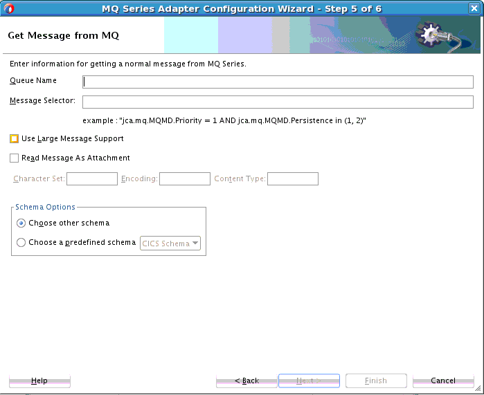
Description of "Figure 10-42 Message Selector Field on the Get Message from MQ Screen in the MQ Adapter Configuration Wizard"
10.5.4.2 Using Message Selectors with MQ
A message selector enables you to specify which messages the selector is interested in to dequeue from the MQ queue. Only those messages whose headers and properties match the selector are dequeued.
A message satisfies the selector if the selector evaluates to true when the message's header fields and property values are substituted for their corresponding identifiers in the selector.
A message selector is defined as an activation spec property when you use the MQ Configuration Wizard Adapter to configure the inbound MQ Adapter. A sample message selector follows:
Example - Sample Message Selector for Inbound MQ Adapter
<property name="MessageSelector" value="((jca.mq.MQMD.Priority BETWEEN 0 AND 3) AND NOT(jca.mq.MQMD.Priority = 1)) AND jca.mq.MQMD.PutApplName LIKE 'WebSph_re MQ%' AND jca.mq.MQMD.MsgType NOT IN (0, 1) AND (jca.mq.MQMD.ReplyToQ = 'test_q2' OR jca.mq.MQMD.ReplyToQ IS NULL) AND name = 'Joe'"/>
If the MessageSelector is not defined, the MQ Adapter does not do any message selection and dequeues all the messages that arrive on the queue.
10.5.4.2.1 Message Selector Syntax: Literals
This section describes in detail the MessageSelector syntax. You must understand this syntax to fill in the selector information in the Selector box in the Get MQ Message screen that provides you the option to create a message selector.
The order of evaluation of the message selector is from left to right within the precedence level. Parenthesis can be used to change this order.
A selector can contain the following literals:
-
String: A string literal should be enclosed in single quotes. Like Java String literals, these would use the Unicode character encoding.
-
Exact Numeric: An exact numeric literal is a numeric value without a decimal point. Numbers in the range of Java Long will be supported.
-
Approximate Numeric: An approximate numeric literal is a number with a decimal point. All numbers in the range of Java double will be supported.
-
Boolean: True or False.
10.5.4.2.2 Message Selector Identifiers
Use the identifiers to identify the message header and the property values in the message selector. The message header properties are the MQMD properties and user defined properties and those defined in the USR folder of RFH2 header. Properties defined in other RFH2 folders are not supported for message selectors. Note that Identifiers
-
Are case-sensitive
-
Cannot be "AND", "OR", "NOT", "TRUE", "FALSE", "IN", "LIKE", "BETWEEN", "IS", "NULL", "ESCAPE" or "div".
-
Have a naming convention. Any identifier name that does not begin with 'jca.mq.MQMD.' will be considered as a USR folder property identifier of the RFH2 header.
In detail, the following constitute the identifiers.
-
MQMD header fields. See Table 10-5.
-
RFH2 USR Folder. Any property name defined in the USR folder of the RFH2 header of the MQ message can be used as an identifier. The property name can be an unlimited length character sequence that must begin with a Java Identifier start character and all the following characters must be Java Identifier part characters (which can include '.', '_' and '$').
Use of any other RFH2 Folder properties in message selector is not supported. Table 10-5 provides MQMD headers and Message Selector identifiers.
Table 10-5 MQMD Headers and Message Selector Identifiers
| MQMD header field | Identifier |
|---|---|
|
Accounting Token |
jca.mq.MQMD.AccountingToken |
|
Application Identity Data |
jca.mq.MQMD.ApplIdentityData |
|
Application Origin Data |
jca.mq.MQMD.ApplOriginData |
|
Backout Count |
jca.mq.MQMD.BackoutCount |
|
Coded Character Set Id |
jca.mq.MQMD.CodedCharSetId |
|
Correlation Id |
jca.mq.MQMD.CorrelId |
|
Encoding |
jca.mq.MQMD.Encoding |
|
Expiry |
jca.mq.MQMD.Expiry |
|
Feedback |
jca.mq.MQMD.Feedback |
|
Format |
jca.mq.MQMD.Format |
|
Group Id |
jca.mq.MQMD.GroupId |
|
Message Flags |
jca.mq.MQMD.MsgFlags |
|
Message Id |
jca.mq.MQMD.MsgId |
|
Message Sequence Number |
jca.mq.MQMD.MsgSeqNumber |
|
Message Type |
jca.mq.MQMD.MsgType |
|
Offset |
jca.mq.MQMD.Offset |
|
Original Length |
jca.mq.MQMD.OriginalLength |
|
Persistence |
jca.mq.MQMD.Persistence |
|
Priority |
jca.mq.MQMD.Priority |
|
Put Application Name |
jca.mq.MQMD.PutApplName |
|
Put Application Type |
jca.mq.MQMD.PutApplType |
|
Put Date Time |
jca.mq.MQMD.PutDateTime |
|
Reply to Queue Manager Name |
jca.mq.MQMD.ReplyToQMgr |
|
Reply to Queue Name |
jca.mq.MQMD.ReplyToQ |
|
Report |
jca.mq.MQMD.Report |
|
User Identifier |
jca.mq.MQMD.UserIdentifier |
10.5.4.2.3 Message Selector Expressions
Expressions within message selectors are of these types:
-
Arithmetic: Composed of themselves, arithmetic operations and numeric literals.
-
Conditional: Composed of themselves, comparison operations, logical operations and Boolean literals.
10.5.4.2.4 Message Selector Operators
Message Selector operators are of two types:
-
Bracketing: Use standard brackets () for ordering expression evaluation.
-
Logical: Logical operators in precedence order are NOT, AND, OR
10.5.4.2.5 Message Selector Comparison
Message Selector Comparisons include: : =, >, >=, <, <=, <> (not equal)
Note the following:
-
Only like type values are allowed to be the subjects of comparison. One exception is that it is valid to compare exact numeric values and approximate numeric values.
-
String and Boolean comparison is restricted to = and <>. Two strings will be equal if and only if they contain the same sequence of characters.
10.5.4.2.6 Message Selector Arithmetic
Arithmetic operators in precedence order are:
-
+, - (unary)
-
*, / (multiplication and division)
-
+, - (addition and subtraction)
10.5.4.2.7 Message Selector Advanced Operators
See for a list of message selector advanced operators.
Table 10-6 Message Selector Advanced Operators
| Operator | Syntax and Example |
|---|---|
|
|
Syntax :
|
|
|
Syntax :
|
|
|
Syntax : The pattern-value is a string literal where '_' stands for any single character, '%' stands for any sequence of characters, including the empty sequence, and all other characters stand for themselves.
|
|
|
Syntax :
|
10.5.4.2.8 Message Selector Example
A Message Selector example with additional selectors follows. You can then see the results from applying this selector against a sample message.
Example - Message Selector with Additional Selectors
<property name="MessageSelector" value="((jca.mq.MQMD.Priority BETWEEN 0 AND 3) AND NOT(jca.mq.MQMD.Priority = 1)) AND jca.mq.MQMD.PutApplName LIKE 'WebSph_re MQ%' AND jca.mq.MQMD.MsgType NOT IN (0, 1) AND (jca.mq.MQMD.ReplyToQ = 'test_q2' OR jca.mq.MQMD.ReplyToQ IS NULL) AND name = 'Joe'"/>
See Table 10-7, which lists sample messages and shows which messages would satisfy this selector and which do not.
Table 10-7 Sample Messages for Message Selector Example
| Message Properties | Message 1 | Message 2 | Message 3 | Message 4 |
|---|---|---|---|---|
|
Priority |
2 |
2 |
3 |
1 |
|
Put Application Name |
WebSphere MQ7 |
WebSphere MQ6 |
WebSphere MQ6 |
WebSphere MQ |
|
Message Type |
8 |
8 |
2 |
4 |
|
Reply to Queue Name |
test_q2 |
test_q2 |
||
|
USR RFH2 folder |
name = Ankur age = 24 phone = 123456 |
name = Bob age = 42 phone = 654321 |
name = Ankur empId = 3321 |
color = Red theme = old |
|
MessageSelector Pass? |
True |
False |
False |
False |
|
Comments |
The name property in USR Folder does not match the selector |
The put application name property does not match |
The priority and name property in USR folder does not match |
10.5.4.2.9 Message Selector Use Case: One BPEL Process Receiving Selective Messages from a MQ Queue using Message Selector
This example will show you how to dequeue selective messages from an MQ Series Queue using the MQ series Adapter. For example, assuming you want to dequeue only those messages which satisfy all the following criteria:
-
Message ID starts with 414D51206C6F63616C5F716D
-
Priority > 4
-
Message Type is not 2
-
Reply to Queue Name is either 'queue12' or 'queue49'
See Table 10-8 for an analysis that assists in creating a message selector for this set of criteria, where each set of criteria is matched with Message Selector text.
Table 10-8 Message Selector Table for One BPEL Process Use Case
Criteria Message Selector text Message ID starts with 414D51206C6F63616C5F716D
jca.mq.MQMD.MsgId LIKE '414D51206C6F63616C5F716D%'Priority > 4
jca.mq.MQMD.Priority > 4Message Type is not 2
NOT (jca.mq.MQMD.MsgType = 2)Reply to Queue Name is either 'queue12' or 'queueu49'
jca.mq.MQMD.ReplyToQ IN ('queue12', 'queue49')
Thus, the complete message string you would enter in the MQ Series Adapter Configuration Wizard, Get Message screen would be:
jca.mq.MQMD.MsgId LIKE '414D51206C6F63616C5F716D%'
    AND jca.mq.MQMD.Priority >
      AND NOT (jca.mq.MQMD.MsgType = 2)
       AND jca.mq.MQMD.ReplyToQ IN ('queue12', 'queue49')
Thus, the InboundAdapter.jca JCA file the Wizard creates contains the following to indicate the message selector within the following tag as a child of the <activation-spec> tag:
<property name="MessageSelector" value=
     " jca.mq.MQMD.MsgId LIKE '414D51206C6F63616C5F716D%'
        AND jca.mq.MQMD.Priority > 4 AND NOT
         (jca.mq.MQMD.MsgType = 2) AND jca.mq.MQMD.ReplyToQ
          IN ('queue12', 'queue49')"/>
10.5.4.2.10 Usage with Sample Messages
The MQ Adapter configured with the message selector only dequeues messages that satisfy the message selector that has been defined. Some examples can clarify the messages that it does dequeue and those it does not.
Table 10-9 lists sample messages by their number and Message ID.
Table 10-9 Sample Messages Used for One BPEL Process Use Case
| Message Number | Message ID |
|---|---|
|
Message 1 |
414D51206C6F63616C5F716D2020202023595B4D20002802 |
|
Message 2 |
414D51206C6F63616C5F716D2020202023595B4D20002D04 |
|
Message 3 |
414D51268A6C63618C5D516D2020202023595B4D20002A0D |
Table 10-10 lists the results from using the message selector against the set of sample messages:
Table 10-10 Results from Using Message Selector against Sample Messages
| Message Properties | Message 1 | Message 2 | Message 3 |
|---|---|---|---|
|
Priority |
6 |
6 |
9 |
|
Message Type |
8 |
2 |
8 |
|
Reply to Queue Name |
queue12 |
queue49 |
queue12 |
|
Will be message be dequeued |
Yes |
No |
No |
|
Comments |
The complete message selector return true and hence the message is dequeued |
10.5.4.2.11 Two BPEL Processes Receiving Messages from the Same MQ Queue. Both Processes Have Defined Mutually Exclusive Message Selectors
There are two BPEL processes, BPEL 1 and BPEL 2, both configured to receive MQ messages from the same MQ queue. You want to configure the inbound MQ Adapter in both these adapters in such a way that each BPEL process reliably receives messages meant for that process only.
For the first process, BPEL 1 you want to receive only those messages which satisfy the following criteria:
-
The Correlation ID starts with 414D51206C6F63616C5F716D20202020
-
Message Type is 2
For BPEL 2, you want wishes to receive only those messages which satisfy the following criteria:
-
The Correlation ID starts with 414D5120514D5F616E6B7072616B615F
-
Message Type is 2
-
Priority > 5
10.5.4.2.12 Creating the Message Selectors for the Two BPEL Process Use Case
For the first process, BPEL 1 the MessageSelector string is:
jca.mq.MQMD.CorrelId LIKE
   '414D51206C6F63616C5F716D20202020%'
    AND jca.mq.MQMD.MsgType = 2
For the second process, BPEL 2 the MessageSelector string is:
jca.mq.MQMD.CorrelId LIKE
     '414D5120514D5F616E6B7072616B615F%' AND jca.mq.MQMD.MsgType
        = 2 AND jca.mq.MQMD.Priority > 5
The next step is to configure the inbound adapter. To do so for each of the BPEL process's inbound MQ adapter respectively, specify the Message Selector for each Adapter on the Get Message from MQ screen.
The MQ Series Adapter Wizard performs the following, based on what you enter in the Message Selector field.
For BPEL 1, the Wizard adds the following tag as a child of the <activation-spec> tag:
<property name="MessageSelector" value="
             jca.mq.MQMD.CorrelId LIKE
              '414D51206C6F63616C5F716D20202020%'
                 AND jca.mq.MQMD.MsgType = 2"/>
For BPEL 2, the Wizard adds the following tag as a child of the <activation-spec> tag:
<property name="MessageSelector" value=" jca.mq.MQMD.CorrelId LIKE '414D5120514D5F616E6B7072616B615F % ' AND jca.mq.MQMD.MsgType = 2 AND jca.mq.MQMD.Priority > 5"/>
10.5.4.2.13 Usage with Sample Messages for Two BPEL Process Use Case
When both the BPEL processes are deployed for listening on the same queue for messages simultaneously, the messages are selectively retrieved by each process.
Both processes receive only the message meant for them and if a message does not satisfy any of the BPEL process criteria then it remains on the queue. Table 10-11 lists the sample message used and Table 10-12 lists the results with certain sample messages:
Table 10-11 Sample Messages Used for Two BPEL Processes Use Case
| Message Number | Message ID |
|---|---|
|
Message 1 |
414D51206C6F63616C5F716D2020202023595B4D20004B06 |
|
Message 2 |
414D5120514D5F616E6B7072616B615F1E4B5A4D20094202 |
|
Message 3 |
414D5120514D325F616E6B7072616B61FD4A5A4D2006BE04 |
Table 10-12 Results from Using Message Selector against Sample Messages for Two BPEL Process Use Case
| Message Properties | Message 1 | Message 2 | Message 3 |
|---|---|---|---|
|
Priority |
1 |
5 |
8 |
|
Message Type |
2 |
2 |
2 |
|
Where does the message go |
BPEL1 |
BPEL2 |
Remains on Queue |
|
Comments |
The correlation id does not match the pattern-value of any of the BPEL processes. |
10.6 Oracle MQ Series Adapter Use Cases
This section contains the following topics:
10.6.1 Dequeue Enqueue
This use case is the end-to-end demonstration of how MQ Adapter dequeues a message and enqueues the same message after transformation from the MQ Series queue. This section contains the following topics:
10.6.1.1 Prerequisites
To perform the dequeue enqueue use case, you must have the following files from the artifacts.zip file contained in the Adapters-101MQAdapterDequeueEnqueue sample:
-
artifacts/schemas/address-csv.xsd -
artifacts/schemas/address-fixedLength.xsd -
artifacts/input/data.txt
You can obtain the Adapters-101MQAdapterDequeueEnqueue sample by accessing the Oracle SOA Sample Code site.
You must also create the following queues:
-
test_in -
test_out
10.6.1.2 Designing the SOA Composite
You must create a JDeveloper application to contain the SOA composite. To create an application and a project for the use case, perform the following:
10.6.1.3 Creating an Inbound Adapter Service
Perform the following steps to create an adapter service that dequeues the message from a queue:
10.6.1.4 Creating an Outbound Adapter Service
Perform the following steps to create an adapter service that enqueues the messages.
10.6.1.5 Wiring Services and Activities
You have to assemble or wire the three components that you have created: Inbound adapter service, BPEL process, and Outbound adapter reference. Perform the following steps to wire the components:
10.6.1.6 Deploying with JDeveloper
You must deploy the application profile for the SOA project and application you created in the earlier steps.
For more information about deploying the application profile using JDeveloper, see Deploying Oracle JCA Adapter Applications from .
You must also create an application server connection. For more information about creating an application server connection, see Creating an Application Server Connection for Oracle JCA Adapters.
10.6.1.7 Monitoring Using Fusion Middleware Control
You can monitor the deployed SOA composite using the Fusion Middleware Control Console. Perform the following steps:
- Log in to http://servername:portnumber/em using your username/password. The Fusion Middleware Control page is displayed.
- In the left pane, navigate to SOA, soa-infra (soa_server1). A list of all the composites that are deployed appears.
- Click De-queueEn-queueComposite[1.0]. The De-queueEn-queueComposite[1.0] page is displayed.
- Copy the data.txt file and put it in the test_in queue.
- Wait for some time and then refresh the Fusion Middleware Control Console. An instance appears on the console. This is the instance that was triggered because of the processing that occurred.
- Click the Instances tab.
- Click the instance associated with this deployment. The Flow Trace page is displayed.
- Click the BPELdequeueenqueue component instance. The Audit Trail page is displayed.
- Click the Flow tab to debug the instance. The BPEL process instance flow is displayed.
- Click an activity to view the relevant payload details.
10.6.2 Inbound Synchronous Request-Reply
In this use case, the inbound Oracle MQ Series Adapter dequeues the request message from MQ Series inbound queue test_in and publishes it to the BPEL process. The Oracle MQ Series Adapter waits for the response from the BPEL process. When the Oracle MQ Series Adapter receives the response, it enqueues the response message to the MQ Series queue specified in the replyToQueueName queue of the request message. This use case consists of the following sections:
10.6.2.1 Prerequisites
This example assumes that you are familiar with basic BPEL constructs, such as activities and partner links, and the JDeveloper environment for creating and deploying BPEL Process.
The Oracle MQ Series Adapter must be configured as specified in Configuring the Oracle MQ Series Adapter and a queue test_in should be created.
To perform the inbound synchronous request-reply use case, you must have the following files from the artifacts.zip file contained in the Adapters-101MQAdapterDequeueEnqueue sample:
-
artifacts/schemas/address-csv.xsd -
artifacts/schemas/address-fixedLength.xsd -
artifacts/input/data.txt
You can obtain the Adapters-101MQAdapterDequeueEnqueue sample by accessing the Oracle SOA Sample Code site.
You must also create the following queues:
-
test_in -
test_reply
10.6.2.2 Designing the SOA Composite
You must create a JDeveloper application to contain the SOA composite. To create an application and a project for the use case, perform the following:
10.6.2.3 Creating an Inbound Adapter Service
Perform the following steps to create an adapter service that dequeues the message from a queue:
10.6.2.5 Deploying with JDeveloper
You must deploy the application profile for the SOA project and application you created in the earlier steps.
To deploy the application profile using JDeveloper, see Deploying Oracle JCA Adapter Applications from .
You must also create an application server connection. For more information about creating an application server connection, see Creating an Application Server Connection for Oracle JCA Adapters.
10.6.2.6 Monitoring Using the Fusion Middleware Control Console
You can monitor the deployed SOA composite using the Fusion Middleware Control Console. Perform the following steps:
- Log in to http://servername:portnumber/em using your username/password. The Fusion Middleware Control page is displayed.
- In the left pane, navigate to SOA, soa-infra (soa_server1). A list of all the composites that are deployed appears.
- Click Sync_ReqRes[1.0]. The Sync_ReqRes[1.0] page is displayed.
- Create an MQ message with the contents of the
data.txtfile and set replyToQueueName totest_reply. Put this message in thetest_inqueue. - Wait for some time and then refresh the Fusion Middleware Control Console. An instance appears on the console. This is the instance that was triggered because of the processing that occurred.
- Click the Instances tab.
- Click the instance associated with this deployment. The Flow Trace page is displayed.
- Click the BPELsyncreqres component instance. The Audit Trail page is displayed.
- Click the Flow tab to debug the instance. The BPEL process instance flow is displayed.
- Click an activity to view the relevant payload details.
10.6.3 Inbound-Outbound Synchronous Request-Reply
This use case is the end-to-end demonstration of the Synchronous Solicit Request-Reply scenario for MQ Adapter. In this use case, the composite dequeues the message from an inbound queue. Then, it enqueues a reply message to the replyToQueue queue as specified in the inbound message. This section contains the following topics:
10.6.3.1 Prerequisites
To perform the inbound synchronous request-reply use case, you require the following files from the artifacts.zip file contained in the Adapters-101MQAdapterDequeueEnqueue sample:
-
artifacts/schemas/address-csv.xsd -
artifacts/schemas/address-fixedLength.xsd
You must also create queues named:
-
test_in -
test1 -
ReplyQ -
test_reply
You can obtain the Adapters-101MQAdapterDequeueEnqueue sample by accessing the Oracle SOA Sample Code site.
10.6.3.2 Designing the SOA Composite
You must create a JDeveloper application to contain the SOA composite. To create an application and a project for the use case, perform the following:
10.6.3.3 Creating an Inbound Adapter Service
Perform the following steps to create an adapter service that dequeues the message from a queue:
10.6.3.4 Creating an Outbound Adapter Service
Perform the following steps to create an adapter service that enqueues the request messages and dequeue the corresponding response messages (report) from a queue:
10.6.3.5 Wiring Services and Activities
You have to assemble or wire the three components that you have created: InboundReqRepService, BPELSyncreqrep, and OutboundReqRepService. Perform the following steps to wire the components:
10.6.3.6 Deploying with JDeveloper
You must deploy the application profile for the SOA project and application you created in the earlier steps.
For more information about deploying the application profile using JDeveloper, see Deploying Oracle JCA Adapter Applications from .
You must also create an application server connection. For more information about creating an application server connection, see Creating an Application Server Connection for Oracle JCA Adapters.
10.6.3.7 Monitoring Using the Fusion Middleware Control Console
You can monitor the deployed SOA composite using the Fusion Middleware Control Console. Perform the following steps:
- Log in to http://servername:portnumber/em using your username/password. The Oracle Fusion Middleware Control page is displayed.
- In the left pane, navigate to SOA, soa-infra (soa_server1). A list of all the composites that are deployed appears.
- Click Sync-Req-RepComposite[1.0]. The Sync-Req-RepComposite[1.0] page is displayed.
- Create an MQ message with the contents of the
data.txtfile and set replyToQueueName totest_reply. Put this message in thetest_inqueue. - Wait for some time and then refresh the Fusion Middleware Control Console. An instance appears on the console. This is the instance that was triggered because of the processing that occurred.
- Click the Instances tab.
- Click the instance associated with this deployment. The Flow Trace page is displayed.
- Click the BPELSyncreqrep component instance. The Audit Trail page is displayed.
- Click the Flow tab to debug the instance. The BPEL process instance flow is displayed.
- Click an activity to view the relevant payload details.
10.6.4 Asynchronous-Request-Reply
This use case is the end-to-end demonstration of the Asynchronous-Request-Reply scenario. In this use case, first, the composite dequeues the message from an inbound queue. Then, it enqueues a request message and dequeues the reply message. Finally, the composite enqueues the reply message to the other queue. This section contains the following topics:
10.6.4.1 Prerequisites
The Oracle MQ Series Adapter must be configured as specified in Configuring the Oracle MQ Series Adapter and create the following queues: test_in, test_out, and test_demo queues.
10.6.4.2 Designing the SOA Composite
You must create a JDeveloper application to contain the SOA composite. To create an application and a project for the use case, perform the following:
10.6.4.3 Creating an Inbound Adapter Service
Perform the following steps to create an adapter service that dequeues the message from a queue:
10.6.4.4 Creating an Asynchronous Outbound Request Reply Adapter Service Outbound
Perform the following steps to create an adapter service that enqueues the request messages and dequeue the corresponding response messages (report) from a queue:
Figure 10-81 The JDeveloper Page - Composite.xml Page
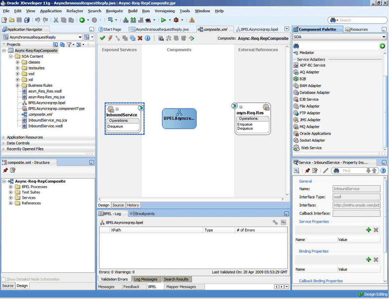
Description of "Figure 10-81 The JDeveloper Page - Composite.xml Page"
10.6.4.5 Creating Another Outbound Adapter Service
Perform the following steps to create an adapter service that enqueues the response (report) messages.
10.6.4.6 Wiring Services and Activities
You have to assemble or wire the four components that you have created: Inbound adapter service, BPEL process, async-Req-Res, and Outbound adapter reference. Perform the following steps to wire the components:
10.6.4.7 Deploying with JDeveloper
You must deploy the application profile for the SOA project and application you created in the earlier steps.
For more information about deploying the application profile using JDeveloper, see Deploying Oracle JCA Adapter Applications from .
You must also create an application server connection. For more information about creating an application server connection, see Creating an Application Server Connection for Oracle JCA Adapters.
10.6.4.8 Monitoring Using the Fusion Middleware Control Console
You can monitor the deployed SOA composite using the Fusion Middleware Control Console. Perform the following steps:
- Log in to http://servername:portnumber/em using your username/password. The Oracle Fusion Middleware Control page is displayed.
- In the left pane, navigate to SOA, soa-infra (soa_server1). A list of all the composites that are deployed appears.
- Click Async-Req-RepComposite[1.0]. The Async-Req-RepComposite[1.0] page is displayed.
- Put a message that has the content that conforms to the address-csv.xsd and also contains the Reply Queue as the header in the test_in queue.
- Wait for some time and then refresh the Fusion Middleware Control Console. An instance appears on the console. This is the instance that was triggered because of the processing that occurred.
- Click the Instances tab.
- Click the instance associated with this deployment. The Flow Trace page is displayed.
- Click the BPELAsyncreqrep component instance. The Audit Trail page is displayed.
- Click the Flow tab to debug the instance. The BPEL process instance flow is displayed.
- Click an activity to view the relevant payload details.
10.6.5 Outbound Dequeue
This use case is the end-to-end demonstration of how MQ Adapter dequeues a single message at a time. This section contains the following topics:
10.6.5.1 Prerequisites
To perform the outbound dequeue use case, you require the following files from the Adapters-101MQAdapterDequeueEnqueue sample:
-
De-queueEn-queue/De-queueEn-queueComposite/xsd/singleString.xsd
You also require the following files from the artifacts.zip file contained in the Adapters-101MQAdapterDequeueEnqueue sample:
-
artifacts/input/data.txt
You can onbtain the Adapters-101MQAdapterDequeueEnqueue sample by accessing the Oracle SOA Sample Code site.
You must also create a queue named test_out.
10.6.5.2 Designing the SOA Composite
You must create a JDeveloper application to contain the SOA composite. To create an application and a project for the use case, perform the following:
10.6.5.3 Creating an Outbound Dequeue Adapter Service
Perform the following steps to create an adapter service that dequeues the message to a queue:
10.6.5.4 Wiring Services and Activities
You have to assemble or wire the three components that you have created: Client, BPEL process, and Outbound adapter reference. Perform the following steps to wire the components:
10.6.5.5 Deploying with JDeveloper
You must deploy the application profile for the SOA project and application you created in the earlier steps.
For more information about deploying the application profile using JDeveloper, see Deploying Oracle JCA Adapter Applications from .
You must also create an application server connection. For more information about creating an application server connection, see Creating an Application Server Connection for Oracle JCA Adapters.
10.6.6 Configuring a Backout Queue
This use case demonstrates how a backout queue must be configured for Oracle MQ Series Adapter. Oracle MQ Series Adapter dequeues a message and enqueues the same message after transformation from the MQ Series queue. During this process, a failure can occur either during an invoke activity or when a response is being sent. You must configure a Backout Queue to send the rejected messages to a Backout Queue instead of the default rejected messages folder. This section contains the following topics:
10.6.6.1 Prerequisites
To perform the use case for configuring a backout queue, you must ensure that the adapter JNDI is configured for XA. Also, you require the singleString.xsd file, which you can create using the following code:
<schema attributeFormDefault="unqualified"
      elementFormDefault="qualified"
      targetNamespace="http://xmlns.oracle.com/singleString"
      xmlns="http://www.w3.org/2001/XMLSchema">
      <element name="singleString">
            <complexType>
                  <sequence>
                        <element name="input" type="string"/>
                  </sequence>
            </complexType>
      </element>
</schema>
10.6.6.2 Designing the SOA Composite
You must create a JDeveloper application to contain the SOA composite. To create an application and a project for the use case, perform the following:
10.6.6.3 Creating an Inbound Adapter Service
Perform the following steps to create an adapter service that dequeues the message from a queue:
10.6.6.4 Creating an Outbound Adapter Service
Perform the following steps to create an adapter service that enqueues the messages.
10.6.6.5 Wiring Services and Activities
You have to assemble or wire the three components that you have created: Inbound adapter service, BPEL process, and Outbound adapter reference. Perform the following steps to wire the components:
10.6.6.6 Deploying with JDeveloper
You must deploy the application profile for the SOA project and application you created in the earlier steps.
For more information about deploying the application profile using JDeveloper, see Deploying Oracle JCA Adapter Applications from .
You must also create an application server connection. For more information about creating an application server connection, see Creating an Application Server Connection for Oracle JCA Adapters.
10.6.7 CCDT Use Cases
You can configure the MQ Series Adapter to use CCDT for connection details; you can use the CCDT to connect to the first available queue manager from a list of queue managers.
For example, in this use case, there are three queue managers QM1, QM2 and QM3 with the basic properties as indicated in the table bekow.
The MQ adapter can, dynamically at runtime, connect to any of the three queue managers, depending on the one that is available (that is, if QM1 is down, the MQ adapter automatically connects to QM2; and if QM2 is also down, then the MQ Adapter must connect to QM3).
10.6.7.1 Example Queue Manager Properties and CCDT Configuration
Example queue manager properties are provided in this table.
| Queue Manager Name | QM1 | QM2 | QM3 |
|---|---|---|---|
|
Hostname |
localhost |
localhost |
10.177.255.25 |
|
PortName |
1414 |
2414 |
1414 |
|
Server Connection Channel Name |
channel.QM1 |
channel.QM2 |
channel.QM3 |
To achieve this, the CCDT must be configured as follows :
| Channel name | Queue manager name | Connection name |
|---|---|---|
|
channel.QM1 |
MyQM_group |
localhost(1414) |
|
channel.QM2 |
MyQM_group |
localhost(2414) |
|
channel.QM3 |
MyQM_group |
10.177.255.25(1414) |
10.6.7.2 Configuringa ConnectionFactoryJNDI
Once you have created a CCDT, a single ConnectionFactory JNDI must be configured to use this CCDT. The following ConnectionFactory properties must be configured in that JNDI:
-
CCDTurl -
QueueManagerName
10.6.7.3 Configuring the CCDTurl
The CCDTurl must point to the URL of the CCDT file that is used by the MQ Series Adapter to supply client connection details. For example, the values provided can be either of:
-
file:/scratch/username/ccdt/AMQCLCHL.TAB -
ftp://userName:password@myServer/definitionPath/AMQCLCHL.TAB
10.6.7.4 Configuring the QueueManagerName
In the use case, the value of the QueueManagerName property must be set to MyQM_group.
This name indicates that MQ Series Adapter should connect to the first available queue manager which has a client definition entry in the CCDT having Queue manager name as MyQM_group.
The property QueueManagerName is matched against the queue manager name defined in the CCDT and not the actual queue manager name. In general, the QueueManagerName should be provided appropriate values, using the considerations listed below:
-
If you only specify a queue manager name, for example
QM_default, the CCDT will be searched in alphabetical order for a client channel that contains in its definition a QueueManager name that matches exactly (and is case sensitive) to the one specified -
If an asterisk is included at the beginning of the specified queue manager name, for example
QM_default, then the CCDTis searched in alphabetical order of channel name, for an entry that matches the queue manager name with or without the asterisk. If two or more client channel definitions have the queue manager names defined as QM_default, then the first available queue manager is connected to. -
If the queue manager name is not specified in the CCDT, then the Queue Manager name in the JNDI should be a "*".
These two properties are the only required configuration for informing the MQ Series Adapter to use CCDT for connection details. The use of CCDT does not affect the configuration required for other MQ adapter features such as support for SSL, Exits or XA
If other ConnectionFactory properties such as Hostname, PortNumber, ChannelName are configured and the CCDT is also configured, the CCDT will take precedence over the those properties.
Once these ConnectionFactory properties are set, and this JNDI is used in any composite process, the MQ Adapter connects to the first available queue manager from QM1, QM2 and QM3.
10.6.8 Reading Single or Multiple RFH2 Rules and Formatting Header Version 2 Headers
You can dequeue and read MQ messages that contain single or multiple RFH2 headers, in addition to enqueueing messages with multiple RFH2 headers. Ths feature includes the following functionality:
-
Reading and writing the properties from the fixed portion of the RFH2 headers.
-
Reading and writing multiple occurrences of any individual folder within any RFH2 header.
-
Reading and writing multiple RFH2 header occurrences in a single message.
The RFH2 header enables the message producer to add more header properties to the payload and to provide other additional information.
By providing the MQ adapter the ability to read and write this information as header properties, you can perform specific processing of the message payload depending on the RFH2 header properties.
The following use cases provide examples of two types of scenarios.
10.6.8.1 Inbound and Outbound with Multiple RFH2 Headers on Both Sides
This sample demonstrates the use of the MQ Adapter for processing MQ messages containing one or more RFH2 headers.
An MQ message containing two RFH2 headers is dequeued from a queue and a new message with the same payload, but with updated RFH2 headers is enqueued to another queue.
The steps for creating this use case sample include:
10.6.8.1.1 Designing the SOA Composite
You must create a JDeveloper application to contain the SOA composite. To create an application and a project for the use case, perform the following:
10.6.8.1.2 Creating an Inbound Adapter Service
Perform the following steps to create an adapter service that dequeues the message and put the message to a queue:
- Drag and drop MQ Adapter from the Components window into the Exposed Services swim lane. The Adapter Configuration Wizard Welcome page is displayed.
- Click Next. The Service Name page is displayed.
- Enter
InboundMQin the Service Name field, and click Next. The MQ Series Connection page is displayed. - Accept the default JNDI name for the MQ Series connection, and click Next. The Adapter Interface page is displayed.
- Select Define from operation and schema (specified later), and click Next. The Operation Type page is displayed.
- Select Get Message from MQ (do not check Synchronous), and click Next. The Get Message from MQ page is displayed.
- Enter
queue1in the Queue Name field, select Choose Other Schema, click Next. The Messages page is displayed. - Select Native Format is not required (Schema is opaque), and click Next. The Finish page is displayed.
- Click Finish. You have now configured the inbound adapter service, and the composite.xml page is displayed with an inbound adapter added.
10.6.8.1.4 Wiring Services and Activities
You have to assemble or wire the three components that you have created: Inbound adapter service, BPEL process, and Outbound adapter reference. Perform the following steps to wire the components:
-
Drag the small triangle in the InboundMQ in the ExposedServices area to the drop zone that appears as a green triangle in DequeueEnqueueRFH2 in the Components area.
-
Drag the small triangle in DequeuEnqueueRFH2 in the Components area to the drop zone that appears as a green triangle in OutboundMQ in the External References area.
The composite.xml page is displayed, as shown in Figure 10-90.
Figure 10-99 The JDeveloper - Composite.xml Page
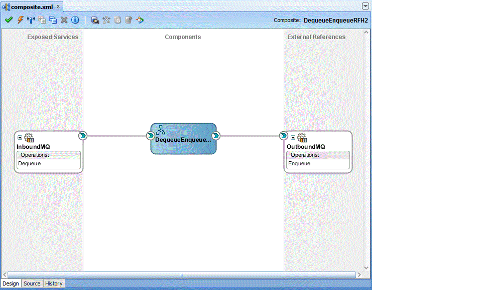
Description of "Figure 10-99 The JDeveloper - Composite.xml Page" -
Click File, Save All.
-
Double-click DequeueEnqueueRFH2. The DequeueEnqueueRFH2.bpel page is displayed.
-
Drag and drop the Receive, Assign and Invoke activities in the order mentioned from the Components windowto the Components area. The JDeveloper DequeueEnqueueRFH2.bpel page is displayed.
Figure 10-100 The DequeueEnqueueRFH2.bpel Page"
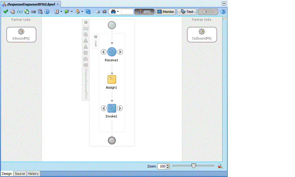
Description of "Figure 10-100 The DequeueEnqueueRFH2.bpel Page"" -
Drag and drop the Receive activity to the Inbound Service. The Receive dialog is displayed.
-
Click the AutoCreate Variable icon that appears at the end of the Variable field. The Create Variable dialog is displayed.
-
Accept the defaults, and click OK.
-
Click the Create Instance box, and click OK.
-
Drag and drop the Invoke activity to the Outbound Service. The Invoke dialog is displayed.
-
Click the Automatically Create Input Input Variable icon that appears at the end of the Input Variable field.
-
Accept the defaults, and click OK. The Invoke dialog is displayed.
-
Click OK.
-
Double-click the Assign activity. The Assign dialog is displayed.
-
Select the variables, and click the Plus icon.
-
Click OK in the Assign dialog. The JDeveloper
DequeueEnqueueRFH2.bpel.htmlis displayed.Figure 10-102 The DequeueEnqueueRFH2.bpel page
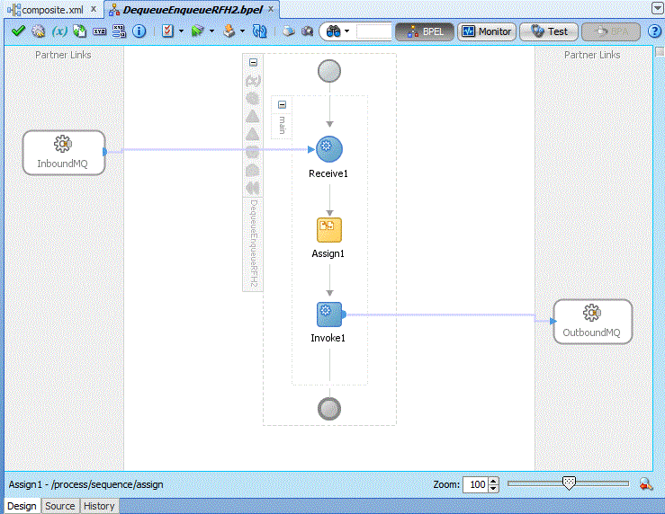
Description of "Figure 10-102 The DequeueEnqueueRFH2.bpel page" -
Create temporary variables to store the RFH2 header portions.
-
Open the Source tab of the
DequeueEnqueueRFH2.bpelpage. -
Under the <variables> tab add the following new variables:
    <variable name="RFH2.StructId" type="xsd:string"/>
    <variable name="RFH2.Version" type="xsd:string"/>
    <variable name="RFH2.Encoding" type="xsd:string"/>
    <variable name="RFH2.CodedCharSetId" type="xsd:string"/>
    <variable name="RFH2.Format" type="xsd:string"/>
    <variable name="RFH2.Flags" type="xsd:string"/>
    <variable name="RFH2.NameValueCCSID" type="xsd:string"/>
    <variable name="RFH2.JMSFolder" type="xsd:string"/>
    <variable name="RFH2.MCDFolder" type="xsd:string"/>
    <variable name="RFH2.USRFolder" type="xsd:string"/>
    <variable name="RFH2.USRFolder_2" type="xsd:string"/>
    <variable name="RFH2.PSCFolder" type="xsd:string"/>
    <variable name="RFH2extrafolder" type="xsd:string"/>
    <variable name="RFH2_2.StructId" type="xsd:string"/>
    <variable name="RFH2_2.Version" type="xsd:string"/>
    <variable name="RFH2_2.Encoding" type="xsd:string"/>
    <variable name="RFH2_2.CodedCharSetId" type="xsd:string"/>
    <variable name="RFH2_2.Format" type="xsd:string"/>
    <variable name="RFH2_2.Flags" type="xsd:string"/>
    <variable name="RFH2_2.NameValueCCSID" type="xsd:string"/>
    <variable name="RFH2_2.JMSFolder" type="xsd:string"/>
    <variable name="RFH2_2.JMSFolder_2" type="xsd:string"/>
    <variable name="RFH2_2.MCDFolder" type="xsd:string"/>
    <variable name="RFH2_2.USRFolder" type="xsd:string"/>
    <variable name="RFH2_2.USRFolder_2" type="xsd:string"/>
    <variable name="RFH2_2.PSCFolder" type="xsd:string"/>
    <variable name="TotalRFH2" type="xsd:string"/>
-
-
Configure the Receive Activity to receive RFH2 header properties in the temporary variables created.
-
Open the Source tab of the
DequeueEnqueueRFH2.bpelpage. -
Under the <receive> tag add the following entries.
<bpelx:property name="jca.mq.RFH2.StructId" variable="RFH2.StructId"/>
<bpelx:property name="jca.mq.RFH2.Version" variable="RFH2.Version"/>
<bpelx:property name="jca.mq.RFH2.Encoding" variable="RFH2.Encoding"/>
<bpelx:property name="jca.mq.RFH2.CodedCharSetId"     variable="RFH2.CodedCharSetId"/>
<bpelx:property name="jca.mq.RFH2.Format" variable="RFH2.Format"/>
<bpelx:property name="jca.mq.RFH2.Flags" variable="RFH2.Flags"/>
<bpelx:property name="jca.mq.RFH2.NameValueCCSID"     variable="RFH2.NameValueCCSID"/>
<bpelx:property name="jca.mq.RFH2.JMSFolder" variable="RFH2.JMSFolder"/>
<bpelx:property name="jca.mq.RFH2.MCDFolder" variable="RFH2.MCDFolder"/>
<bpelx:property name="jca.mq.RFH2.USRFolder" variable="RFH2.USRFolder"/>
<bpelx:property name="jca.mq.RFH2.USRFolder_2" variable="RFH2.USRFolder_2"/>
<bpelx:property name="jca.mq.RFH2.PSCFolder" variable="RFH2.PSCFolder"/>
<bpelx:property name="jca.mq.RFH2.mq_usr" variable="RFH2extrafolder"/>
<bpelx:property name="jca.mq.RFH2_2.StructId" variable="RFH2_2.StructId"/>
<bpelx:property name="jca.mq.RFH2_2.Version" variable="RFH2_2.Version"/>
<bpelx:property name="jca.mq.RFH2_2.Encoding" variable="RFH2_2.Encoding"/>
<bpelx:property name="jca.mq.RFH2_2.CodedCharSetId"      variable="RFH2_2.CodedCharSetId"/>
<bpelx:property name="jca.mq.RFH2_2.Format" variable="RFH2_2.Format"/>
<bpelx:property name="jca.mq.RFH2_2.Flags" variable="RFH2_2.Flags"/>
<bpelx:property name="jca.mq.RFH2_2.NameValueCCSID" variable=     "RFH2_2.NameValueCCSID"/>
<bpelx:property name="jca.mq.RFH2_2.JMSFolder" variable="RFH2_2.JMSFolder"/>
<bpelx:property name="jca.mq.RFH2_2.JMSFolder_2"      variable="RFH2_2.JMSFolder_2"/>
<bpelx:property name="jca.mq.RFH2_2.MCDFolder" variable="RFH2_2.MCDFolder"/>
<bpelx:property name="jca.mq.RFH2_2.USRFolder" variable="RFH2_2.USRFolder"/>
<bpelx:property name="jca.mq.RFH2_2.PSCFolder" variable="RFH2_2.PSCFolder"/>
<bpelx:property name="jca.mq.RFH2_2.USRFolder_2"     variable="RFH2_2.USRFolder_2"/>
<bpelx:property name="jca.mq.RFH2.Total.Headers" variable="TotalRFH2"/>
-
-
Configure the Invoke activity to push modified RFH2 header properties to the outbound message.
-
Open the Source tab of the DequeueEnqueueRFH2.bpel page
-
Under the <invoke> tag add the following entries
<bpelx:inputProperty name="jca.mq.MQMD.Format" expression="'RF_HDR_2'"/> <bpelx:inputProperty name="jca.mq.RFH2.StructId" variable="RFH2.StructId"/> <bpelx:inputProperty name="jca.mq.RFH2.Version" variable="RFH2.Version"/> <bpelx:inputProperty name="jca.mq.RFH2.CodedCharSetId" variable="RFH2.CodedCharSetId"/> <bpelx:inputProperty name="jca.mq.RFH2.Encoding" variable="RFH2.Encoding"/> <bpelx:inputProperty name="jca.mq.RFH2.Flags" variable="RFH2.Flags"/> <bpelx:inputProperty name="jca.mq.RFH2.Format" expression="'MQHRF2 '"/> <bpelx:inputProperty name="jca.mq.RFH2.NameValueCCSID" variable="RFH2.NameValueCCSID"/> <bpelx:inputProperty name="jca.mq.RFH2.JMSFolder" variable="RFH2.JMSFolder"/> <bpelx:inputProperty name="jca.mq.RFH2.MCDFolder" variable="RFH2.MCDFolder"/> <bpelx:inputProperty name="jca.mq.RFH2.USRFolder" variable="RFH2.USRFolder"/> <bpelx:inputProperty name="jca.mq.RFH2.mq_usr" variable="RFH2extrafolder"/> <bpelx:inputProperty name="jca.mq.RFH2_2.StructId" expression="'RFH '"/> <bpelx:inputProperty name="jca.mq.RFH2_2.Version" expression="'2'"/> <bpelx:inputProperty name="jca.mq.RFH2_2.CodedCharSetId" expression="'819'"/> <bpelx:inputProperty name="jca.mq.RFH2_2.Encoding" expression="'273'"/> <bpelx:inputProperty name="jca.mq.RFH2_2.Flags" expression="'0'"/> <bpelx:inputProperty name="jca.mq.RFH2_2.Format" expression="'MQSTR '"/> <bpelx:inputProperty name="jca.mq.RFH2_2.NameValueCCSID" expression="'1208'"/> <bpelx:inputProperty name="jca.mq.RFH2_2.JMSFolder" expression="'<jms><Dst>MYTOPIC</Dst><Exp>2000</Exp><Pri>4</Pri><Cid>22344</Cid><Rto>REPLY.QUEUE</Rto><Gid>3334</Gid><Seq>2</Seq><Dlv>1</Dlv><xxx>UserSpace</xxx></jms>'"/> <bpelx:inputProperty name="jca.mq.RFH2_2.JMSFolder_2" variable="RFH2_2.JMSFolder_2"/> <bpelx:inputProperty name="jca.mq.RFH2_2.MCDFolder" expression="'<mcd><Msd>jms_object</Msd></mcd>'"/> <bpelx:inputProperty name="jca.mq.RFH2_2.USRFolder" variable="RFH2_2.USRFolder"/> <bpelx:inputProperty name="jca.mq.RFH2_2.USRFolder_2" variable="RFH2_2.USRFolder_2"/>
-
-
Click File, Save All.
10.6.8.1.5 Deploying with JDeveloper
You must deploy the application profile for the SOA project and application you created in the earlier steps.
For more information about deploying the application profile using JDeveloper, see Deploying Oracle JCA Adapter Applications from .
You must also create an application server connection. For more information about creating an application server connection, see Creating an Application Server Connection for Oracle JCA Adapters.
You must place the MQ message with the correct RFH2 headers in the inbound queue.
The sample is configured to obtain two RFH2 headers from the inbound message (this can be changed by configuring the BPEL process as required). The test input MQ message should have the following:
-
Payload: Any message (any format will be acceptable becaise we are using Opaque)
-
RFH2 header 1: Should contain 2 USR folders, 1 JMS folder, 1 PSC folder, 1 MCD folder and 1 mq_usr folder.
-
RFH2 header 2: Should contain 2 USR folders, 2 JMS folders, 1 PSC folder and 1 MCD folder.
Deploy the sample and put the message to the inbound queue. Check the outbound queue for a new message having modified RFH2 headers (as configured in the BPEL invoke activity)
10.6.8.2 Outbound Dequeue with Multiple RFH2 Headers
This sample demonstrates the use of the MQ Adapter for obtaining MQ messages containing one or more RFH2 headers in an outbound dequeue scenario.
In this sample, an MQ message containing two RFH2 headers is dequeued from a queue in the outbound queue scenario.
The steps for creating this use case sample include:
10.6.8.2.1 Designing the SOA Composite
You must create a JDeveloper application to contain the SOA composite. To create an application and a project for the use case, perform the following:
10.6.8.2.2 Creating an Outbound Dequeue Adapter Service
Perform the following steps to create an adapter service that dequeues the message to a queue:
10.6.8.2.3 Wiring Services and Activities
You must assemble or wire the three components that you have created: Client, BPEL process, and OutboundDQ adapter reference.
Perform the following steps to wire the components:
-
Drag the small triangle in the BPEL process in the Components area to the drop zone that appears as a green triangle in the OutboundDequeueService in the External References area.
-
Double-click the OutboundDequeueRFH2 bpel process. The OutboundDequeueRFH2.bpel page is displayed.
The JDeveloper Composite.xml appears, as shown in Figure 10-106.
Figure 10-104 The JDeveloper - Composite.xml
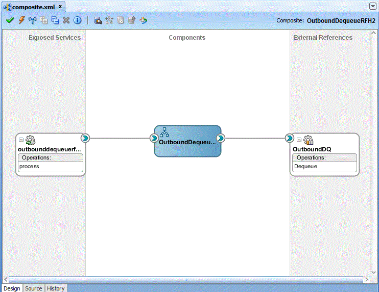
Description of "Figure 10-104 The JDeveloper - Composite.xml" -
Click File, Save All.
-
Double-click OutboundDequeueRFH2.bpel. The OutboundDequeueRFH2.bpel page is displayed.
-
Drag and drop the Invoke and Assign activities in the order mentioned from the Components window to the Components area in between the
receiveInputandreplyOutputactivities. -
Drag and drop the Invoke activity to the OutboundDQ adapter reference. The Invoke dialog is displayed.
-
Click the Auto Create Variable icon that appears at the end of the Variable field. The Create Variable dialog is displayed.
-
Accept the defaults, and click OK.
-
Repeat the same for the output variable and click OK.
-
Double-click the Assign activity. The Assign dialog is displayed.
-
Select the variables, and click the Plus icon.
-
.Click OK in the Assign dialog. The JDeveloper
BPELOutboundDequeue.bpelpage is displayed.Figure 10-106 The JDeveloper BPELOutboundDequeue.bpel page
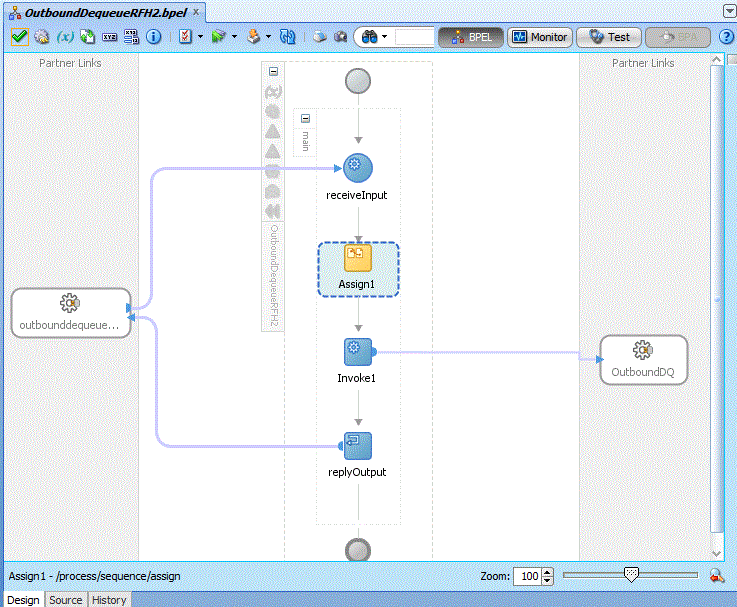
Description of "Figure 10-106 The JDeveloper BPELOutboundDequeue.bpel page" -
Create temporary variables to store the RFH2 header portions.
-
Open the Source tab of the DequeueEnqueueRFH2.bpel page.
-
Under the <variables> tab add the following new variables.
    <variable name="RFH2.StructId" type="xsd:string"/>
    <variable name="RFH2.Version" type="xsd:string"/>
    <variable name="RFH2.Encoding" type="xsd:string"/>
    <variable name="RFH2.CodedCharSetId" type="xsd:string"/>
    <variable name="RFH2.Format" type="xsd:string"/>
    <variable name="RFH2.Flags" type="xsd:string"/>
    <variable name="RFH2.NameValueCCSID" type="xsd:string"/>
    <variable name="RFH2.JMSFolder" type="xsd:string"/>
    <variable name="RFH2.MCDFolder" type="xsd:string"/>
    <variable name="RFH2.USRFolder" type="xsd:string"/>
    <variable name="RFH2.USRFolder_2" type="xsd:string"/>
    <variable name="RFH2.PSCFolder" type="xsd:string"/>
    <variable name="RFH2extrafolder" type="xsd:string"/>
    <variable name="RFH2_2.StructId" type="xsd:string"/>
    <variable name="RFH2_2.Version" type="xsd:string"/>
    <variable name="RFH2_2.Encoding" type="xsd:string"/>
    <variable name="RFH2_2.CodedCharSetId" type="xsd:string"/>
    <variable name="RFH2_2.Format" type="xsd:string"/>
    <variable name="RFH2_2.Flags" type="xsd:string"/>
    <variable name="RFH2_2.NameValueCCSID" type="xsd:string"/>
    <variable name="RFH2_2.JMSFolder" type="xsd:string"/>
    <variable name="RFH2_2.JMSFolder_2" type="xsd:string"/>
    <variable name="RFH2_2.MCDFolder" type="xsd:string"/>
    <variable name="RFH2_2.USRFolder" type="xsd:string"/>
    <variable name="RFH2_2.USRFolder_2" type="xsd:string"/>
    <variable name="RFH2_2.PSCFolder" type="xsd:string"/>
    <variable name="TotalRFH2" type="xsd:string"/>
-
-
Configure the Invoke Activity to receive the RFH2 header properties from the outbound dequeue message.
-
Open the Source tab of the DequeueEnqueueRFH2.bpel page.
-
Under the <invoke> tag add the following entries.
<bpelx:outputProperty name="jca.mq.RFH2.StructId" variable="RFH2.StructId"/>
      <bpelx:outputProperty name="jca.mq.RFH2.Version" variable="RFH2.Version"/>
      <bpelx:outputProperty name="jca.mq.RFH2.Encoding" variable="RFH2.Encoding"/>
      <bpelx:outputProperty name="jca.mq.RFH2.CodedCharSetId" variable="RFH2.CodedCharSetId"/>
      <bpelx:outputProperty name="jca.mq.RFH2.Format" variable="RFH2.Format"/>
      <bpelx:outputProperty name="jca.mq.RFH2.Flags" variable="RFH2.Flags"/>
      <bpelx:outputProperty name="jca.mq.RFH2.NameValueCCSID" variable="RFH2.NameValueCCSID"/>
      <bpelx:outputProperty name="jca.mq.RFH2.JMSFolder" variable="RFH2.JMSFolder"/>
      <bpelx:outputProperty name="jca.mq.RFH2.MCDFolder" variable="RFH2.MCDFolder"/>
      <bpelx:outputProperty name="jca.mq.RFH2.USRFolder" variable="RFH2.USRFolder"/>
      <bpelx:outputProperty name="jca.mq.RFH2.USRFolder_2" variable="RFH2.USRFolder_2"/>
      <bpelx:outputProperty name="jca.mq.RFH2.PSCFolder" variable="RFH2.PSCFolder"/>
      <bpelx:outputProperty name="jca.mq.RFH2.mq_usr" variable="RFH2extrafolder"/>
      <bpelx:outputProperty name="jca.mq.RFH2_2.StructId" variable="RFH2_2.StructId"/>
      <bpelx:outputProperty name="jca.mq.RFH2_2.Version" variable="RFH2_2.Version"/>
      <bpelx:outputProperty name="jca.mq.RFH2_2.Encoding" variable="RFH2_2.Encoding"/>
      <bpelx:outputProperty name="jca.mq.RFH2_2.CodedCharSetId" variable="RFH2_2.CodedCharSetId"/>
      <bpelx:outputProperty name="jca.mq.RFH2_2.Format" variable="RFH2_2.Format"/>
      <bpelx:outputProperty name="jca.mq.RFH2_2.Flags" variable="RFH2_2.Flags"/>
      <bpelx:outputProperty name="jca.mq.RFH2_2.NameValueCCSID" variable="RFH2_2.NameValueCCSID"/>
      <bpelx:outputProperty name="jca.mq.RFH2_2.JMSFolder" variable="RFH2_2.JMSFolder"/>
      <bpelx:outputProperty name="jca.mq.RFH2_2.JMSFolder_2" variable="RFH2_2.JMSFolder_2"/>
      <bpelx:outputProperty name="jca.mq.RFH2_2.MCDFolder" variable="RFH2_2.MCDFolder"/>
      <bpelx:outputProperty name="jca.mq.RFH2_2.USRFolder" variable="RFH2_2.USRFolder"/>
      <bpelx:outputProperty name="jca.mq.RFH2_2.PSCFolder" variable="RFH2_2.PSCFolder"/>
      <bpelx:outputProperty name="jca.mq.RFH2_2.USRFolder_2" variable="RFH2_2.USRFolder_2"/>
      <bpelx:outputProperty name="jca.mq.RFH2.Total.Headers" variable="TotalRFH2"/>
-
-
Click File, Save All.
10.6.8.2.4 Deploying with JDeveloper
You must deploy the application profile for the SOA project and application you created in the earlier steps.
For more information about deploying the application profile using JDeveloper, see Deploying Oracle JCA Adapter Applications from .
You must also create an application server connection. For more information about creating an application server connection, see Creating an Application Server Connection for Oracle JCA Adapters.
The MQ message with the correct RFH2 headers must be put to the outbound dequeue queue. The sample is configured to obtain two RFH2 headers from the message (this can be changed by configuring the bpel process as required). The test MQ message should have the following:
-
Payload: Any message (any format will do since Opaque is being employed)
-
RFH2 header 1: Should contain 2 USR folders, 1 JMS folder, 1 PSC folder, 1 MCD folder and 1 mq_usr folder.
-
RFH2 header 2: Should contain 2 USR folders, 2 JMS folders, 1 PSC folder and 1 MCD folder.
Deploy the sample and put the message to the outbound dequeue queue. Open the Fusion Middleware Control console and invoke the sample using the Test utility. Wait for a time and examine the instance audit trail.
10.6.9 Processing Messages as Attachment
This section demonstrates how to configure the inbound and outbound MQ Adapter to process messages as attachments.
10.6.9.1 Designing the SOA Composite
You must create a JDeveloper application to contain the SOA composite. To create an ‘ application and a project for the use case, perform the following:
- In JDeveloper, click File, select New and then select Application. The New Gallery dialog is displayed.
- Expand the General node, and select the Applications category.
- In the Items list, select SOA Application and click OK. The Create SOA Application Wizard is displayed.
- In the Name Your Application screen, enter
MQAsAttachmentin the Application Name field, and then click Next. The Name Your Project screen is displayed. - In the Project Name field, enter MQAsAttachment and click Next. The Configure SOA Settings screen is displayed.
- In the Composite Template list, select Composite With BPEL, and then click Finish. The Wizard displays the Create BPEL Process dialog.
- Enter
MQAsAttachmentin the Name field, and select Define Service Later from the Template box. - Click OK. The
MQAsAttachmentapplication and theMQAsAttachmentproject appears in the design area.
10.6.9.2 Creating an Inbound Adapter Service
Perform the following steps to create an adapter service that dequeues the message from a queue:
10.6.9.4 Wiring Services and Activities
You have to assemble or wire the three components that you have created: Inbound adapter service, BPEL process, and Outbound adapter reference. Perform the following steps to wire the components:
10.6.9.5 Deploying with JDeveloper
You must deploy the application profile for the SOA project and the application you created in the preceding steps. To deploy the application profile using JDeveloper, perform the following steps:
- Create an application server connection. For more information, see Creating an Application Server Connection for Oracle JCA Adapters.
- Deploy the application. For more information, see Deploying Oracle JCA Adapter Applications from .

