C H A P T E R  1

Introduction to the Sun Blade 6000 Disk Module

This chapter contains an overview of the Sun Blade 6000 Disk Module (also called a disk blade) and contains the following topics:


Features of the Disk Module

The Sun Blade 6000 Disk Module is a blade for the Sun Blade 6000 Modular System that contains disks. It communicates with server blades through Network Express Modules that support SAS, specifically the Sun Blade 6000 Multi-Fabric NEM and the Sun Blade 6000 10GbE Multi-Fabric NEM.

TABLE 1-1 summarizes the features of the disk module.


TABLE 1-1    Features of the Sun Blade 6000 Disk Module 
Feature Specifications
Disk Drives Eight total with front panel access. The storage blade supports SAS or Solid State (SSD) disk drives.
Types SAS (2.5 inch or 63.5 mm).
Disk Drive Bracket Sun disk drive mounting bracket.
Management 2 Arm7-S Processors (SAS expander devices).

2MB SRAM code storage, 2MB FLASH, 8K Serial EEPROM.

Data Rates 1.5 and 3.0 Gbit/sec. SAS with auto-negotiation.

Two 1x or one 2x wide connections into blade. 12 Gbit/sec total.

Protocols SAS - Serial Attached SCSI - v1.0, v1.1.

SSP - Serial SCSI Protocol.

SMP - Serial Management Protocol.

SES - SCSI Enclosure Services.

Indicators SIS indicators: Activity and Fault for drives and blade. Locate for blade only.
Health Voltage monitoring, temperature monitoring, disk fault detection, and blade fault detection.

TABLE 1-1 summarizes the physical specifications of the disk module.


TABLE 1-2   Sun Blade 6000 Server Module Physical and Environmental Specifications
Specification Value
Width 12.87 inches (327 mm)
Height 1.7 inches (44 mm)
Depth 20.16 inches (512 mm)
Weight 17 pounds (8 kg)
Power 240W Max (estimated)
Environmental Humidity: 10% to 90% non-condensing

Temperature: 5 to 40 deg C operating (-40 to 70 deg C storage)

Altitude: 0 to 10,000 ft (3,048 meters)

Power Supplies 3.3V_AUX from chassis backplane.

12V from chassis backplane.

Other voltages generated on blade.

Cooling Front-to-back forced air (no internal fans).
Regulatory UL/CSA

FCC part15 Class A


Sun Blade 6000 Disk Module Orientation

This section contains illustrations that you can use to become familiar with the Sun Blade 6000 disk module.
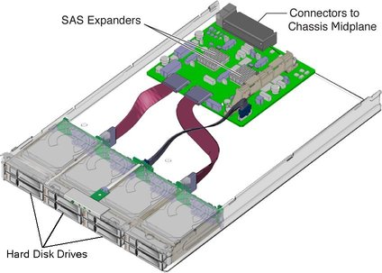
FIGURE 1-1   Interior of the Sun Blade 6000 Disk Blade

Illustration showing the interior of the disk
blade.


FIGURE 1-2 shows the features of the front panel.
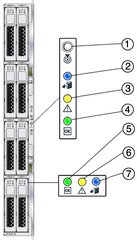
FIGURE 1-2   Sun Blade 6000 Disk Module Front Panel

Illustration showing a front view of the disk
module with its LEDs


TABLE 1-3   Front Panel LED Functions
LED Name Description
1 Combined Locate button and LED (white) This LED helps you to identify which system in the rack you are working on in a rack full of servers.
  • Push and release this button to make the Locate LED blink for 30 minutes.

  • When Locate LED is blinking, push and release this button to make the Locate LED stop blinking.

  • Hold down the button for 5 seconds to initiate a “push-to-test” mode that illuminates all other LEDs for 15 seconds.

  • This LED can also be made to blink from a remote system using the CMM ILOM. Refer to the Sun Blade 6000 Disk Module Administration Guide for details.

2 Ready-to-Remove LED (blue) Not used.
3 Module Fault LED (amber) This LED has two states:
  • On: An event has been acknowledged, and service action is required.

  • Off: Normal operation.

4 Module Activity LED (green) This LED has three states:
  • Off: Module is offline.

  • On: Module is online.

  • Slow blinking (1 Hz at 50% duty cycle): Module is booting or configuring (firmware flash update in progress).

5 Disk Drive OK LED (green) This LED has three states:
  • On: Power is on and disk is online.

  • Off: Disk is offline.

  • Blinking: Irregular blinking means normal disk activity; steady, slow blink means a RAID volume is rebuilding on this disk.

6 Disk Drive Fault and Locate LED (amber) This LED has four states:
  • On: Disk fault. Service action required.

  • Off: Normal operation.

  • Slow blink: Disk failure predicted.

  • Fast blink: Locate function activated.

7 Ready-to-Remove LED (blue) Not used.

The events that can cause a disk blade’s Module Fault LED (amber) to turn on are:


CRUs and FRUs

For the Sun Blade 6000 Disk Module, the Customer Replaceable Units (CRUs) are the disks in the disk module. There is only one Field Replaceable Unit (FRU), which is the disk module itself.

If either a disk or a disk module fails, you must replace it, because there are no replaceable subassemblies.

You can replace the disks and the disk blade yourself.


What’s in This Document

The remainder of the document includes these topics:

Chapter 2: This chapter contains information and procedures for servicing the Sun Blade 6000 disk module hardware, including component removal and replacement procedures.

Chapter 3: This chapter describes the procedures for replacing a Sun Blade disk module.

Chapter 4: This chapter describes the procedures for replacing an LSI host bus adapter on a server blade that is paired with a disk blade and restoring its configuration. This includes replacing the server blade when the host bus adapter is embedded in it.

Appendix A: This appendix provides instructions for reactivating inactive RAID volumes.

Appendix B: This appendix provides instructions information on where to obtain the lsiutil software and how to use it.