| C H A P T E R 3 |
|
Maintaining the Server |
This chapter contains information and procedures for servicing your modular server hardware, including component removal and replacement procedures.
The following topics are covered in this section:
You can monitor the status of system components through the service processor and the system status LEDs.
The following component information is available through the system service processor.
See the Embedded Lights Out Manager Administration Guide or the corresponding ILOM documentation collection for more information.
Your server module has external and internal system status LEDs.
FIGURE 3-1 shows the locations of the external status indicator LEDs.
FIGURE 3-1 External LED Location

Refer to TABLE 3-1 for descriptions of the LED behavior.
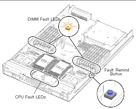
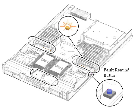
These servers have internal status indicator LEDs for the DIMM slots and the CPUs.
When the server module is removed from the chassis and the top cover removed, a fault indicator button can be pressed to view the location of the DIMM or CPU that has failed.
FIGURE 3-2 Fault Indicator Button
The server can be serviced with the following items:
Use the preparatory procedures in this section when you are referred to them from the removal and replacement procedures.
To replace components for the Sun Blade X6250 server module, with the exception of the hard disks, you need to remove the server module from the chassis. If you are only removing hard disks, you can skip this section and go to Replacing a Hard Disk.
1. Choose a method for shutting down the server from main power mode to standby power mode. See FIGURE 3-1 for the location of the power button.
From the ELOM or ILOM command prompt, type:
See the Embedded Lights Out Manager Administration Guide or the Sun Integrated Lights Out Manager 2.0 User’s Guide for more information.
When main power is off, the Power/OK LED on the front panel blink, indicating that the server is in standby power mode.
2. Turn off any peripheral devices connected to the dongle and disconnect the dongle from the server.
FIGURE 3-3 Removing a Server Module
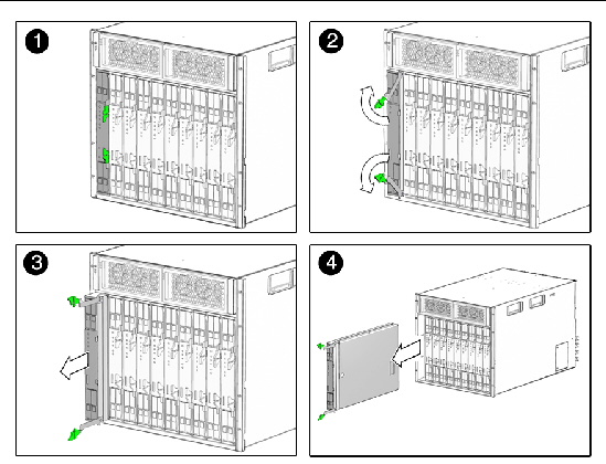
3. Remove the server module from the chassis. See FIGURE 3-3.
a. Press together and hold green ejector buttons.
b. Open the ejector levers by rotating them out from the server module
c. Pull the server module out from the chassis by the ejector levers until you are able to grasp the module with both hands to pull it out of the chassis.

|
Caution - The server module is heavy. Use two hands to remove it from the chassis, and be prepared to support the weight when it clears the chassis. |
4. Set the server module on an antistatic surface.

|
Caution - Do not operate the system with empty slots. Always insert a filler into an empty slot to reduce the possibility of module shutdown. |
1. Press down on the cover release button and, using the indent for leverage, slide the main cover toward the rear of the chassis approximately 0.5 inch (12 mm). See FIGURE 3-4.
2. Grasp the cover by its rear edge and lift it straight up from the chassis.
FIGURE 3-4 Removing the Main Cover
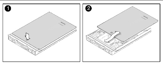
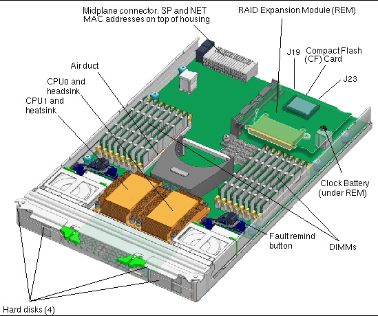
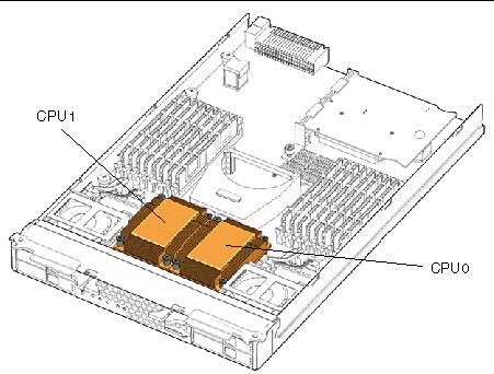
FIGURE 3-5 shows the locations of the replaceable components that are documented in this chapter.
FIGURE 3-5 Location of CPU Components
This section contains procedures for replacing the following components:
| Note - This component is a CRU and can be replaced by anyone. |
Supported components and their part numbers are subject to change over time. For the most up-to-date list of replaceable components for these servers, visit:
http://sunsolve.sun.com/handbook_pub/Systems/
1. Click on the name and model of your server.
2. On the product page that opens for the server, click on Full Components List for the list of components.
Use the following procedure to replace this component.
1. Power off the server and remove the server module from the chassis as described in Removing the Server Module From the Chassis.

|
Caution - Do not operate the system with empty slots. Always insert a filler into an empty slot to reduce the possibility of module shutdown. |
2. Remove the main cover as described in Removing the Main Cover.
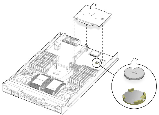
| Note - Note the orientation (polarity) of the battery in its holder before removing it. The positive polarity, marked with a “+” symbol, should be facing up. |
3. If a RAID expansion module is present, lift it out of the way.
The battery is under the RAID expansion module. See FIGURE 3-6.
See Adding or Replacing a RAID Expansion Module if required for additional information.
4. Remove the battery by gently pulling the clip away from the battery face and lifting the battery straight up. See FIGURE 3-6.
FIGURE 3-6 Removing the Battery
To install the battery, reverse Step 1 through Step 4.
1. If necessary, back up any data that is contained on the compact flash module.
2. Power off the server and remove the server module from the chassis as described in Removing the Server Module From the Chassis.

|
Caution - Do not operate the system with empty slots. Always insert a filler into an empty slot to reduce the possibility of module shutdown. |
3. Remove the main cover as described in Removing the Main Cover.
4. Locate the compact flash module under the REM at the back of the server module. See FIGURE 3-7.
FIGURE 3-7 Replacing the Compact Flash
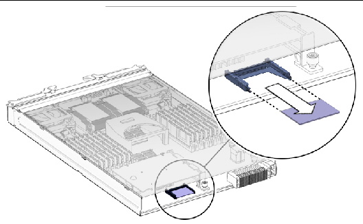
5. Grasp the module and pull it out.
Installation is the reverse of this procedure.
This section describes how to replace DIMMs. It provides the rules for populating DIMMs, and a procedure to replace them.
The DIMM population rules for the modular server are listed here:
TABLE 3-3 shows the relationships. The branches and slots, and the order in which they must be installed, appear in FIGURE 3-8.
| Note - A DIMM is a CRU and can be replaced by anyone. |
Supported components and their part numbers are subject to change over time. For the most up-to-date list of replaceable components for these servers, see the following URL:
http://sunsolve.sun.com/handbook_pub/Systems/
1. Click the name and model of your server.
2. On the product page that opens for the server, click on Full Components List for the list of components.
1. Power off the server and remove the server module from the chassis as described in Removing the Server Module From the Chassis.

|
Caution - Do not operate the system with empty slots. Always insert a filler into an empty slot to reduce the possibility of module shutdown. |
2. Remove the main cover as described in Removing the Main Cover.
3. Press the fault remind button on the motherboard to illuminate the LED for the DIMMs that have failed.
FIGURE 3-8 DIMM Slots and Fault Indicator Button
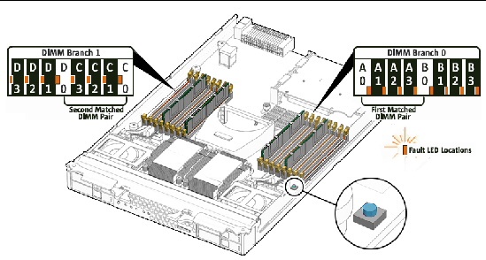
4. Locate the DIMM slot on the motherboard to which you will install or replace a DIMM.
LEDs next to the DIMMs indicate a faulty DIMM:
5. Before continuing with the next step, review the guidelines in DIMM Population Rules.
a. Rotate both DIMM slot ejectors outward as far as they will go.
The DIMM is partially ejected from the socket. See FIGURE 3-9.
b. Carefully lift the DIMM straight up to remove it from the socket.
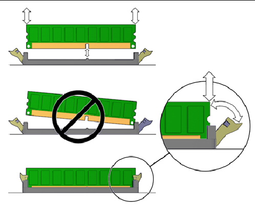
a. Ensure that the DIMM slot ejectors at each end of the memory socket are fully open (rotated outward) to accept the new DIMM.
b. Align the notch in the bottom edge of the DIMM with the key in the DIMM socket. See FIGURE 3-9.
c. Press down evenly on both top corners of the DIMM until the ejectors snap over the cutouts in the left and right edges of the DIMM.
The Intel Xeon processor on the Sun Blade X6250 server module provides parity protection on its internal cache memories and error-correcting code (ECC) protection of the data. The system can detect and log to the system event log (SEL) the following types of errors:
Advanced ECC corrects up to 4 bits in error on nibble boundaries, as long as they are all in the same DRAM. If a DRAM fails, the DIMM continues to function.
1. Power off the server and remove the server module from the chassis as described in Removing the Server Module From the Chassis.

|
Caution - Do not operate the system with empty slots. Always insert a filler into an empty slot to reduce the possibility of module shutdown. |
2. Remove the main cover as described in Removing the Main Cover.
3. Press the fault remind button on the motherboard to illuminate the LED for the CPU that has failed.
FIGURE 3-10 Fault Remind Button
4. Identify which CPU and heatsink you are replacing.
The internal designation of the two CPUs in the server is shown in FIGURE 3-10. There is a fault LED on the motherboard for each CPU:
5. Remove the heatsink from the motherboard:
a. Hold down on the top of the heatsink to prevent it from tipping unevenly while you alternately loosen the four spring-loaded mounting screws that secure the heatsink to the motherboard. Turn the screws 180 degrees at a time, then remove the screws when they are detached. See FIGURE 3-12.
FIGURE 3-12 Removing the Heatsink and CPU
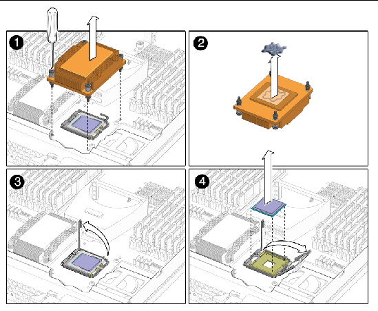
b. Twist the heatsink slightly to lift it off of the board. Turn the heatsink upside down and allow the spring in each of the four mounting holes to fall out into your hand.
| Note - Set the heatsink upside down on a clean, flat surface to prevent the thermal grease from contaminating other components. |
a. Pull the CPU socket lever slightly away from the socket.
b. Pivot the lever up, into the fully open position.
c. Open the hinged plate that covers the CPU until it is in the fully open position.
d. Lift the CPU out of the socket, leaving the lever and plate in the open position.
7. Install the new CPU, or reinstall the existing CPU (see FIGURE 3-13):
| Note - Mixing CPU speeds is not supported. Use two identical CPUs in your server. |
a. If you are reinstalling the existing CPU, use an alcohol pad to clean all the old thermal grease from the component surface.
You will need to apply new thermal grease when you reinstall the heat sink in Step 8.
b. Ensure that the CPU socket release lever and retainer plate are in the fully open position.
c. Align the CPU in the socket.

|
Caution - Use the alignment keys in the CPU socket to match the alignment notches on the sides of the CPU. The keys must be properly aligned to seat the CPU properly and to avoid damaging it. |
d. Gently set the CPU onto the pins in the socket.
e. When the CPU is fully seated in the socket, pivot the hinged retainer plate down onto the top of the CPU.
f. Pivot the release lever down and into the locked position, at the side of the socket.
The release lever must lock down the retainer plate as you close the lever.
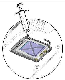
a. Using one syringe of thermal grease (500 mg [0.2 ml]), carefully apply grease to the top of the CPU in an X pattern as shown in FIGURE 3-14.
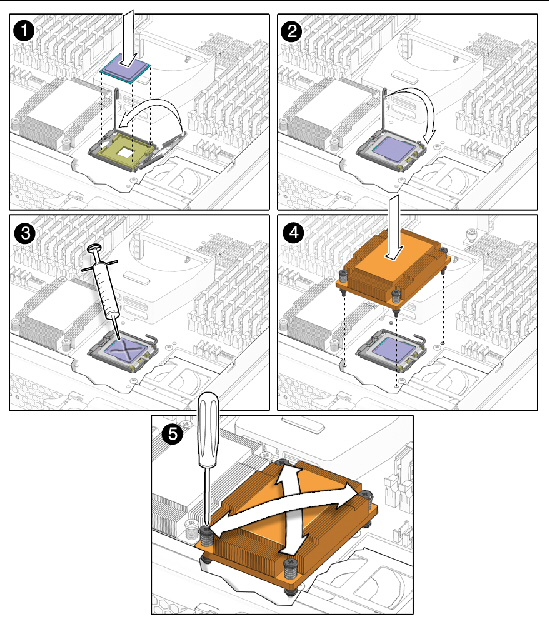
FIGURE 3-14 Applying Thermal Grease
b. If you are reinstalling an existing heatsink, use an alcohol pad to clean all the old thermal grease from the component surface. Also, clean the dust from the heatsink fins.
c. Turn the heatsink upright and reinsert the four springs and mounting screws.

|
Caution - Avoid moving the heatsink after it has contacted the top of the CPU. Too much movement could disturb the layer of thermal grease, leading to component damage. |
d. Carefully position and align the heatsink over the CPU.
e. Lower the heatsink onto the CPU, aligning the mounting screws with their holes on the motherboard.
f. Using an adjustable torque driver, alternately tighten the two heatsink mounting screws, 180 degrees at a time, until each spring is completely compressed. Tighten screws to 8 in-lbs (0.8 Nm).

|
Caution - After replacing the CPU, you must update the BIOS and SP firmware, as described in Updating BIOS, CPLD and the SP. |
The motherboard is always shipped with the enclosure. You should never separate the motherboard from the enclosure.
| Note - This component is an FRU and should be replaced only by qualified service technicians. Contact your Sun Service representative for assistance. |
Supported components and their part numbers are subject to change over time. For the most up-to-date list of replaceable components for these servers, visit:
http://sunsolve.sun.com/handbook_pub/Systems/
1. Click the name and model of your server.
2. On the product page that opens for the server, click on Full Components List for the list of components.
1. Power off the server and remove the server module from the chassis as described in Removing the Server Module From the Chassis.

|
Caution - Do not operate the system with empty slots. Always insert a filler into an empty slot to reduce the possibility of module shutdown. |
2. Remove the main cover as described in Removing the Main Cover.
3. Remove the following components from the motherboard and place them on an antistatic surface.
You must return each HD to the bay from which it was removed. Use an adhesive note or another method to temporarily label the HDs after you remove them.
4. Install the components you removed from the old motherboard onto the new.
You must return each HD to the bay from which it was removed. Use an adhesive note or another method to temporarily label the HDs after you remove them.
The server module includes four HD bays on the front panel.
| Note - HDs are hot-swappable CRUs that can be replaced by anyone. |
The internal system software designation of the HDs is shown in FIGURE 3-15.
Supported components and their part numbers are subject to change over time. For the most up-to-date list of replaceable components for these servers, see:
http://sunsolve.sun.com/handbook_pub/Systems/
1. Click the name and model of your server.
2. On the product page that opens for the server, click on Full Components List for the list of components.
FIGURE 3-15 Designation of Hard Disk Disks

For information about the implementation and configuration of RAID on this server, see the Sun Intel Adaptec BIOS RAID Utility User's Manual.
The X6250 server module supports installing SSDs in the HD bays. Each SSD provides 32Gb of SATA capacity.
The following conditions apply:
Follow these steps to remove and replace a hard disk (HD).
1. Observe the LEDs on the faces of the HDs and identify the defective HD:
| Note - When you replace the HDs, you must return each HD to the bay from which it was removed. Use an adhesive note or another method to temporarily label the HDs when you remove them. |
The server module HDs are hot-swappable, so you can remove an HD either when server module is installed in the chassis or when it is out of the chassis. See FIGURE 3-16.
FIGURE 3-16 Removing the Hard Disk Drive After Removing the Server Module
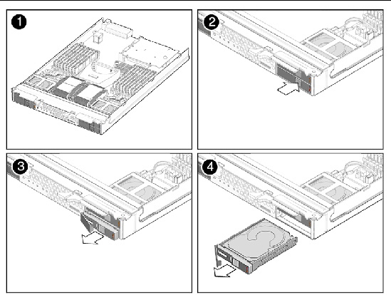
FIGURE 3-17 Removing the Hard Disk Drive Without Removing the Server Module
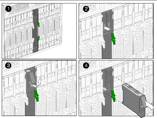
2. Press the button on the face of the HD to release the spring-loaded securing latch. See FIGURE 3-17.
3. Grasp the securing latch and remove the HD from the disk bay.
Installation is the reverse of this procedure.
The Sun Blade RAID 5 Expansion Module (REM) enables RAID functionality.
If you are adding a Sun Blade RAID 5 Expansion Module to a system, you must have a set of SAS HDs to replace the existing SATA HDs. This will effectively remove the operating system, and any data from your system.
When the Sun Blade RAID 5 Expansion Module is installed, SAS disks can be installed in disk slots 0 through 3. These disks can be configured as RAID 0, 1, 1E, 10, 5, or 6 with global or dedicated hot spares, as described in the Sun Intel Adaptec BIOS RAID Utility User's Manual.
To update the REM firmware, see Updating the REM Firmware.
The Sun Blade RAID 5 Expansion Module includes a battery. For instructions, see Changing the Sun Blade RAID 5 Expansion Module Battery.

|
Caution - Backup all data to an external site before adding a REM to server without one. |

|
Caution - If you change a REM on a system with an existing RAID array, to preserve the array configuration and the data in the array, use the procedure in Restoring an Existing RAID Array After Changing the REM. |
1. Ensure that your REM has a battery, and that the cable is connected to the REM.
2. Power off the server and remove the server module from the chassis as described in Removing the Server Module From the Chassis.

|
Caution - Do not operate the system with empty slots. Always insert a filler into an empty slot to reduce the possibility of module shutdown. |
3. Remove the main cover as described in Removing the Main Cover.
4. Remove the existing REM board or the cap from the REM connector if either is present.
The cap should only be present if you are adding a REM board to a server module without one.
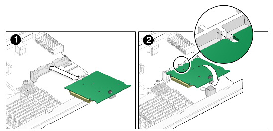
5. Slide the REM board at an angle into the support bracket, then press it carefully into the connector. See FIGURE 3-13.
| Note - For information about the implementation and configuration of RAID on this server, see the Disk Controller Documentation collection. . |
| Note - If you are replacing an existing REM, you are done. If you are adding a REM to a system without a REM, continue. |

|
Caution - The following steps will remove all data from the system. Back up your data to an external site before proceeding. |
6. Remove the hard disks. See Replacing a Hard Disk.
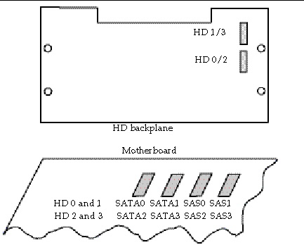
7. To change the disk controller type from SATA to SAS, move the disk control cables on the motherboard.
The server has two HD backplanes positioned behind HD 0 and 1, and behind HD 2 and 3 respectively. Each backplane connector has two cables that connect to the motherboard. The connectors on the HD backplane are labeled HD 1/3 and HD 0/2.
Move the cables on the motherboard as follows:
FIGURE 3-19 shows the HD backplane to motherboard cables.
FIGURE 3-19 HD Backplane Connectors
8. Place the new SAS disks in the disk bays.
Unless you have pre-loaded software on the SAS disks, your server will not have an operating system, or any data. You will need to restore your data from backups, and install the operating system:
When you change the REM on a server module with an existing RAID array, when you restart the server module, the new controller probes the disks, and downloads information about the array. It then offers a selection to restore the existing array.
Use the following procedure to preserve an existing RAID array and the data in it.
|
1. After changing the REM, restart the server module.
The startup messages include a message from the RAID controller utility offering to restore the original array.
2. Accept the option to restore the existing array.
The RAID controller utility restores the existing array.

|
Caution - Declining this option could cause you to lose the array configuration, and the data in the array. |
| Note - Alternatively, if you open the RAID controller utility, it offers a selection to restore the existing array. Accept the option to restore the existing array. |
For information, see the disk controller collection.
The Sun Blade RAID 5 Expansion Module has a battery that should be replaced when indicated in the Sun Intel Adaptec BIOS RAID Utility User's Manual .
If you are adding a Sun Blade RAID 5 Expansion Module to a server module without one, connect the battery to the Sun Blade RAID 5 Expansion Module, as described in Step 5.
| Note - The shipping container might include extra cables. Do not use them. |
1. Power off the server and remove the server module from the chassis as described in Removing the Server Module From the Chassis.

|
Caution - Do not operate the system with empty slots. Always insert a filler into an empty slot to reduce the possibility of module shutdown. |
2. Remove the main cover as described in Removing the Main Cover.
3. Remove the Sun Blade RAID 5 Expansion Module as described in Adding or Replacing a RAID Expansion Module.
a. Turn the Sun Blade RAID 5 Expansion Module board over.
The battery is located underneath the REM board.
b. Disconnect the battery cable from the Sun Blade RAID 5 Expansion Module.
See FIGURE 3-20.
c. Remove the four screws that secure the battery to the Sun Blade RAID 5 Expansion Module board.
d. Lift the battery away from the Sun Blade RAID 5 Expansion Module board.
a. Attach the battery to the Sun Blade RAID 5 Expansion Module using the four screws.
See FIGURE 3-20.
b. Connect the cable on the battery to the connector on the Sun Blade RAID 5 Expansion Module.
| Note - Dispose of the old battery correctly. Do not place it in the trash. |
FIGURE 3-20 REM Battery Screws and Connectors

Figure showing REM batteries, screws, and connectors
The procedures in this section describe how to install and remove an optional Fabric Expansion Module (FEM).
The module is installed on the left side of the center mounting bracket.
1. Power off the server and remove the server module from the chassis as described in Removing the Server Module From the Chassis.

|
Caution - Do not operate the system with empty slots. Always insert a filler into an empty slot to reduce the possibility of module shutdown. |
2. Remove the main cover as described in Removing the Main Cover.
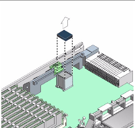
3. Remove the protective cap from the fabric expansion module connector (see FIGURE 3-21).
The fabric expansion module connector is located on the left side of the center support bracket.
FIGURE 3-21 Removing the Connector Cap
4. Position the fabric expansion module (connector side down) over the fabric expansion module connector on the motherboard, and insert the (opposite) edge of the fabric expansion module into the slots on the center support bracket (see FIGURE 3-22).
FIGURE 3-22 Installation of a Fabric Expansion Module
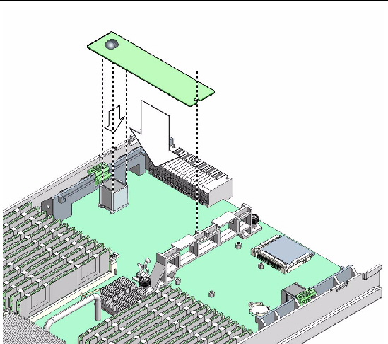
5. Gently press the connector on the underside of the module onto the connector on the motherboard, until the edge of the board is secured by the ejector clip on the left-side support bracket.
1. Power off the server and remove the server module from the chassis as described in Removing the Server Module From the Chassis.

|
Caution - Do not operate the system with empty slots. Always insert a filler into an empty slot to reduce the possibility of module shutdown. |
2. Remove the main cover as described in Removing the Main Cover.
The fabric expansion module connector is located on the left side of the center support bracket.
3. Press down on the ejector lever to unlock the edge of the fabric expansion module.
The ejector lever is located on the left-side support bracket. Unlocking the module allows you to disconnect the module from the motherboard.
4. To disconnect, gently lift the edge of the module off the connector on the motherboard.
The other end of the module is secured under clips on the center support bracket (see FIGURE 3-23).
FIGURE 3-23 Removing a Fabric Expansion Module
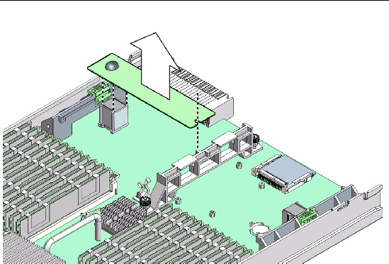
5. When the fabric expansion module is disconnected, pull the card away from the center support bracket, and remove it from the server.
Copyright © 2009 Sun Microsystems, Inc. All rights reserved.