| C H A P T E R 5 |
|
Replacing Field-Replaceable Units |
This chapter describes how to remove and replace customer-replaceable field-replaceable units (FRUs) in the server.
The following topics are covered:
For a list of FRUs, see Appendix A.
|
Note - Never attempt to run the system with the cover removed. The cover must be in place for proper air flow. The cover interlock switch immediately shuts the system down when the cover is removed. |
Use this procedure to remove the optional low-profile PCI-Express (PCI-E) card from the server.
1. Perform the procedures described in Chapter 4.
2. Remove any cables that are attached to the card.
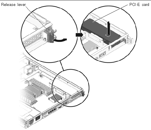
3. On the rear of the chassis, pull the release lever that secures the PCI-Express card to the chassis (FIGURE 5-1).
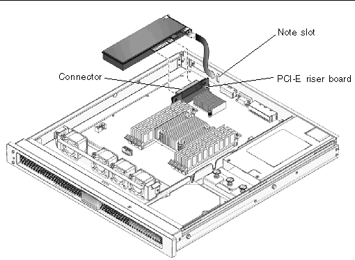
4. Carefully pull the PCI-Express card out of the connector on the PCI-Express card riser board and the note slot (FIGURE 5-2).
5. Place the PCI-Express card on an antistatic mat.
Use this procedure to replace the PCI-Express cards.
1. Unpack the replacement PCI-Express card and place it on an antistatic mat.
2. Insert the PCI-Express card into the connector on the PCI-Express riser board and the note slot (FIGURE 5-2).
3. On the rear of the chassis, engage the release lever to secure the card to the chassis (FIGURE 5-1).
4. Perform the procedures described in Chapter 6.
1. Perform the procedures described in Chapter 4.
2. Disconnect the fan power cable from the motherboard.
3. Push in on the clasps on both sides of the fan assembly (FIGURE 5-3).
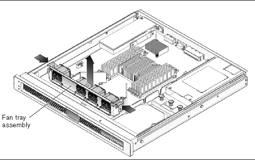
4. Remove the fan assembly from the sheet metal mounting brackets.
1. Unpack the replacement fan tray assembly and place it on an antistatic mat.
2. Align the fan tray assembly with the sheet metal mounting brackets and slide it into place until the clasps on each side lock it into place.
3. Reconnect the fan power cable to the motherboard.
4. Perform the procedures described in Chapter 6.
1. Perform the procedures described in Chapter 4.
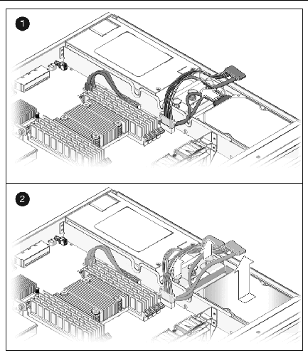
2. Disconnect the power cable from the motherboard and pull the cable through the midwall.
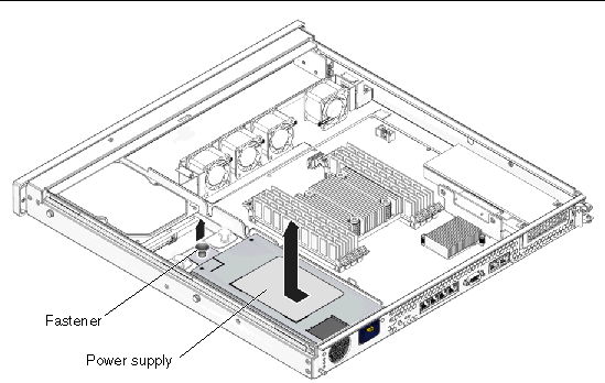
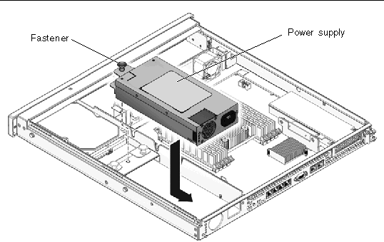
3. Pull the fastener up on the front of the power supply and remove the power supply from the chassis (FIGURE 5-4).
1. Unpack the replacement power supply.
2. Slide the power supply into the chassis and engage the two alignment pins in the rear of the chassis that mate with the power supply.
3. Push the fastener down on the front of the power supply to lock it into place in the chassis (FIGURE 5-5).
4. Redress the power cable through the midwall in the chassis and connect the cable to the motherboard.
5. Perform the procedures described in Chapter 6.
6. At the sc> prompt, issue the showenvironment command to verify the status of the power supply.
1. Disconnect the drive cable from the data/power connector at the rear of the hard drive (FIGURE 5-6).
2. Pull the fasteners up on the rear of the single-drive assembly, and remove the single-drive assembly from the chassis (FIGURE 5-6).
1. Unpack the drive assembly and the dual-drive cable.
The drive assembly should be shipped to you with one or two drives already installed in the assembly, depending on the type of drive assembly that you ordered.
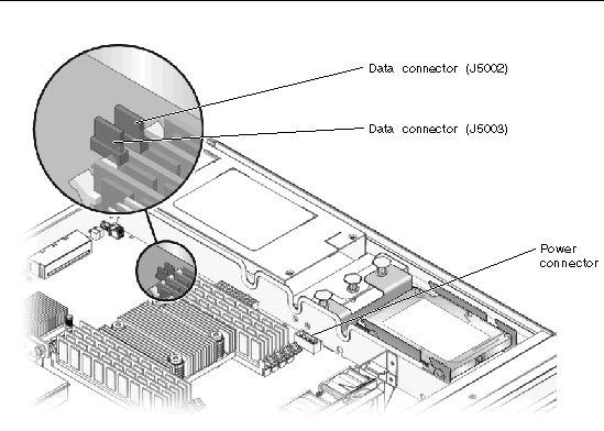
2. Disconnect the drive cable from the data and power connectors on the motherboard and remove the drive cable from your server (FIGURE 5-7).
3. Get the dual-drive cable that was shipped with the new drive assembly.
4. Plug the drive connectors into the data/power connectors at the rear of the hard drives.
5. Slide the drive assembly into the chassis until it mates with the front of the chassis.
FIGURE 5-8 shows a dual-drive assembly being inserted into the chassis. The process is the same for a single-drive assembly.
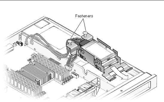
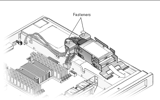
6. Push the fasteners down to lock the drive assembly into place in the chassis (FIGURE 5-8).
7. Redress the cable through the midwall in the chassis.
8. Route the drive data cables underneath the power supply cable.
9. Plug the power connector on the dual-drive cable to the power connector on the motherboard (FIGURE 5-7).
10. Plug the data connector marked J5003 on the cable to the J5003 data connector on the motherboard (the connector furthest from the power supply).
Refer to FIGURE 5-7 for the location of that connector.
11. Plug the data connector marked J5002 on the cable to the J5002 data connector on the motherboard (the connector closest to the power supply).
Refer to FIGURE 5-7 for the location of that connector.
12. Place the top cover on the chassis.
Set the cover down so that the cover hangs over the rear of the server by about an inch (2.5 cm).
13. Slide the cover forward until it latches into place.
14. Reinstall the server in the rack and apply power to the server.
Refer to the Sun SPARC Enterprise T1000 Server Service Manual for those instructions.
15. Label the hard drives, if necessary.
16. Upgrade the drive controller firmware, if necessary.
If you have an older version of the drive controller firmware, then you must upgrade the drive controller firmware to get full support for mirroring and other RAID features.
a. Determine the version of the drive controller firmware installed on your server by entering the following command:
You should see output similar to the following:
Jun 7 13:23:16 wgs57-57 genunix: [ID 540533 kern.notice] SunOS Release 5.10 Version Generic_118833-08 64-bit Jun 7 13:23:16 wgs57-57 mpt0 Firmware version v1.a.0.0 (IR) |
then you have the latest drive controller firmware. Go to Step 17.
Once the patch has been installed, your system will have the latest drive controller firmware.
17. Perform the necessary administrative tasks to reconfigure the hard drive.
The procedures that you perform at this point depend on how your data is configured. You might need to partition the drive, create file systems, load data from backups, or have the data updated from a RAID configuration.
1. Perform the procedures described in Chapter 4.
2. Disconnect the drive cable from the data/power connector at the rear of the hard drive (FIGURE 5-9).
3. Pull the fasteners up on the rear of the single-drive assembly and remove the assembly from the chassis (FIGURE 5-9).
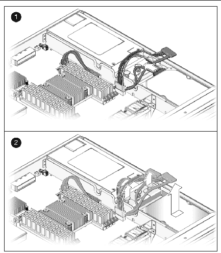
1. Unpack the replacement single-drive assembly.
2. Slide the single-drive assembly into the chassis until it mates with the front of the chassis (FIGURE 5-10).
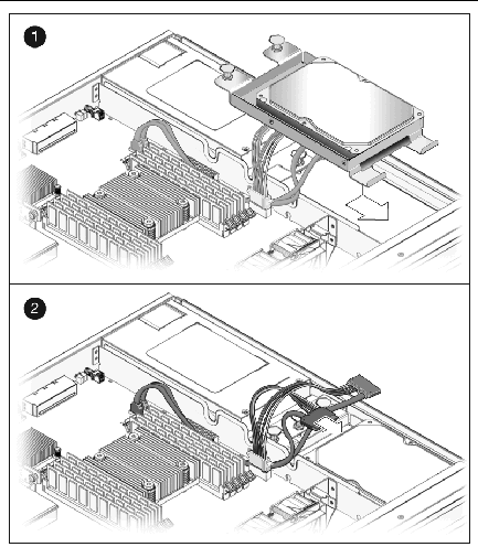
3. Push the fasteners down to lock the drive assembly into place in the chassis.
4. Redress the cable through the midwall in the chassis.
5. Reconnect the data cable to the data/power connector on the drive (FIGURE 5-10).
If you have a dual-drive cable installed in your system, connect the DRIVE 0 connector on the cable to the data/power connector at the rear of the drive. Do not connect the DRIVE 1 connector on the cable to the data/power connector at the rear of the drive in a single-drive assembly.
6. Perform the procedures described in Chapter 6.
7. Perform the necessary administrative tasks to reconfigure the hard drive.
The procedures that you perform at this point depend on how your data is configured. You might need to partition the drive, create file systems, or load data from backups.
1. Perform the procedures described in Chapter 4.
2. Disconnect the drive cable from the data and power connectors on the motherboard (FIGURE 5-11).
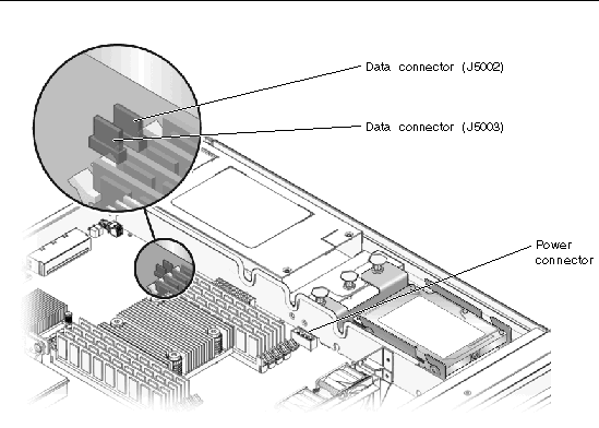
3. Pull the fasteners up on the rear of the dual-drive assembly and remove the dual-drive assembly from the chassis (FIGURE 5-12).
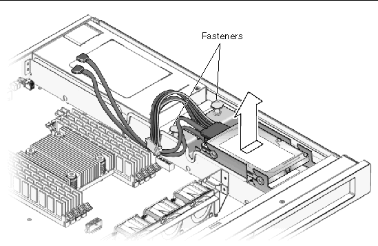
4. Determine which of the two hard drives you want to remove.
5. Remove the drive from the drive bracket.
If you are removing the lower drive, you must first remove the upper drive before you can remove the lower drive.
a. Disconnect the drive cable from the data/power connector on the upper drive.
b. Push the drive toward the back of the drive bracket and lift the drive away from the bracket.
a. Disconnect the drive cable from the data/power connector on the lower drive.
b. Push the drive toward the back of the drive bracket and lift the drive away from the bracket.
1. Unpack the replacement hard drive.
2. Install the replacement drive in the drive bracket.
a. Install the replacement drive in the lower drive slot in the drive bracket.
b. Push the drive firmly toward the front of the drive bracket until the hard drive is completely seated.
c. Plug the DRIVE 0 connector on the drive cable into the data/power connector on the lower drive.
Make sure the connector is correctly oriented before plugging it into the data/power connector on the drive.
a. Install the replacement drive in the upper drive slot in the drive bracket.
b. Push the drive firmly toward the front of the drive bracket until the hard drive is completely seated.
c. Plug the DRIVE 1 connector on the drive cable into the data/power connector on the upper drive.
Ensure that the connector is correctly oriented before plugging it into the data/power connector on the drive.
3. Slide the drive assembly into the chassis until it mates with the front of the chassis (FIGURE 5-13).
4. Push the fasteners down to lock the drive assembly into place in the chassis (FIGURE 5-13).
5. Redress the cable through the midwall in the chassis.
6. Route the drive data cables underneath the power supply cable.
7. Plug the power connector on the dual-drive cable to the power connector on the motherboard (FIGURE 5-11).
8. Plug the data connector marked J5003 on the cable to the J5003 data connector on the motherboard (the connector farthest from the power supply).
Refer to FIGURE 5-11 for the location of the J5003 data connector.
9. Plug the data connector marked J5002 on the cable to the J5002 data connector on the motherboard (the connector closest to the power supply).
Refer to FIGURE 5-11 for the location of the J5002 data connector.
10. Perform the procedures described in Chapter 6.
11. Use the Solaris format utility to label the 2.5-inch SAS hard drives.
Refer to the Labeling Unlabeled Hard Drives document for those instructions.
12. Perform the necessary administrative tasks to reconfigure the hard drive.
The procedures that you perform at this point depend on how your data is configured. You might need to partition the drive, create file systems, load data from backups, or have the data updated from a RAID configuration.
|
Note - Not all DIMMs detected as faulty and offlined by POST must be replaced. In service (maximum) mode, POST detects memory devices with errors that might be corrected with Solaris PSH. See Section 3.4.5, Correctable Errors Detected by POST. |

|
Caution - This procedure requires that you handle components that are sensitive to static discharges that can cause the component to fail. To avoid this problem, follow the antistatic practices as described in Chapter 4. |
1. Perform the procedures described in Chapter 4.
2. Locate the DIMM that you want to remove.
Use FIGURE 5-14 and TABLE 5-1 to identify the DIMM that you want to remove.
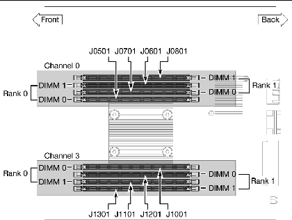
TABLE 5-1 maps the DIMM names that are displayed in faults to the socket numbers that identify the location of the DIMM on the motherboard. The Channel/Rank/DIMM locations (for example, CH0/R0/D0) are silkscreened on the board and on a label near the board.
3. Note the DIMM location so that you can install the replacement DIMM in the same socket.
4. Push down on the ejector levers on each side of the DIMM until the DIMM is released.
5. Grasp the top corners of the DIMM and remove it from the motherboard.
6. Place the DIMM on an antistatic mat.
Use the following guidelines and FIGURE 5-14 and TABLE 5-1 to plan the memory configuration of your server.
1. Unpack the replacement DIMMs and place them on an antistatic mat.
2. Ensure that the socket ejector tabs are in the open position.
3. Line up the replacement DIMM with the connector.
4. Push the DIMM into the socket until the ejector tabs lock the DIMM in place.
5. Perform the procedures described in Chapter 6.
|
Note - You must replace the top cover as instructed in the Chapter 6 chapter before proceeding with these instructions. The top cover must be in place for ALOM CMT to detect that a DIMM has been replaced. |
6. Gain access to the ALOM sc> prompt.
Refer to the Advanced Lights Out Management (ALOM) CMT Guide for instructions.
7. Run the showfaults -v command to determine how to clear the fault.
The method you use to clear a fault depends on how the fault is identified by the showfaults command.
then run the enablecomponent command to enable the FRU:
8. Perform the following steps to verify the repair:
a. Set the virtual keyswitch to diag so that POST will run in Service mode.
c. Switch to the system console to view the POST output.
Watch the POST output for possible fault messages. The following output is a sign that POST did not detect any faults:
d. Return the virtual keyswitch to normal mode.
e. Issue the Solaris OS fmadm faulty command.
No memory or DIMM faults should be displayed.
If faults are reported, refer to the diagnostics flow chart in FIGURE 3-1 for an approach to diagnose the fault.
9. Obtain the ALOM CMT sc> prompt.
10. Run the showfaults command.
If the fault was detected by the host and the fault information persists, the output will be similar to the following example:
sc> showfaults -v ID Time FRU Fault 0 SEP 09 11:09:26 MB/CMP0/CH0/R0/D0 Host detected fault MSGID: SUN4V-8000-DX UUID: f92e9fbe-735e-c218-cf87-9e1720a28004 |
If the showfaults command does not report a fault with a UUID, then you do not need to proceed with the following steps because the fault is cleared.
11. Run the clearfault command.
12. Switch to the system console.
13. Issue the fmadm repair command with the UUID.
Use the same UUID that you used with the clearfault command.
The motherboard and chassis are replaced as a unit. Therefore, you must remove all FRUs and associated cables from your chassis, and install them in the new chassis.
1. Perform the procedures described in Chapter 4.
2. Remove the PCI-Express card.
See Section 5.1, Replacing the Optional PCI-Express Card.
3. Remove the fan tray assembly and cable.
See Section 5.2, Replacing the Fan Tray Assembly.
4. Remove the power supply and cable.
See Section 5.3, Replacing the Power Supply.
5. Remove the hard drive and cable.
See Section 5.5, Replacing a Hard Drive.
6. Remove all DIMMs from the motherboard assembly.
See Section 5.6, Replacing DIMMs.
7. Remove the socketed system configuration SEEPROM from the motherboard and place it on an antistatic mat.
The system configuration SEEPROM contains the persistent storage for the host ID and Ethernet MAC addresses of the system, as well as the ALOM configuration including the IP addresses and ALOM user accounts, if configured. This information will be lost unless the system configuration SEEPROM is removed and installed in the replacement motherboard. The PROM does not hold the fault data, and this data is no longer accessible once the motherboard and chassis assembly is replaced.
The location of this SEEPROM is shown in Appendix A.
1. Replace the PCI-Express card.
See Section 5.1, Replacing the Optional PCI-Express Card.
2. Replace the fan tray assembly and cable.
See Section 5.2, Replacing the Fan Tray Assembly.
3. Replace the power supply and cable.
See Section 5.3, Replacing the Power Supply.
4. Replace the hard drive and cable.
See Section 5.5, Replacing a Hard Drive.
See Section 5.6, Replacing DIMMs.
6. Replace the socketed system configuration SEEPROM.
The location of this SEEPROM is shown in Appendix A.
7. Perform the procedures described in Chapter 6.
8. Boot the system and run POST to verify that the system is fully operational.
See Section 3.4, Running POST.
1. Perform the procedures described in Chapter 4.
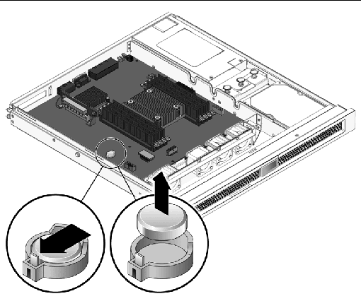
2. Using a small flathead screwdriver, carefully pry the battery from the motherboard (FIGURE 5-15).
1. Unpack the replacement battery.
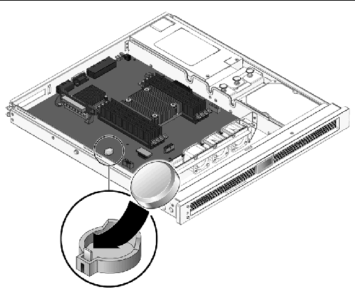
2. Press the new battery into the motherboard with the + facing upward (FIGURE 5-16).
3. Perform the procedures described in Chapter 6.
4. Use the ALOM setdate command to set the day and time.
Use the setdate command before you power on the host system. For details about this command, refer to the Advanced Lights Out Management (ALOM) CMT Guide.
Copyright © 2007, Sun Microsystems, Inc. All Rights Reserved.