Sun Netra X4450 Server
Service Manual X4450 Server
Service Manual |
| C H A P T E R 2 |
This chapter describes safety considerations and provides prerequisite procedures and information to replace components within the server.
This section describes important safety information you need to know prior to removing or installing parts in the server.
For your protection, observe the following safety precautions when setting up your equipment:
Follow all Sun standard cautions, warnings, and instructions marked on the equipment and described in Important Safety Information for Sun Hardware Systems, 816-7190.
Ensure that the voltage and frequency of your power source match the voltage and frequency inscribed on the equipment s electrical rating label.
Follow the electrostatic discharge safety practices as described in this section.
The following symbols might appear in this book, note their meanings:
 | Caution - There is a risk of personal injury and equipment damage. To avoid personal injury and equipment damage, follow the instructions. |
 | Caution - Hot surface. Avoid contact. Surfaces are hot and might cause personal injury if touched. |
 | Caution - Hazardous voltages are present. To reduce the risk of electric shock and danger to personal health, follow the instructions. |
Electrostatic discharge (ESD) sensitive devices, such as the motherboard, PCI cards, hard drives, and memory cards require special handling.
Wear an antistatic wrist strap and use an antistatic mat when handling components such as drive assemblies, boards, or cards. When servicing or removing server components, attach an antistatic strap to your wrist and then to a metal area on the chassis. Then disconnect the power cords from the server. Following this practice equalizes the electrical potentials between you and the server.
Before you can remove and install components that are inside the server, you must prepare the server for service.
Note - When replacing the hard drives or power supplies, not all of these tasks are necessary. The replacement procedures for those components address this fact. |
Performing a graceful shutdown makes sure all of your data is saved and the system is ready for restart.
Log in as superuser or equivalent.
Depending on the nature of the problem, you might want to view the system status, the log files, or run diagnostics before you shut down the system. Refer to the administration documentation for log file information.
Refer to your administration documentation for additional information.
Save any open files, and quit all running programs.
Refer to your application documentation for specific information on these processes.
Shut down the operating system.
Refer to the operating system documentation for additional information.
You can shut down the server from the CLI, or you can use the Power button on the front of the server to initiate a graceful system shutdown. This button is recessed to prevent accidental server power-off. Use the tip of a pen to operate this button.
 | Caution - The system supplies standby power to the circuit boards even when the system is powered off. |
Remove the server from the rack prior to performing cold-swappable replacement procedures.
 | Caution - The server weighs approximately 64 lbs (32 kg). Two people are required to dismount and carry the chassis. |
Remove the server from the rack.
The steps to remove the server from the rack depend on the mounting kit. For sliding mounting kits, you can simply release the slides to remove the server. For hardmount kits, you must remove the securing screws from the front and rear brackets.
Prepare an antistatic surface on which to set parts during removal and installation.
Place ESD-sensitive components such as the printed circuit boards on an antistatic mat. The following items can be used as an antistatic mat:
Attach an antistatic wrist strap.
When servicing or removing server components, attach an antistatic strap to your wrist and then to a metal area on the chassis.
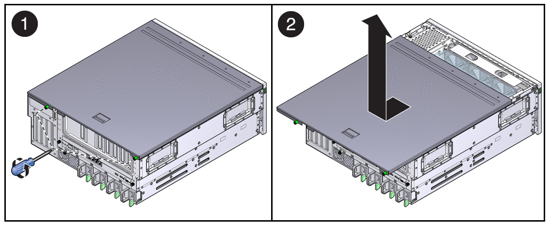
Use a No. 2 Philips screwdriver to release the two captive screws (FIGURE 2-1).

While pressing the top cover release button, slide the cover toward the rear of the server.
The removal of the memory mezzanine is necessary only if you are servicing the following components:
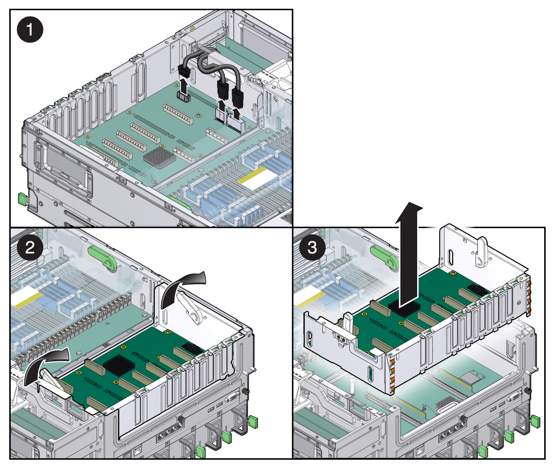
Disconnect the three system cables that are connected to the PCI mezzanine board (FIGURE 2-4).

Lift the PCI mezzanine up and out the chassis, and place it on an antistatic mat.
 | Caution - One or more of the PCI riser cards beneath the PCI mezzanine might remain attached to the bottom of the mezzanine. Therefore, be careful when you remove the mezzanine. |
Copyright © 2008, Sun Microsystems, Inc. All rights reserved.