Sun Netra X4450 Server
Service Manual X4450 Server
Service Manual |
| C H A P T E R 3 |
This chapter provides instructions for replacing the server components.
The following topics are included:
Use the procedures in this section to install a new air filter or to remove the air filter for cleaning.
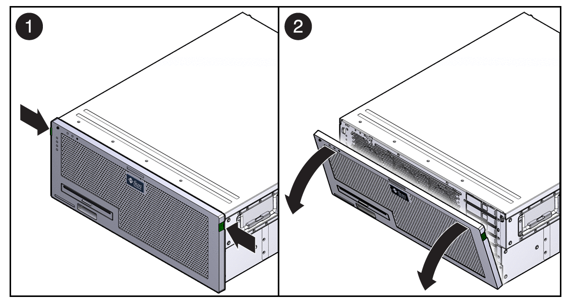
Press the green tabs on both sides of the bezel, and pull the bezel forward and down (FIGURE 3-2).
 | Caution - Do not open the bezel on a flat surface. The front of the server must be hanging over the edge of a flat surface to avoid damaging the bezel hinges. |
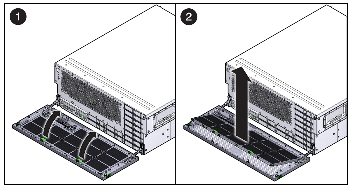
Grasp the tabs, and lift the air filter from the bezel (FIGURE 3-2).
The server’s redundant hot-swappable power supplies enable you to remove and replace one or two power supplies without shutting the server down, provided that the other power supplies are online and working.
If a power supply fails and you do not have a replacement available, leave the failed power supply installed to ensure proper air flow in the server.
Identify which power supply requires replacement.
A lighted amber indicator on a power supply indicates that a failure was detected.
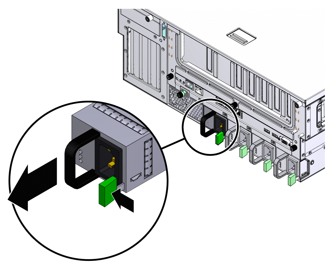
Grasp the power supply handle, and push the power supply latch to the right (FIGURE 3-4).
Remove the replacement power supply from its packaging, and place the power supply on an antistatic mat.
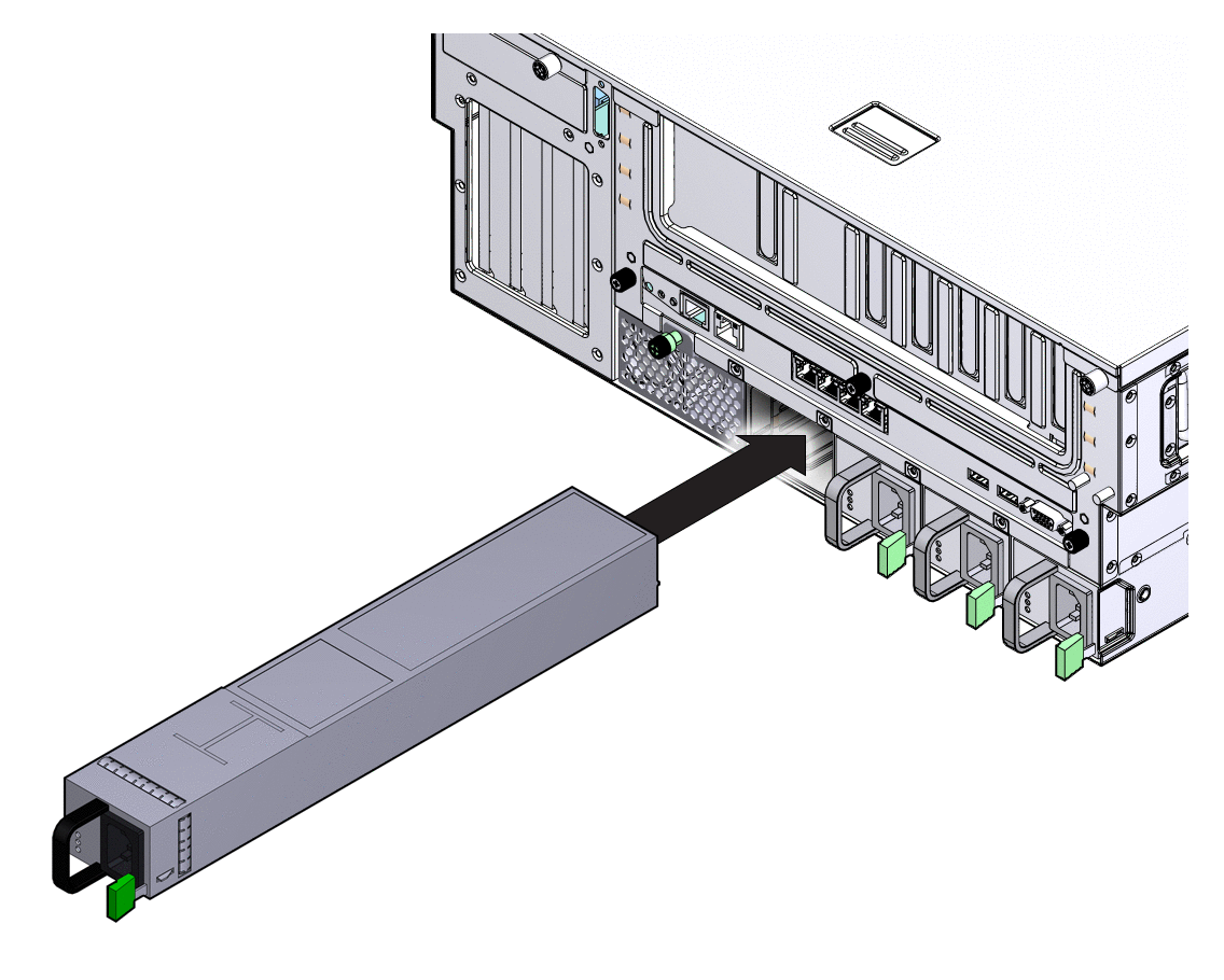
Slide the power supply into bay until it is fully seated (FIGURE 3-5).
Verify that the amber indicator on the replaced power supply and that the Service Required Indicators are not lit.
The hard drives in the server are hot-pluggable, but this capability depends on how the hard drives are configured. To hot-plug a drive, you must be able to take the drive offline by preventing any applications from accessing the drive and removing the logical software links to the drive.
The following situations inhibit the ability to perform hot-plugging of a drive:
The hard drive provides the operating system, and the operating system is not mirrored on another drive.
The hard drive cannot be logically isolated from the online operations of the server.
If your drive falls into one of these conditions, you must shut the system down before you replace the hard drive.
Note - Replacing a hard drive does not require removing the server from a rack. |
If the drive you want to remove cannot be hot-plugged, perform the tasks in Chapter 2 before you perform the steps in this procedure.
Open the bezel (FIGURE 3-6).
 | Caution - Do not open the bezel on a flat surface. The front of the server must be hanging over the edge of a flat surface to avoid damaging the bezel hinges. |

Type the Solaris OS commands required to stop using the hard drive.
Exact commands required depend on the configuration of your hard drives. You might need to unmount file systems or perform RAID commands.
On the drive you plan to remove, push the latch release button (FIGURE 3-7).
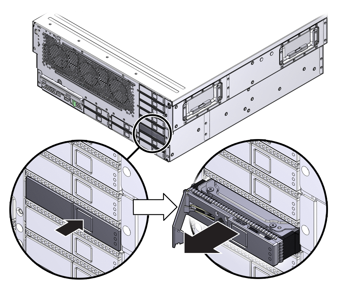
 | Caution - The latch is not an ejector. Do not bend it too far to the left. Doing so can damage the latch. |
Remove the replacement hard drive from its packaging, and place it on an antistatic mat.
Align the replacement drive to the drive slot.
The hard drive is physically addressed according to the slot in which it is installed. It is important to install a replacement drive in the same slot as the drive that was removed.
Slide the drive into the bay until it is fully seated (FIGURE 3-8).
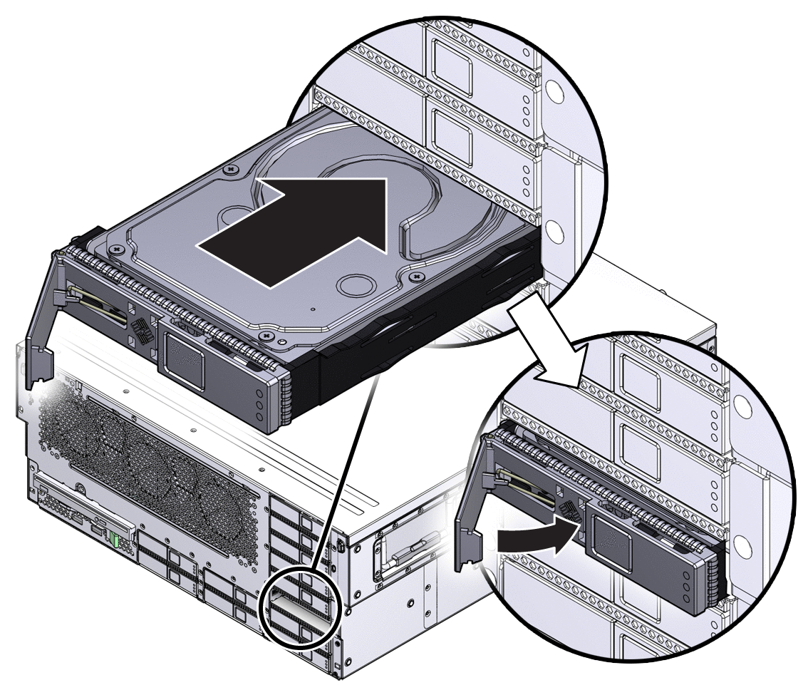
Perform administrative tasks to reconfigure the hard drive.
The procedures that you perform at this point depend on how your data is configured. You might need to partition the drive, create file systems, load data from backups, or have it updated from a RAID configuration.
The optical media drive in the server is not hot-pluggable. You cannot remove it while the system is running.
Prepare the server for optical media drive removal.
See Chapter 2.
 | Caution - Do not open the bezel on a flat surface. The front of the server must be hanging over the edge of a flat surface to avoid damaging the bezel hinges. |
Push the release tab to the left, and pull the probe forward, freeing the optical media drive (FIGURE 3-9).
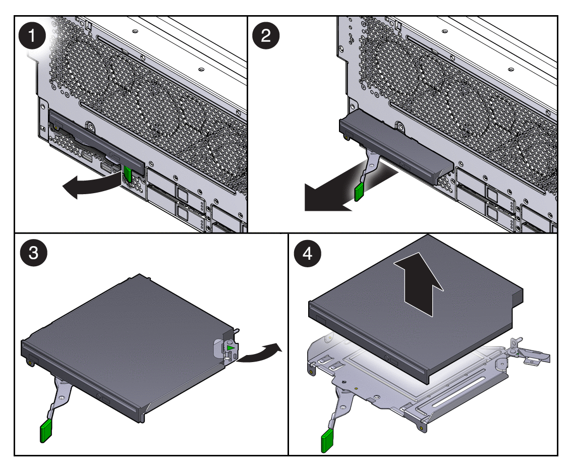
Remove the optical media drive from server, and set it aside on an antistatic mat.
Remove the replacement optical media drive from its packaging, and place it on an antistatic mat.
Hold the tab to the left, and insert the optical media drive into the chassis (FIGURE 3-10).
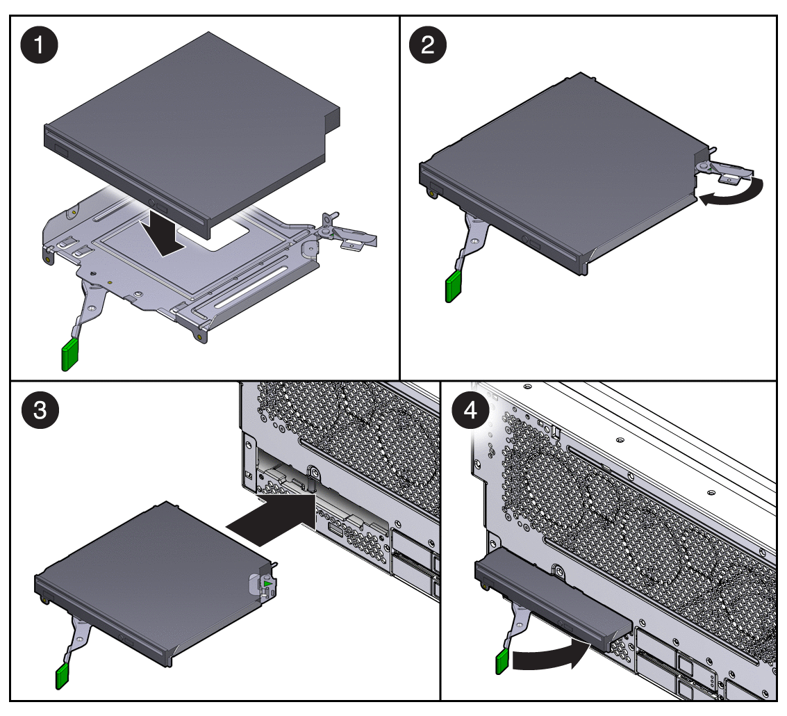
Press the optical media drive in until it seats, and release the tab.
If you installed the optical media drive as part of another procedure, return to that procedure.
Otherwise, perform the tasks needed to bring the server back online.
See Chapter 4.
Use the FB-DIMM configuration rules to help you plan the memory configuration of your server. There are 32 slots that hold industry-standard FB-DIMM memory modules. General rules are:
FB-DIMMs must be installed in identical pairs (that is, the same size, speed, and organization).
A replacement FB-DIMM must have the same part number as the other FB-DIMM in its pair. If you are unable to obtain a matching FB-DIMM, you must replace both FB‐DIMMs in the pair.
FB-DIMM pairs must be installed in the following slot order: A0/B0, C0/D0, A1/B1, then C1/D1.
FB-DIMM capacities can be different between slots. For example, you can install a pair of 2-GB FB-DIMMs in slots A0 or B0 and a pair of 1-GB FB-DIMMs in slots C0 or D0.
Highest capacity FB-DIMMs must be installed in the lowest numbered slots. For instance, if you have four 4-GB FB-DIMMs and four 2-GB FB-DIMMs, you must install the 4-GB FB-DIMMs in slots A0/B0 and C0/D0, and you must install the 2-GB FB-DIMMs in slots A1/B1 and C1/D1.
 | Caution - Ensure that all power is removed from the server before removing or installing FB-DIMMs. You must disconnect the power cables before performing this procedure. |
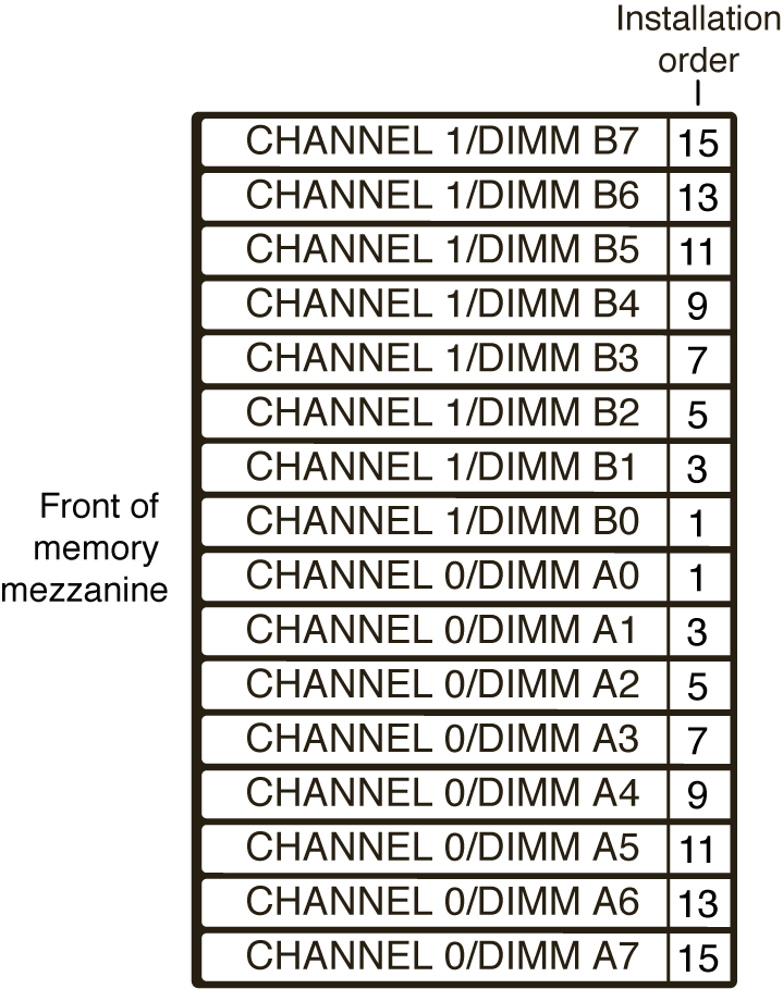
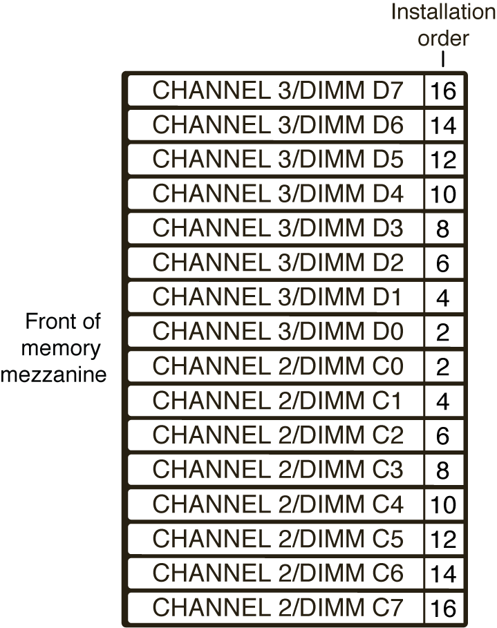
Note - FB-DIMM names in ILOM messages are displayed with the full FRU name, such as /SYS/MB/CMP0/BR0/CH0/D0. |
 | Caution - Always perform antistatic measures by using a wrist strap and an antistatic mat for handling and storing removable components. |
The system Service Required Indicator lights if the system detects a FB-DIMM fault. See Memory Fault Handling.
Prepare the server for FB-DIMM removal.
See Chapter 2.
Press the FB-DIMM fault locator button.
The button is located on the left edge of the memory mezzanine.
Note the location of faulty FB-DIMMs.
Faulty FB-DIMMs are identified with a corresponding amber indicator.
Note - The FB-DIMM fault indicator remains lit only for a few minutes. |
Ensure that all FB-DIMMs are seated correctly in their slots.
If you have not already done so, prepare the server for FB-DIMM removal.
See Chapter 2.
Push down on the ejector tabs on each side of the FB-DIMM until the FB‐DIMM is released (FIGURE 3-13).
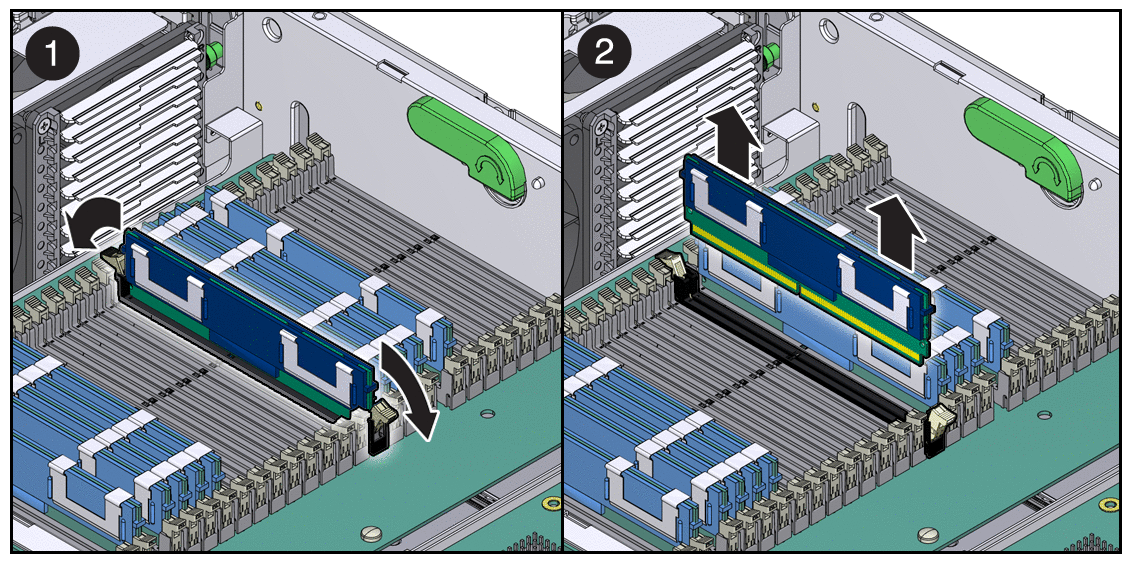
Grasp the top corners of the faulty FB-DIMM, and remove it from the memory mezzanine.
Repeat Step 2 through Step 4 to remove any additional FB-DIMMs.
If you are adding memory, prepare the server for service.
See Chapter 2.
Unpackage the FB-DIMMs, and place them on an antistatic mat.
Line up the replacement FB-DIMM with the connector (FIGURE 3-14).
Align the FB-DIMM notch with the key in the connector. This ensures that the FB-DIMM is oriented correctly.
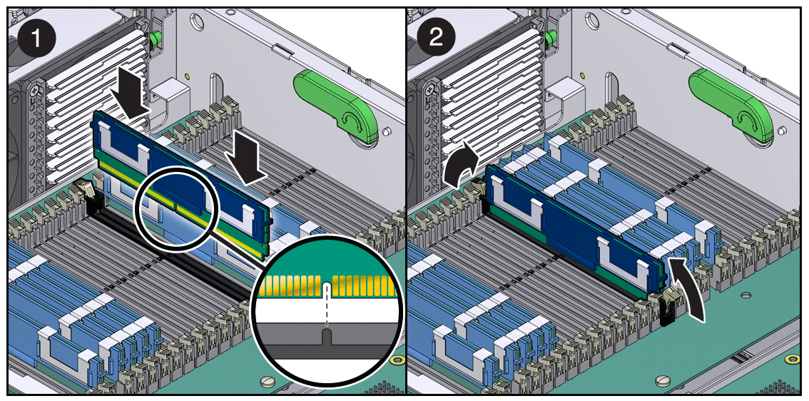
Push the FB-DIMM into the connector until the ejector tabs lock the FB-DIMM in place.
If the FB-DIMM does not easily seat into the connector, verify that the orientation of the FB-DIMM is as shown in FIGURE 3-14. If the orientation is reversed, damage to the FB-DIMM might occur.
Repeat Step 3 through Step 5 until all replacement FB-DIMMs are installed.
If you installed FB-DIMMs as part of another procedure, return to that procedure.
If you are only installing FB-DIMMs, see Chapter 4 for the tasks needed to bring the server back online.
System fan 0 is labeled FT0 and is located at the front of the chassis.
Prepare the server for fan assembly removal.
See Chapter 2.
Insert your forefinger and thumb into the holes at the top of the fan assembly, squeeze them together, and lift the fan assembly from the chassis (FIGURE 3-15).
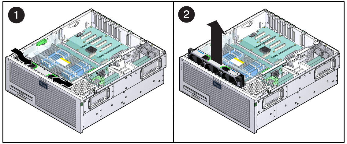
If you removed the fan assembly as part of another procedure, return to that procedure.
Otherwise, continue to Install System Fan 0.
Remove the replacement fan assembly from its packaging, and place it on an antistatic mat.
Insert your forefinger and thumb into the holes at the top of the fan assembly, squeeze them together, and lower the fan assembly into the chassis (FIGURE 3-16).
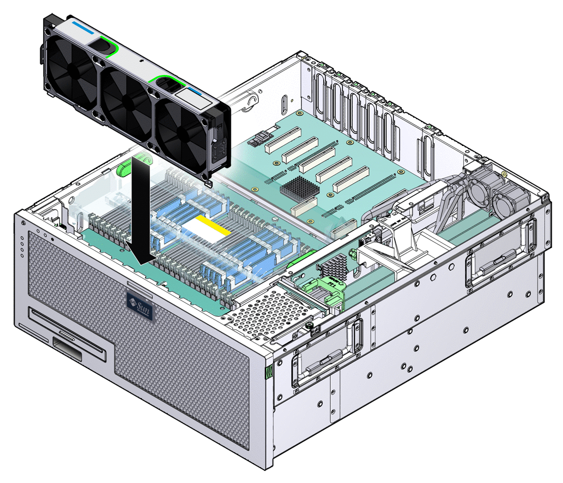
If you installed the fan assembly as part of another procedure, return to that procedure.
Otherwise, see Chapter 4 to perform the tasks needed to bring the server back online.
System fan 1 is labeled FT1 and is located directly behind the hard drive stack.
Prepare the server for fan removal.
See Chapter 2.
Slide the bracket forward, and lift the fan assembly out (FIGURE 3-17).
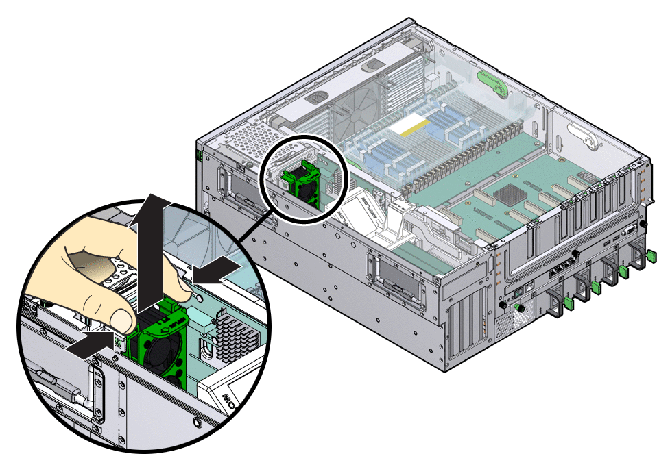
Continue to Install System Fan 1.
Remove the replacement fan assembly from its packaging, and place it on an antistatic mat.
Lower the fan assembly into the chassis, and press it down until the brackets seat properly (FIGURE 3-18).
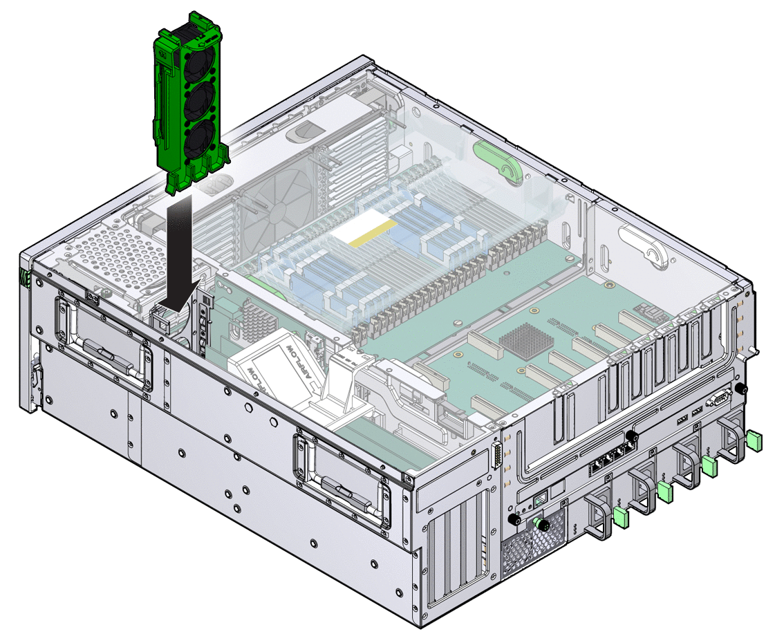
See Chapter 4 to perform the tasks needed to bring the server back online.
System fan 2 is labeled FT2 and is located at the rear of the chassis.
Prepare the server for fan removal.
See Chapter 2
Untighten the captive screw on the fan assembly housing, and pull the housing out of the chassis (FIGURE 3-18).
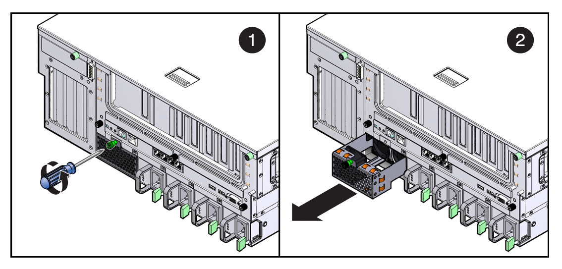
Continue to Replacing System Fan 1.
Remove the replacement fan assembly from its packaging, and place it on an antistatic mat.
Slide the fan assembly housing into the chassis until it is fully seated.
See Chapter 4 to perform the tasks needed to bring the server back online.
The PCI mezzanine secures the PCI cards into place with green PCI card retainers and captive (nonremovable) securing screws.
Note - The maximum power of any one PCI card is 25 watts. Only slots 0-3 accept long cards. |
Prepare the server for PCI card removal.
See Chapter 2.
Remove the PCI air baffle (FIGURE 3-21).
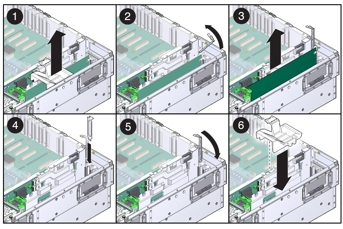
If you are replacing the card, continue to Install PCI-X and PCIe Cards in Slot 0-3.
See Chapter 4 to perform the tasks needed to bring the server back online.
Prepare the server for PCI card installation.
See Chapter 2.
Remove the replacement card from its packaging and place it onto an antistatic mat.
Remove the PCI air baffle (FIGURE 3-21).
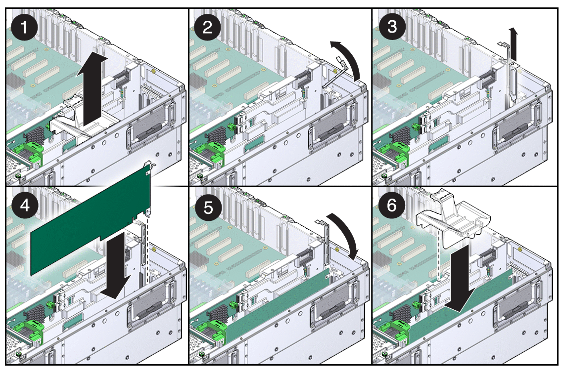
If a filler panel is installed, remove it by pulling the tab.
See Chapter 4 to perform the tasks needed to bring the server back online.
Note - In a fully loaded system, the maximum power of any one PCI card is 25 watts. |
With the PCI mezzanine installed and cabled, identify which card is to be removed.
Loosen the appropriate PCI card retainer (FIGURE 3-22).
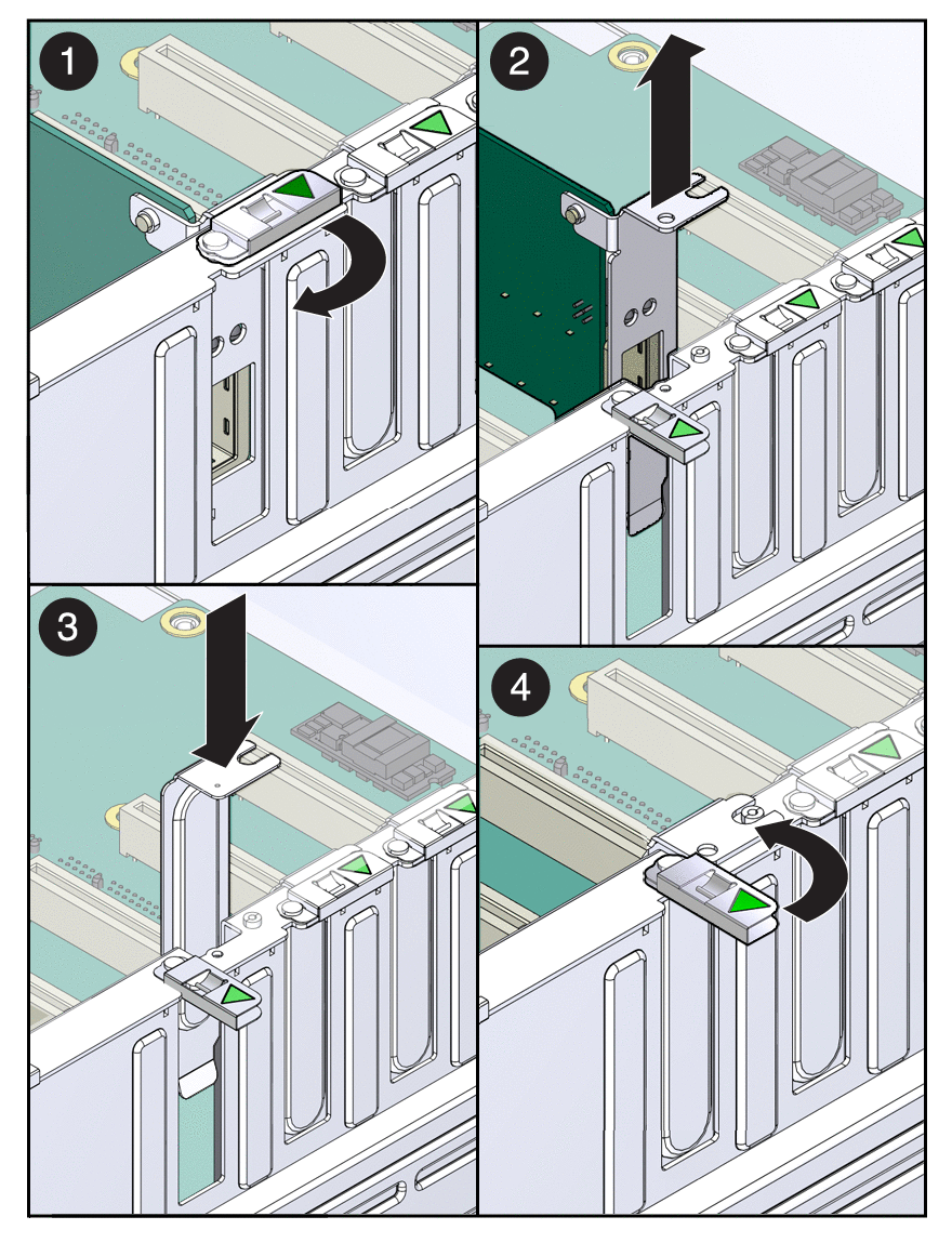
Slide the card to the left and lift it out of the PCI mezzanine.
If you are replacing the card, continue to Install PCI Cards in the PCI Mezzanine.
See Chapter 4 to perform the tasks needed to bring the server back online.
Prepare the server for PCI card installation.
See Chapter 2.
Remove the replacement card from its packaging and place it onto an antistatic mat.
If a filler panel is installed, remove it by pulling the tab.
Lower the card into position on the PCI mezzanine, then slide it to the right to seat it into the connector.
See Chapter 4 to perform the tasks needed to bring the server back online.
To replace the system/alarm LED board, you must remove the following components:
Air baffle (see Remove the Air Baffle)
Memory mezzanine (see Remove the Memory Mezzanine
System fan 0 (see Replacing System Fan 0)
Prepare the server for system/alarm LED board removal.
See Chapter 2.
Loosen the thumbscrew of the LED board, and swing the board out to the left (FIGURE 3-23).
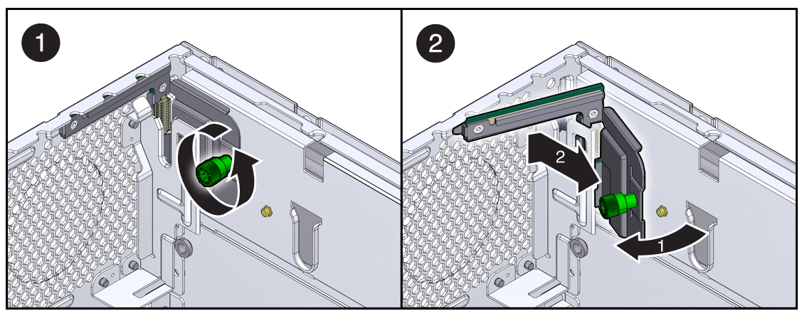
Continue to Install the System/Alarm LED Board.
Remove the replacement LED board from its packaging and place it on an antistatic mat.
Insert the tab on the LED board into the slot on the chassis.
Swing the LED board right to the chassis and tighten the thumbscrew.
See Chapter 4 to perform the tasks needed to bring the server back online.
Use the instructions in this section to replace the SAS expander card.
Prepare the server for removal of the SAS expander card.
See Chapter 2.
Loosen the green captive screw on the expander card (FIGURE 3-24).
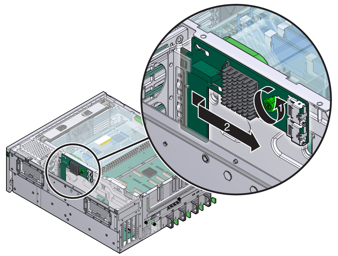
Slide the expander card straight back until the keyhole slots on the front of the card clear the expansion card posts.
Pull the expander card away from the chassis wall until it is clear of the expander posts.
Align the keyhole slots on the expander card with the posts on the chassis wall.
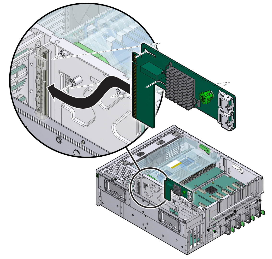
Push the expander card against the chassis wall, then push the card forward until the card is seated into the interconnect slot.
Tighten the green captive screw, and attach the two expansion cables.
See Chapter 4 for instructions on how to return the server to service.
Before you replace the battery, you must remove the following components as part of preparing the server for battery removal:
Air baffle (see Remove the Air Baffle)
PCI mezzanine (see Remove the PCI Mezzanine)
Prepare the server for battery removal.
See Chapter 2.
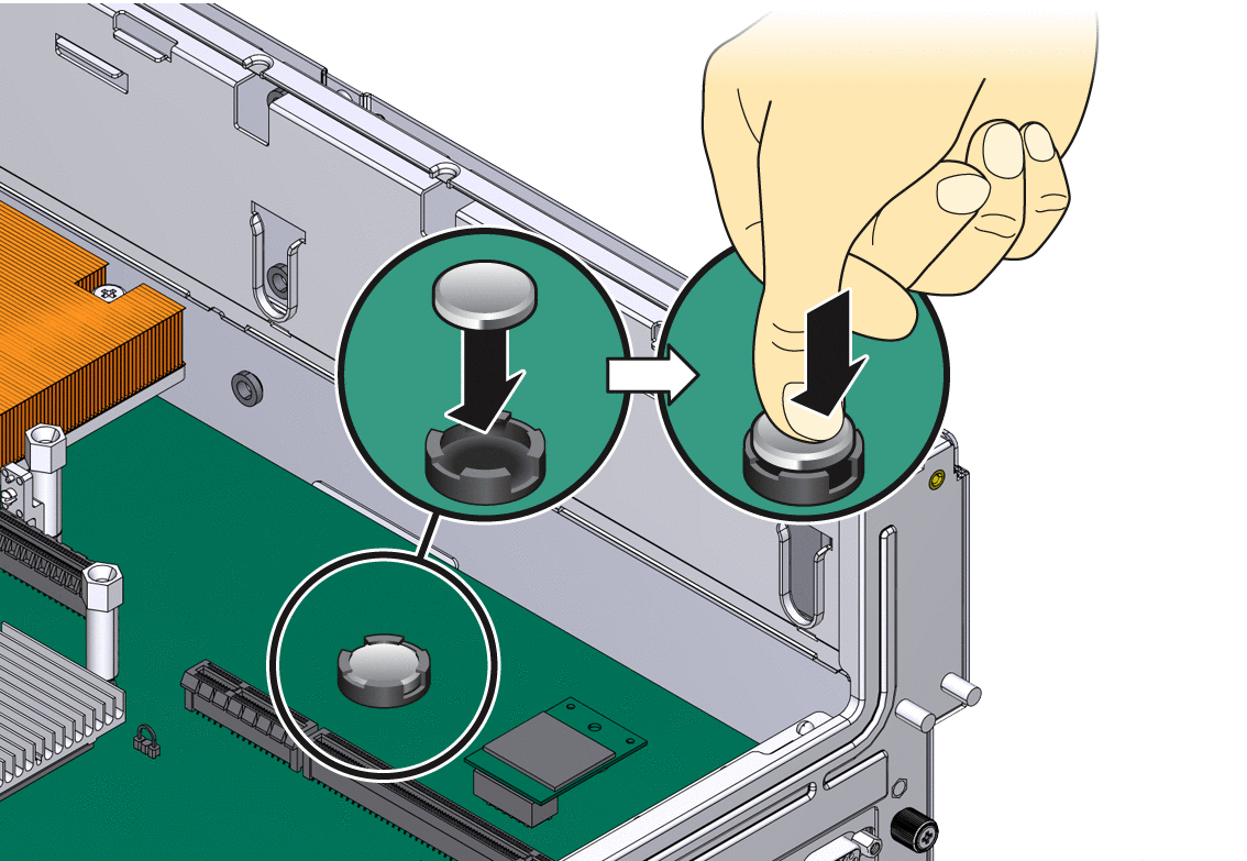
Pry the battery out of the motherboard (FIGURE 3-26).
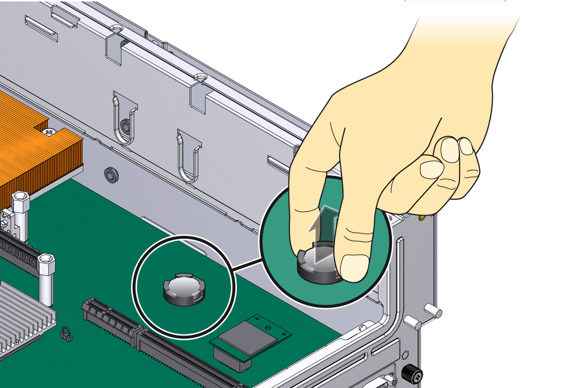
Press the new battery in with the “+” side facing up (FIGURE 3-27).
See Chapter 4 to perform the tasks needed to bring the server back online.
Use the instructions in this section to replace the motherboard assembly.
Before you can remove the motherboard, you must remove the following components:
Air baffle (see Remove the Air Baffle)
Memory mezzanine (see Remove the Memory Mezzanine
PCI mezzanine (see Remove the PCI Mezzanine)
System fan 0 (see Replacing System Fan 0)
Prepare the server for motherboard assembly removal.
See Chapter 2.
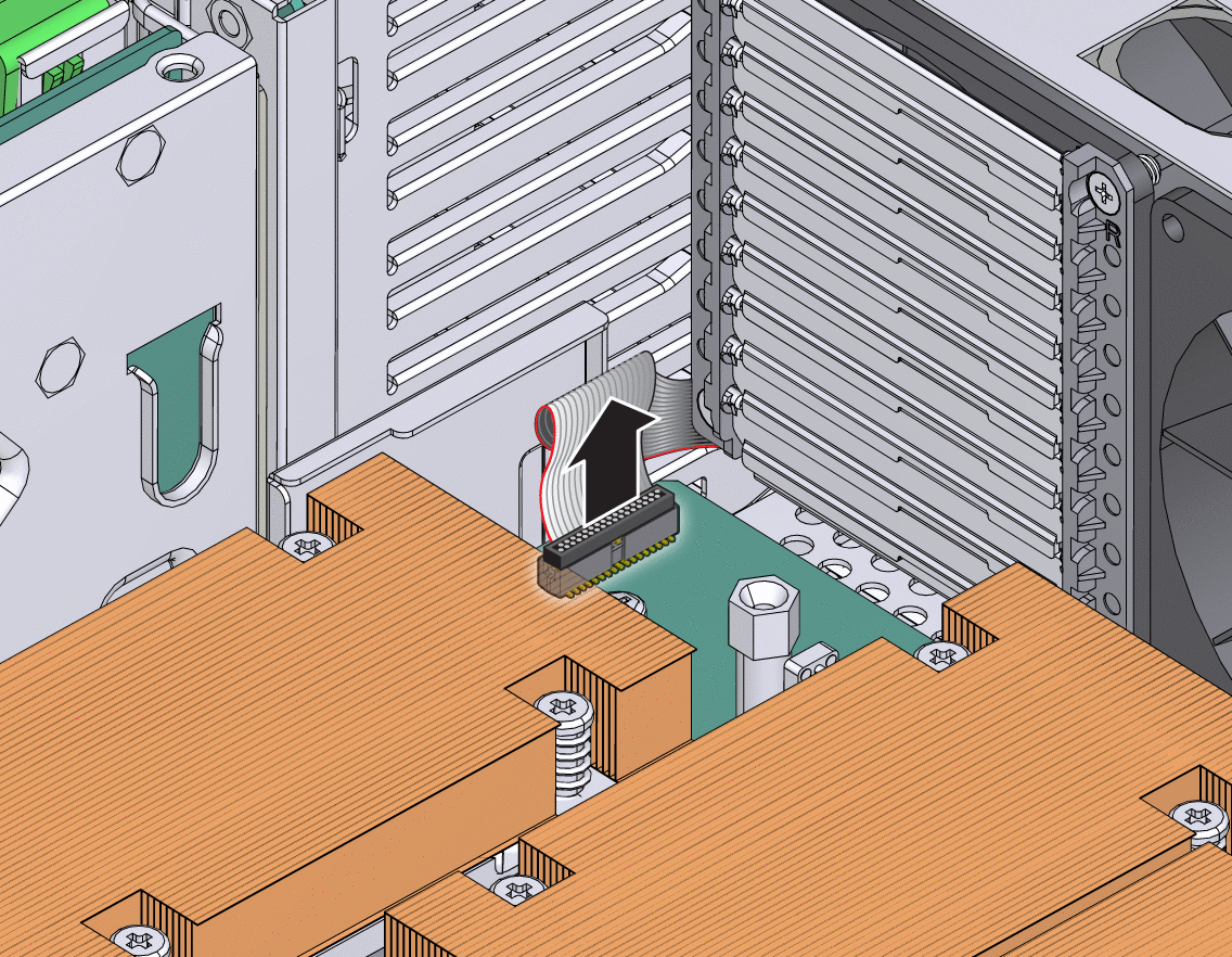
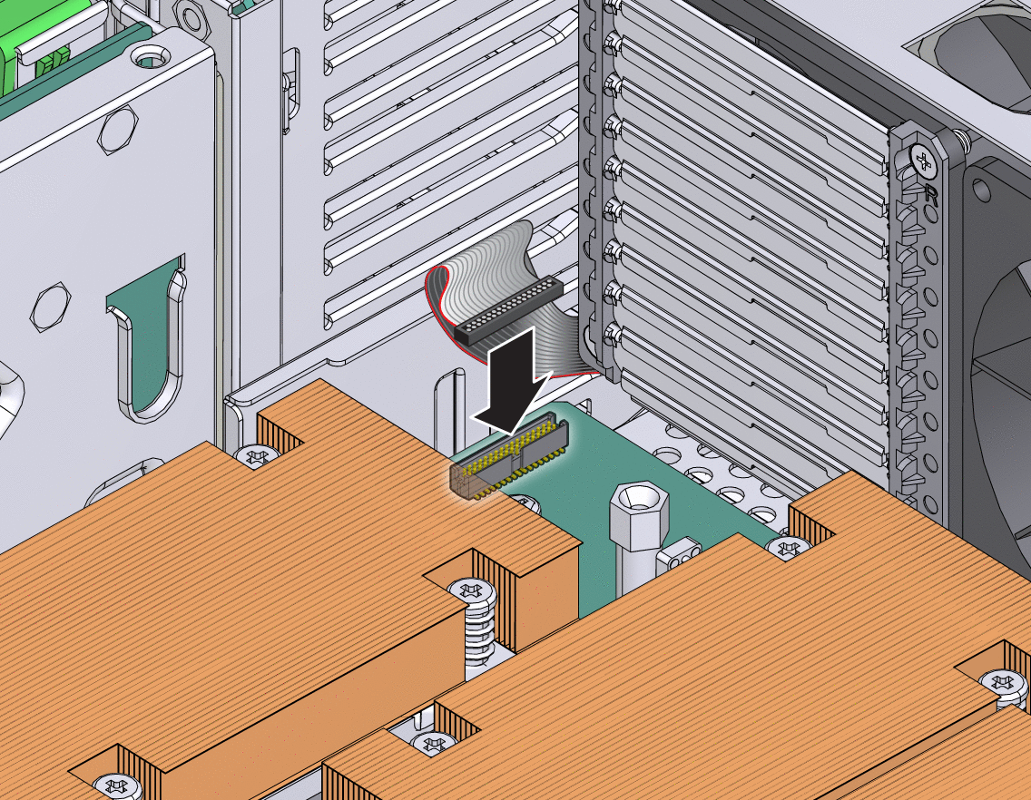
Disconnect the cable connected to the motherboard (FIGURE 3-28).
Loosen or remove the screws that secure the motherboard assembly to the chassis (FIGURE 3-29).
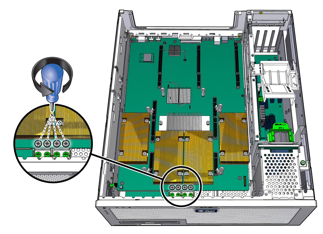
Loosen the two captive screws at the center of the motherboard assembly (FIGURE 3-29).
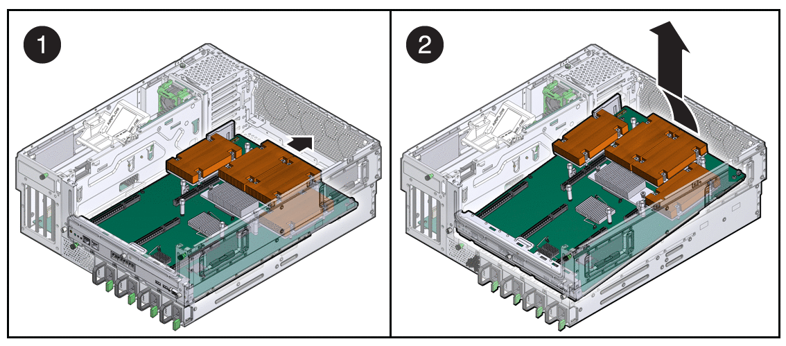
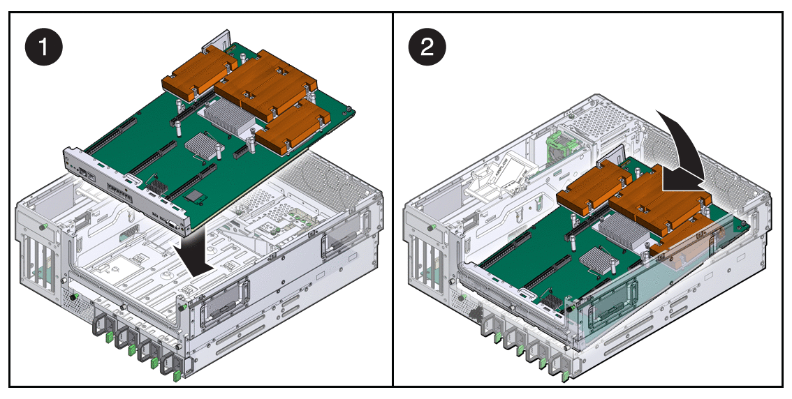
Lift slighty and slide the motherboard assembly forward approximately one inch (25.4 mm) (FIGURE 3-30).
Lift up on the right edge to approximately a 45 degree angle (FIGURE 3-30).
Remove the motherboard assembly from the chassis (FIGURE 3-30).
Remove the replacement motherboard assembly from its packaging, and place it on an antistatic mat.
Lower the left edge of the motherboard assembly into the chassis, then the entire board, and while slightly elevated, slide the motherboard assembly to the back of the chassis (FIGURE 3-31).
Align the motherboard assembly screw holes over the chassis standoffs.
Tighten the captive screws at the center of the motherboard assembly (FIGURE 3-32).
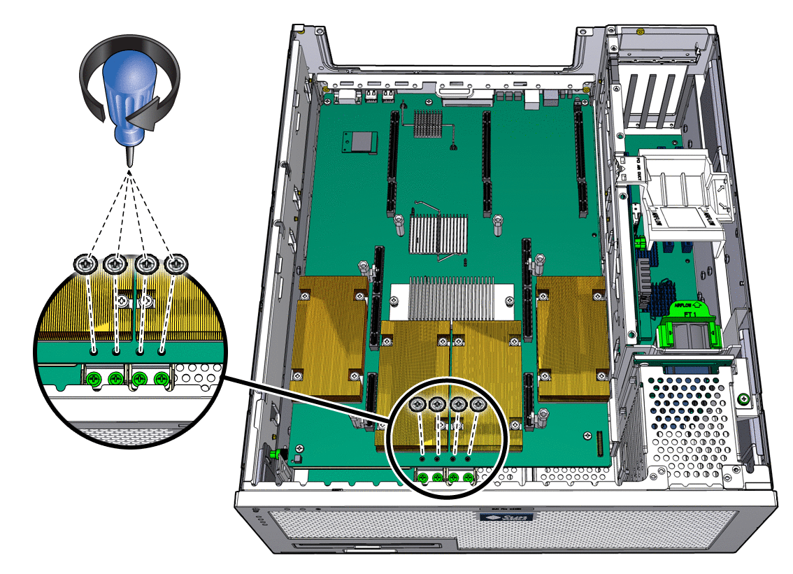
Install the two power screws and four other screws that secure the motherboard assembly to the chassis (FIGURE 3-32).
Reconnect the cable to the connector on the motherboard assembly (FIGURE 3-33):
Replace system fan 0 (see Replacing System Fan 0).
See Chapter 4 to perform the tasks needed to bring the server back online.
To remove the power board, you must remove the following components as part of preparing the server for power board replacement:
PCI mezzanine (see Remove the PCI Mezzanine)
System fan 0 (see Replacing System Fan 0)
Optical media drive (see Replacing the Optical Media Drive)
Motherboard (see Remove the Motherboard Assembly)
Prepare the server for power board removal.
See Chapter 2.
Remove the screws that secure the power board to the chassis (FIGURE 3-34).
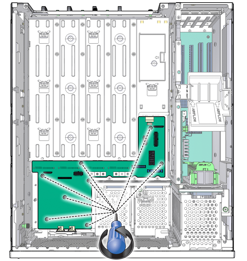
Lift the power board out of the chassis, and set it aside on an antistatic mat.
Continue to Install the Power Board.
Remove the replacement power board from its packaging and place it on an antistatic mat.
Lower the power board into the chassis, aligning the board’s holes with the standoffs in the chassis.
Install the screws firmly to secure the power board to the chassis.
Perform the installation instructions in the following sections:
See Chapter 4 to perform the tasks needed to bring the server back online.
Copyright © 2008, Sun Microsystems, Inc. All rights reserved.