| C H A P T E R 2 |
|
Setting Up the Sun Fire X2200 M2 Server Software |
This chapter describes how to set up the Embedded Lights Out Manager (LOM) service processor (SP). It includes information on the following topics:
The Sun Fire X2200 M2 server Embedded LOM SP provides powerful tools for managing your server. It consists of four components, three of which are on your host server and one that is on the client system that accesses your host server. The four components are as follows:
These interfaces call the same underlying system management functions on your service processor, so you can choose to work with one or more of these interfaces to integrate with the other management interfaces running in your data center.
Sun Microsystems has configured the service processor hardware and firmware on your server to reflect the most common default settings used in the field. It is unlikely that you will need to change most of these defaults.
This section describes two methods for connecting to your Embedded LOM SP to perform initial setup and configuration. Use the procedure that you prefer.
|
Note - If you do not have a DHCP server available, you will need to configure the Embedded LOM using a serial connection. |
|
You can configure the Embedded LOM SP at any time by connecting a terminal or PC running terminal emulation software to the server serial port. Use this procedure to establish a serial connection to the Embedded LOM SP and to perform initial configuration of Embedded LOM firmware.
|
Note - This procedure assumes that you have already completed the hardware setup and power-on for your server, as described in Chapter 1 of this guide. |
1. Verify that your terminal, laptop, or terminal server is operational.
2. Configure the terminal device or the terminal emulation software running on a laptop or PC to the following settings:
3. Connect a null serial modem cable from the DB9 serial port on the server's back panel to a terminal device.
See FIGURE 1-2 for the position of the serial port on the back panel.
4. Press Enter on the terminal device to establish a connection between the terminal device and the Embedded LOM SP.
|
Note - If you connect to the serial port on the Embedded LOM before it has been powered on or during its power-on sequence, boot up messages display. |
The Embedded LOM eventually displays a login prompt.
5. Log in to the Embedded LOM SP and type the default user name, root, with the default password, changeme.
Once you have successfully logged in, the Embedded LOM displays its default command prompt:
6. Do one of the following, depending on whether or not the DHCP server is present:
|
Note - The SP IP address defaults to DHCP. If a DHCP address is not found, the SP will default to a static IP address. |
|
Note - Be sure to record the IP address assigned to the Embedded LOM. |
7. When you apply standby power to the server, the Embedded LOM SP output is displayed. To launch a console to view the system output, type the following command:
|
Note - You can switch back to the Embedded LOM command-line interface (CLI) from the serial console by entering the following key sequence: Esc + Shift + 9. While logged in to the Embedded LOM, you can type the CLI command show /SP/network to view the current Embedded LOM network configuration. For instructions on configuring static network settings using the CLI, see To Configure the Embedded LOM SP Using a Static IP Address. |
8. Proceed to Configuring or Installing System Software.
The Embedded LOM SP offers several interfaces to support system management on your server. Before you take advantage of those interfaces over your Ethernet local area network (LAN), you need to do the following:
|
Note - As an alternative to having your DHCP server assign an IP address to your SP, you can also assign a static IP address to it. For this procedure, see To Configure the Embedded LOM SP Using a Static IP Address. |
|
Establishing an Ethernet management connection involves assigning a static or dynamic IP address to the RJ-45 Ethernet Management port. Use this procedure to configure the SP and the DHCP server in your data center to support DHCP connections.
|
Note - This procedure assumes that you have already completed the hardware setup and have applied standby power for your server, as described in Chapter 1 of this guide. |
1. Verify that your DHCP server is configured to accept new media access control (MAC) addresses.
MAC addresses are 12-digit hexadecimal strings in the format xx:xx:xx:xx:xx:xx where x represents a single hexadecimal letter (0-9, A-F, a-f).
2. Connect an Ethernet cable to the RJ-45 NET MGT Ethernet port on your server. See FIGURE 1-2.
If the SP is not using static IP addresses, it broadcasts a DHCPDISCOVER packet with the ID of its MAC address. A DHCP server on your LAN returns a DHCPOFFER packet containing an IP address and other information. The SP then manages its "lease" of that IP address assigned to it by the DHCP server.
3. Obtain the SP MAC address from one of the following locations. Write down that address for future reference.
4. Obtain the SP IP address from one of the following locations. Record the IP address for future reference.
a. Log in to your DHCP server and view its DHCP log file.
b. Identify the IP address in the log file that corresponds to the MAC address of your SP.
Typically, DHCP log file entries are individual lines with the following comma-separated fields:
ID, Date, Time, Description, IP Address, Host Name, MAC Address
Locate the MAC address of your SP in the MAC Address (seventh) field of the correct DHCP file entry and record the corresponding value of the IP Address (fifth) field. This is the IP address that you must use to access the system management firmware applications on your SP.
5. Open a session to the SP using the IP address that you obtained in Step 4.
Each SP firmware application requires a different browser or shell.
Once you have entered the default password for the SP, changeme, you can enter commands to manage user accounts or to monitor the status of devices on your server.

6. Enter the default user name, root, with the default password, changeme, at the CLI or GUI prompt to log in to the Embedded LOM SP.

7. Type Embedded LOM SP commands in the CLI or navigate to Embedded LOM web GUI pages to configure your Embedded LOM SP. See the Embedded Lights Out Manager Administration Guide for more details on how to use the Embedded LOM GUI for server management.
8. Continue with Configuring or Installing System Software.
|
As an alternative to having your DHCP server assign an IP address to your SP, you can also assign a static IP address to it. You can do this using the web GUI, or using the CLI over the network or serial port. Use the procedure that you prefer:
The following procedure describes how to configure static IP addresses using the web GUI.
1. Determine the current IP address of the SP from one of the following locations:
2. Connect to the SP through a web browser running on a remote system.
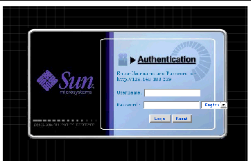
3. Log in to the web GUI using the default user name, root, and the default password, changeme.
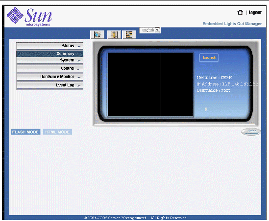
The initial Embedded LOM screen displays.

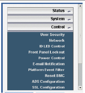
4. Click the Control button to display the drop-down menu.

5. Select Network from the drop-down menu to display information about the current network configuration of your Embedded LOM SP.
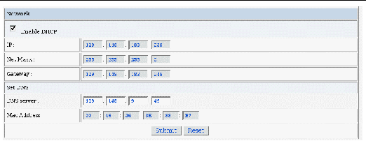
The Network Settings Page displays.

6. Select the Enable DHCP box to disable it, and enter your static IP address information.
1. Log into the CLI using SSH or by connecting to the serial port.
To establish a SSH connection to the Embedded LOM SP CLI, type the appropriate connection command in the SSH application. For example, to connect to the SP with the DHCP-assigned IP address of 129.144.82.20, type the following command:
2. Type the following commands, using your own addresses in place of the examples below:
(The addresses shown in the commands below are examples.)
set /SP/AgentInfo DhcpConfigured=disable set /SP/AgentInfo NetMask=255.255.255.0 set /SP/AgentInfo Gateway=129.144.82.254 set /SP/AgentInfo IpAddress=129.144.82.26 |
The BIOS has two options for serial redirection after the Embedded LOM SP has been configured:
By default, the BIOS is set to redirect its serial output to the SP. If you would rather not have to issue an SP CLI command to access the BIOS redirected serial stream, you can change the BIOS configuration option to make the default serial redirection be from the BIOS rather than the SP.
To change the BIOS to display system information to the serial console:
1. Reboot the system by typing the following command from the SP CLI:
set /SP/SystemInfo/CtrlInfo PowerCtrl=reset
2. Launch the console from the SP using the following command:
Make sure to watch the output carefully, so you won't miss the intial BIOS screens.
|
Note - Refer to TABLE 2-1 for information on Esc sequences for the serial terminal to replace the function keystrokes in the following steps. |
3. Press F2 to enter the BIOS on the console.
4. Change the following BIOS option under IPMI 2.0 configuration from SP to System.
5. Press F10 to save your changes and reboot.
The serial redirection will now always display the system output.
You will be able to view and interact with a character-based representation of the BIOS screens as displayed on the video port. See TABLE 2-1 for a list of keystrokes that are remapped for use over a serial terminal.
If your server has at least one hard drive installed, the server might have the Solaris 10 Operating System and additional software preinstalled.
Additional software will be preinstalled on the Sun Fire X2200 M2 server, including Sun Java Enterprise System (JES) and Sun
 Studio. See the following table for where to find information and downloads for these software products.
The developer software, software updates, documentation, and more, are now freely available at the following sites.
If you do not plan to use an operating system (OS) that is preinstalled on your Sun Fire X2200 M2 server, install your preferred OS at this time. If the Solaris 10 OS is preinstalled on the primary boot drive, you will need to remove the OS using the Erase Primary Boot Disk utility on the Tools and Drivers CD.
See the Sun Fire X2200 M2 Server Operating System Installation Guide, 819-6599, for more information on erasing the primary boot disk and installing an operating system onto the server.
The following sources can help you with Sun Fire X2200 M2 server-specific information for installing an operating system on the Sun Fire X2200 M2 server:
http://www.sun.com/documentation
http://www.sun.com/servers/x64/x2200/downloads.jsp
Copyright © 2007, Sun Microsystems, Inc. All Rights Reserved.