| C H A P T E R 3 |
 Servicing Server Module Components
 |
This chapter describes how to replace components in the Sun Blade X6275 server module.
| Note - Before performing any of the procedures in this chapter, perform the procedures described in Chapter 2, Preparing to Service the System. |
The following topics are covered in this chapter:
This section describes how to diagnose and replace faulty DDR3 DIMMs and Sun Flash Modules (FMODs). The following topics are covered:
| Note - CRU: These customer replaceable units can be replaced by anyone. |

|
Caution - This procedure requires that you handle components that are sensitive to static discharge. This sensitivity can cause the component to fail. To avoid damage, ensure that you follow antistatic practices. See Electrostatic Discharge Safety Measures. |
The amber Service Action Required LED lights if the server module detects a DIMM fault.
1. Prepare the server module for service.
a. Power off both server module compute nodes.
See Powering Off the Server Module.
b. Remove the server module from the Sun Blade chassis. Place it on a flat surface.
See Removing the Server Module From the Sun Blade Chassis.
c. Attach an antistatic wrist strap.
See Performing Electrostatic Discharge and Antistatic Prevention Measures.
d. Remove the server module top cover.
See Removing the Server Module Top Cover.
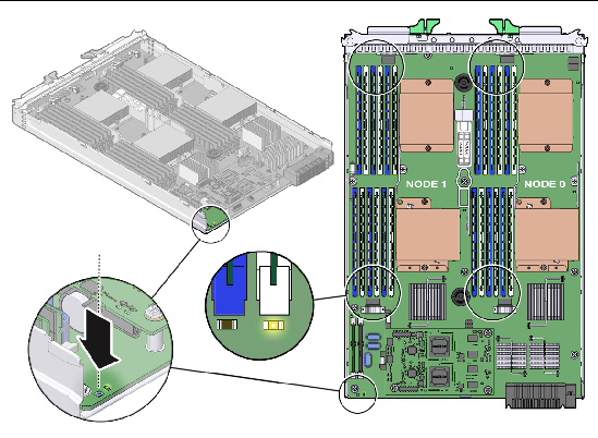
2. Press and hold the Remind button on the motherboard to identify a faulty DIMM. An amber LED lights near the faulty DIMM. See FIGURE 3-1.
3. Note the location of faulty DDR3 DIMMs slots on the motherboard of the server module.
DIMMs are identified with a corresponding amber LED on the motherboard.
4. Ensure that all DIMMs are seated correctly in their slots.
If re-seating the DIMM does not fix the problem, remove and replace the faulty DIMM.
FIGURE 3-1 DIMM Fault LEDs and Remind Button Locations
Use the DDR3 DIMM guidelines, FIGURE 3-2, and FIGURE 3-3 to help you plan the memory configuration of your server module.
FIGURE 3-2 shows the DIMM population method.
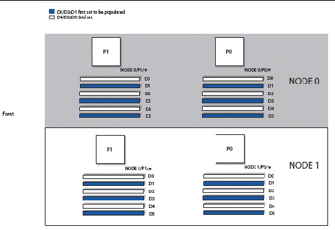
The DDR3 DIMM population rules for the Sun Blade X6275 Server Module are as follows:
12 DDR3 DIMMs per server module or 24 DDR3 DIMMs (2 DDR3 DIMMs per memory channel) per server module configurations are supported.
| Note - Only 3 DIMMs and 6 DIMMs per installed processor are supported. |
Each processor contains a separate memory controller.
For example, populate D5/D3/D1 first; then D4/D2/D0 second.
DIMM slots D4/D2/D0 are empty, and
DIMM slots D5/D3/D1 are installed with 1 or 2 rank 1333 MHz DDR3 DIMMs
DIMM slots D4/D2/D0 are installed with 1 or 2 rank DDR3 DIMMs (1066 or 1333 MHz), and
DIMM slots D5/D3/D1 are installed with 1 or 2 rank DDR3 DIMMs (1066 or 1333 MHz)
Regarding Intel Xeon 5500 sequence memory performance, rank switching delay is higher when switching between DIMMs on a channel than it is when switching between ranks on the same DIMM. Therefore it is preferable to populate one dual-rank 4GB DIMM rather than two single-rank DIMMs per channel.
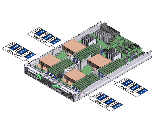
FIGURE 3-3 shows the DIMM numbering and positions.
FIGURE 3-3 DIMM Numbering and Position
1. Prepare the server module for service.
a. Power off both server module compute nodes.
See Powering Off the Server Module.
b. Remove the server module from the Sun Blade chassis. Place it on a flat surface.
See Removing the Server Module From the Sun Blade Chassis.
c. Attach an antistatic wrist strap.
See Performing Electrostatic Discharge and Antistatic Prevention Measures.
d. Remove the server module top cover.
See Removing the Server Module Top Cover.

|
Caution - Ensure that all power is removed from the server module before removing or installing DDR3 DIMMs, or damage to the DDR3 DIMMs might occur. |
2. Press the Remind button on the motherboard to locate the failed DIMMs.
See FIGURE 3-1 for the Remind button location.
3. Locate the DIMM slot on the motherboard.
A lit LED next to a DIMM slot indicates a faulty DIMM.
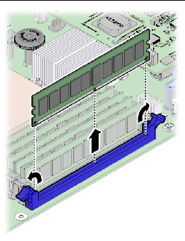
4. Rotate both DIMM slot ejectors outward as far as they will go.
This action partially ejects the DIMM from the slot.
5. Carefully lift the DIMM straight up to remove it from the slot. See FIGURE 3-4.
Always replace a DDR3 DIMM with the same Sun part number as the failed DDR3 DIMM.
| Tip - See DDR3 DIMM Guidelines for information about configuring the DDR3 DIMMs. |
1. Unpack the replacement DDR3 DIMMs and place them on an antistatic mat.
2. Ensure that the ejector tabs are in the open position.
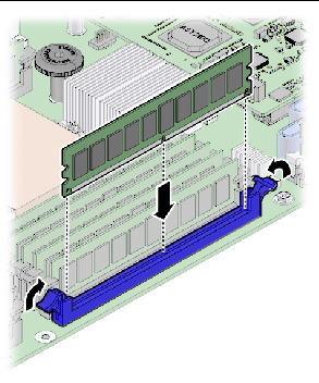
3. Line up the replacement DDR3 DIMM with the connector. See FIGURE 3-5.
Align the DDR3 DIMM notch with the key in the connector. This ensures that the DDR3 DIMM is oriented correctly.
4. Push the DDR3 DIMM into the connector until the ejector tabs lock the DDR3 DIMM in place.

|
Caution - If the DDR3 DIMM does not easily seat into the connector, verify that the orientation of the DDR3 DIMM is as shown in FIGURE 3-5. If the orientation is reversed, damage to the DDR3 DIMM might occur. |
5. Repeat Step 2 through Step 4 until all replacement DDR3 DIMMs are installed.
6. Return the server module to operation.
a. Install the server module top cover.
See Installing the Server Module Top Cover.
b. Insert the server module into the Sun Blade chassis.
See Reinstalling the Server Module in the Sun Blade Chassis.
c. Power on the server module.
See Powering On the Server Module.
7. Verify and view DIMM component information.
Use the ILOM web interface or CLI. Refer to the corresponding ILOM documentation collection.
FIGURE 3-5 Installing DDR3 DIMMs
Two Flash Module (FMOD) slots are located on the motherboard of the server module.
| Note - CRU: This customer replaceable unit can be replaced by anyone. |
1. If necessary, back up any data that is contained on the Flash Module (FMOD).
2. Prepare the server module for service.
a. Power off both server module compute nodes.
See Powering Off the Server Module.
b. Remove the server module from the Sun Blade chassis. Place it on a flat surface.
See Removing the Server Module From the Sun Blade Chassis.
c. Attach an antistatic wrist strap.
See Performing Electrostatic Discharge and Antistatic Prevention Measures.
d. Remove the server module top cover.
See Removing the Server Module Top Cover.
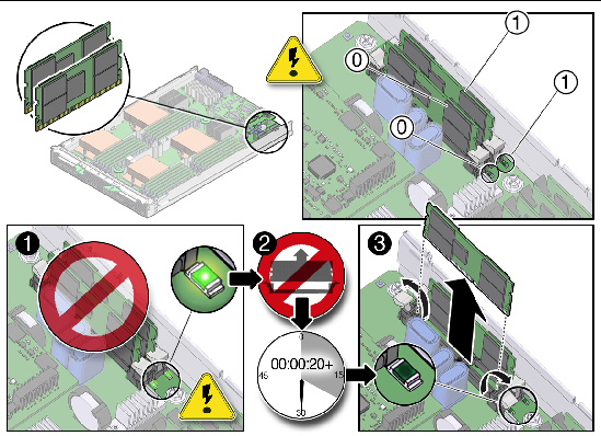
3. Locate the FMOD slot on the motherboard. See FIGURE 3-6, [1].
A lit green LED next to an FMOD slot indicates that the FMOD slot is powered on. It does not indicate a faulty FMOD. Wait for the FMOD LED to go off before installing or removing an FMOD to avoid damaging the FMOD.
4. Wait for the green FMOD LED to go out (about 20 seconds). See FIGURE 3-6, [2].

|
Caution - Do not remove or insert the flash module until the green LED goes out. Damage to the flash module can occur if the module is removed while the green LED is lit. |
5. Rotate both FMOD slot ejectors outward as far as they will go.
This action partially ejects the FMOD from the slot.
6. Carefully lift the FMOD straight up to remove it from the slot. See FIGURE 3-6, [3].
FIGURE 3-6 Removing Flash Modules

|
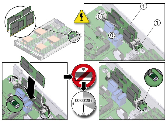
Caution - Do not remove or insert the flash module until the green LED goes out. Damage to the flash module can occur if the FMOD is installed while the green LED is lit. |
Flash modules can be safely inserted into empty FMOD slots after FMOD power LEDs go off.
1. Unpack the replacement flash modules and place them on an antistatic mat.
2. Ensure that the ejector tabs are in the open position.
3. Line up the flash module with the connector. See FIGURE 3-7.
Align the FMOD notch with the key in the connector. This ensures that the FMOD is oriented correctly.
4. Push the flash module into the connector until the ejector tabs lock the FMOD in place.
If the FMOD does not easily seat into the connector, verify that the orientation of the FMOD is as shown in FIGURE 3-7. If the orientation is reversed, damage to the FMOD might occur.
5. Repeat Step 2 through Step 4 until all flash modules are installed.
6. Return the server module to operation.
a. Install the server module top cover.
See Installing the Server Module Top Cover.
b. Insert the server module into the Sun Blade chassis.
See Reinstalling the Server Module in the Sun Blade Chassis.
c. Power on the server module.
See Powering On the Server Module.
7. Verify and view flash module component information.
Use the ILOM web interface or CLI. Refer to the corresponding ILOM documentation collection.
FIGURE 3-7 Replacing Flash Modules
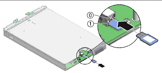
The USB drives might contain the boot OS. Two USB drive ports are located on the rear of the server module motherboard, under the SP board. The top USB port is for compute node 0. The bottom USB port is for compute node 1.
| Note - CRU: This customer replaceable unit can be replaced by anyone. |
1. If necessary, back up any data that is contained on the USB drives.
2. Prepare the server module for service.
a. Power off both server module compute nodes.
See Powering Off the Server Module.
b. Remove the server module from the Sun Blade chassis. Place it on a flat surface.
See Removing the Server Module From the Sun Blade Chassis.
c. Attach an antistatic wrist strap.
See Performing Electrostatic Discharge and Antistatic Prevention Measures.
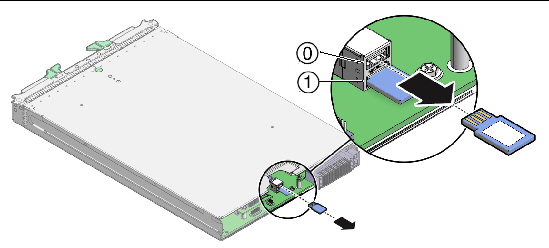
3. Locate the USB port on the back of the motherboard. See FIGURE 3-8.
4. Grasp the USB drive, and pull the USB drive out.
5. Repeat Step 4 for the second USB Drive.
FIGURE 3-8 Removing USB Drives From Ports
1. Unpack the replacement USB drives and place them on an antistatic mat.
2. Push the USB drive into the port. The USB drive's gold fingers should face up. See FIGURE 3-9.
| Note - If any resistance is encountered, the USB drive might be upside down. Rotate the drive and try again. The label is normally on top. |
3. Repeat Step 2 for the second USB drive.
4. Return the server module to operation.
a. Insert the server module into the Sun Blade chassis.
See Reinstalling the Server Module in the Sun Blade Chassis.
b. Power on the server module.
See Powering On the Server Module.
5. Verify and view component information.
Use the ILOM web interface or CLI. Refer to the corresponding ILOM documentation collection.
FIGURE 3-9 Replacing the USB Drives
Use this procedure to replace a processor or a processor and heat sink. You need to identify the failed processor, remove the heat sink and processor, and then install replacement parts.
When replacing processors, do not install processors of different speeds on the same motherboard.
| Note - Position P0 and P1 must always contain a processor. |
| Note - The processor is a FRU and must be replaced only by qualified service technicians. Contact your Sun Service representative for assistance. |
1. Prepare the server module for service.
a. Power off both server module compute nodes.
See Powering Off the Server Module.
b. Remove the server module from the Sun Blade chassis. Place it on a flat surface.
See Removing the Server Module From the Sun Blade Chassis.
c. Attach an antistatic wrist strap.
See Performing Electrostatic Discharge and Antistatic Prevention Measures.
d. Remove the server module top cover.
See Removing the Server Module Top Cover.
2. Press the Remind button on the motherboard. See FIGURE 3-10.
A failed processor is identified by a lit processor fault LED. See FIGURE 3-10.
3. Identify which processor and heat sink you are replacing.
The numbering of the processors and corresponding processor fault LEDs on the motherboard are shown in FIGURE 3-10.
FIGURE 3-10 Processor Fault LEDs and Remind Button Locations

An illustration showing the internal numbering designation of the CPUs. Also shown are the CPU fault LEDs.
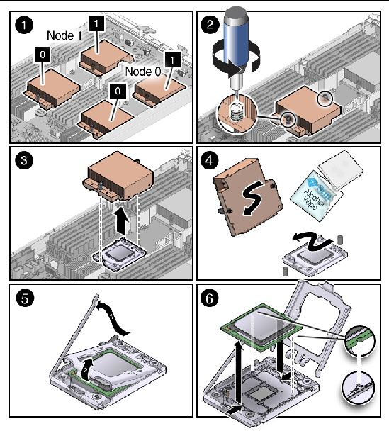
To remove a processor and heat sink from the motherboard:
1. Identify the processor(s) to be removed, as required. See FIGURE 3-11, [1].
See Identifying a Faulty Processor
2. Gently press down on the top of the heat sink to counteract the pressure of the captive spring-loaded screws that secure the heat sink to the motherboard.
3. Alternately loosen each of the two spring-loaded mounting screws that secure the heat sink to the motherboard. Use a #2 Phillips screwdriver. See FIGURE 3-11, [2]. Turn each screw 180 degrees at a time.
4. To separate the heat sink from the top of the processor, gently wiggle the heat sink left and right, while pulling upward. See FIGURE 3-11, [3].
A thin layer of thermal compound separates the heat sink and the processor. This compound also acts as an adhesive.
5. After you separate the heat sink from the processor, set the heat sink on a flat surface, away from the server module.
a. Use an alcohol pad to completely clean all of the old thermal compound from the heat sink.
b. Clean any dust from the heat sink fins.
Do not allow the thermal compound to contaminate the work space or other components.
6. Use an alcohol pad to completely clean all of the old thermal compound from the component surface, before you remove the processor. See FIGURE 3-11, [4].
You will need to apply new thermal compound when you reinstall the heat sink in Installing a Processor and Heat Sink.
7. Lift the processor lever to the fully open position. See FIGURE 3-11, [5].
a. Holding down the processor clamp, carefully release the spring lever.
b. Lift the processor clamp up and away from the processor. Leave it open.
8. Lift the processor out of the socket, leaving the lever in the open position. See FIGURE 3-11, [6].
FIGURE 3-11 Removing a Processor
To install a new processor or an existing processor:
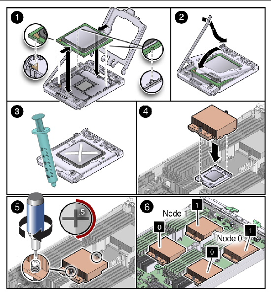
1. Ensure that the processor socket release lever is in the fully open position. See FIGURE 3-12, [1].
2. Align the processor over the processor socket. See FIGURE 3-12, [2].
Refer to the notches on the processor and the processor socket for proper alignment.
3. Gently set the processor on the socket. See FIGURE 3-12, [1].
When properly aligned, the processor sits flat in the processor socket and has minimal side-to-side movement.
4. Lower the processor clamp, and then latch the lever. See FIGURE 3-12, [2].
This action secures the processor in the socket.
5. Ensure that the old thermal compound has been removed from the component surface and heat sink.
Use an alcohol pad to clean old thermal compound from the component surface. See Removing a Processor and Heat Sink, Step 6.
6. Using one syringe of thermal compound (500 mg [0.2 ml]), carefully apply the compound to the top of the processor in an X pattern, stopping short of the corners. See FIGURE 3-12, [3].
7. Carefully position heat sink over the processor, and align the heat sink screws with the screw holes in the motherboard. See FIGURE 3-12, [4].
8. Lower the heat sink onto the processor.
9. Gently press down on the top of the heat sink to counteract the pressure of the captive spring-loaded screws, and use a #2 torque screwdriver to alternately tighten each screw, 180 degrees at a time, until tight at 8 inch pounds. See FIGURE 3-12, [5].
10. Repeat Step 1 through Step 9 until all processors are installed. See FIGURE 3-12, [6].
11. Return the server module to operation.
a. Install the server module top cover.
See Installing the Server Module Top Cover.
b. Insert the server module into the Sun Blade chassis.
See Reinstalling the Server Module in the Sun Blade Chassis.
c. Power on the server module.
See Powering On the Server Module.
12. Update the BIOS and firmware.
Refer to the corresponding ILOM supplement.
FIGURE 3-12 Replacing a Processor
This section provides instructions for replacing a damaged service processor (SP) unit.
1. Prepare the server module for service.
a. Power off both server module compute nodes.
See Powering Off the Server Module.
b. Remove the server module from the Sun Blade chassis. Place it on a flat surface.
See Removing the Server Module From the Sun Blade Chassis.
c. Attach an antistatic wrist strap.
See Performing Electrostatic Discharge and Antistatic Prevention Measures.
d. Remove the server module top cover.
See Removing the Server Module Top Cover.
2. Remove the new service processor from its shipping container and place it on an antistatic surface.
3. Remove the three screws that fasten the old service processor to the motherboard (FIGURE 3-13).
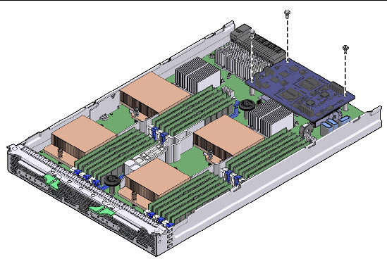
4. Lift the service processor straight up to remove it.
5. Lower the new service processor onto the motherboard.
Lower the service processor straight onto the connector. Do not force it.
6. Return the server module to operation.
a. Install the server module top cover on the new motherboard.
See Installing the Server Module Top Cover.
b. Insert the server module into the Sun Blade chassis.
See Reinstalling the Server Module in the Sun Blade Chassis.
c. Power on the server module.
See Powering On the Server Module.
| Note - Because the MAC address of the SP is stored on the motherboard, after you replace the SP, its original MAC address is restored automatically. |
7. Update the system with the BIOS/ILOM firmware package you downloaded earlier.
This will ensure that both the BIOS and ILOM firmware (which are packaged and tested together) are at a supported level.
Refer to the corresponding ILOM supplement for your server for details on updating firmware.
The motherboard is shipped installed in an empty server module chassis. Do not remove the motherboard from the server module chassis. Instead, remove components from the old server module chassis assembly, and install these components into the new motherboard and server module chassis assembly.
| Note - The server module motherboard assembly is a FRU and must be replaced only by qualified service technicians. Contact your Sun Service representative for assistance. |
1. Prepare the server module for service.
a. Power off both server module compute nodes.
See Powering Off the Server Module.
b. Remove the server module from the Sun Blade chassis. Place it on a flat surface.
See Removing the Server Module From the Sun Blade Chassis.
c. Attach an antistatic wrist strap.
See Performing Electrostatic Discharge and Antistatic Prevention Measures.
d. Remove the server module top cover.
See Removing the Server Module Top Cover.
2. Remove reusable components from the server module motherboard.
3. Install the components on the new server module motherboard assembly.
4. Return the server module to operation.
a. Install the server module top cover on the new motherboard.
See Installing the Server Module Top Cover.
b. Insert the server module into the Sun Blade chassis.
See Reinstalling the Server Module in the Sun Blade Chassis.
c. Power on the server module.
See Powering On the Server Module.
5. Restore FRUID information (Oracle Service personnel only):
a. Log in to escalation mode with the escalation mode password.
# servicetool --fru_product_serial_number
The following output displays:
Servicetool is going to update the product serial number in mainboard and pdb FRUs.
Do you want to continue (y|n)?
The following output displays:
When entering values, do not use quotes; If you require embedded quotes, escape them with three backslashes;e.g.\\\"
What is the new product serial number?
d. Type in the new product serial number.
The following is an example of the output that displays:
The product serial number has been updated.
The new serial number is: "1234567890"
e. To allow the SP to see the new serial number, reset the SP. Type:
This reboots the SP only and will close any ssh connections to the SP.
6. Update the system with the BIOS/ILOM firmware package you downloaded earlier.
This will ensure that both the BIOS and ILOM firmware (which are packaged and tested together) are at a supported level. A BIOS/ILOM firmware package can be downloaded for your system from:
Refer to the corresponding ILOM supplement for your server for details on updating firmware.
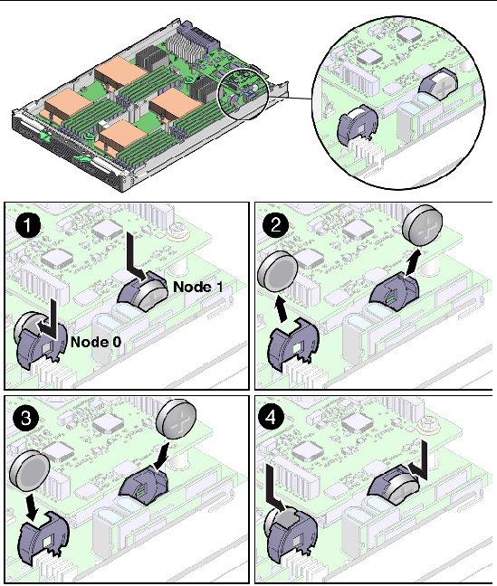
Two Real-Time-Clock (RTC) system CR2032 batteries, one per compute node, are located on the motherboard.
| Note - CRU: This customer replaceable unit can be replaced by anyone. |
1. Prepare the server module for service.
a. Power off both server module compute nodes.
See Powering Off the Server Module.
b. Remove the server module from the Sun Blade chassis. Place it on a flat surface.
See Removing the Server Module From the Sun Blade Chassis.
c. Attach an antistatic wrist strap.
See Performing Electrostatic Discharge and Antistatic Prevention Measures.
d. Remove the server module top cover.
See Removing the Server Module Top Cover.
2. Remove the battery by gently pulling the clip away from the edge of the battery and lifting the battery straight up. See FIGURE 3-14 [1], [2].
3. Insert the battery by pressing the battery straight down and gently pushing the clip towards the edge of the battery. See FIGURE 3-14 [3], [4].
Install the new battery in the holder with the same orientation (polarity) as the battery that you removed.
The positive polarity, marked with a “+” symbol, faces outward.
The BIOS settings revert to the default settings.
See Resetting Passwords and Clearing CMOS NVRAM.
5. Return the server module to operation.
a. Install the server module top cover.
See Installing the Server Module Top Cover.
b. Insert the server module into the Sun Blade chassis.
See Reinstalling the Server Module in the Sun Blade Chassis.
c. Power on the server module.
See Powering On the Server Module.
FIGURE 3-14 Removing the RTC Batteries
The following topics are covered:
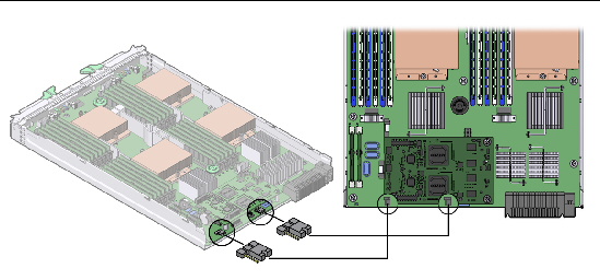
You can reset a password and clear both the CMOS NVRAM and BIOS password by changing the J42_1 (compute node 0) and J42_2 (compute node 1) jumper positions. FIGURE 3-15 shows jumpers in the normal (1-2) position.
FIGURE 3-15 Sun Blade X6275 Server Module Rear Panel Jumper Locations
The BIOS PCI screens allow you to clear NVRAM during server module boot.
1. Access the BIOS. Press F2 during server module boot.
See Configuring BIOS Settings.
1. Prepare the server module for service.
a. Power off both server module compute nodes.
See Powering Off the Server Module.
b. Remove the server module from the Sun Blade chassis. Place it on a flat surface.
See Removing the Server Module From the Sun Blade Chassis.
c. Attach an antistatic wrist strap.
See Performing Electrostatic Discharge and Antistatic Prevention Measures.
d. Remove the server module top cover.
See Removing the Server Module Top Cover.
2. Locate the jumpers J42_1 (compute node 0) and J42_2 (compute node 1) jumpers on the rear of the motherboard. The jumper default position is 1-2.
FIGURE 3-16 shows the jumpers.
FIGURE 3-16 Sun Blade X6275 Server Module CMOS Reset Jumper Settings
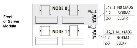
3. Place the jumper on position 2-3 for 10 seconds.
4. Remove the jumper from position 2-3, and replace it back to its original position 1-2.
5. Repeat for the second compute node, if required.
6. Return the server module to operation.
a. Install the server module top cover.
See Installing the Server Module Top Cover.
b. Insert the server module into the Sun Blade chassis.
See Reinstalling the Server Module in the Sun Blade Chassis.
c. Power on the server module.
See Powering On the Server Module.
Now, the BIOS password is reset and NVRAM is cleared.
If the SP (service processor) software becomes corrupted, you can reinstall the default SP software image. If an upgrade fails, or if the firmware image becomes corrupt, choose one of the following methods to recover the SP software:
Refer to the corresponding ILOM supplement for detailed preboot and IPMI information.
The preboot menu provides the ability to recover the ILOM firmware image by updating (flashing) the SP firmware.
Normally, you can update the SP using the ILOM CLI or the web interface. Refer to the Sun Integrated Lights Out Manager documentation for details.
If you are unable to access the ILOM to update the firmware, you can use this procedure to update it using the preboot menu.
You must have a valid .flash firmware image file on a tftp server. This file is available on the tools and drivers DVD, and on the Oracle download site:
| Note - Updating the SP firmware using the preboot menu requires a .flash file instead of the .pkg file used to update the SP from the ILOM. |
Refer to the corresponding ILOM supplement for detailed preboot menu and ILOM information.
2. Interrupt the ILOM boot process to access the preboot menu. Choose one of the following methods:
Manually by pressing the Locate button, or
Type xyzzy during a pause in the bootstrap process.
net flash IPaddress path/name.flash
IPaddress is the IP address of a tftp server
path is the path to the file relative to /tftpboot
name is the first part of the .flash file filename
Preboot> net flash 10.8.173.25 images/system-rom.flash
After a series of messages, the preboot prompt appears.
4. Use the reset command to restart the SP.
The preboot menu exits and the ILOM boots.

|
Caution - The server module might be powered off during the final stages of firmware update, when the BIOS is updated. |
 To upgrade ILOM firmware using IPMI, type:
# ipmiflash -H SP_IP -U root -P root_password write name.pkg config
ILOM-2_0_3_13_r42414-Sun_Blade_X6275.pkg
FOR SERVICE PERSONNEL ONLY. When replacing a motherboard assembly, FRU information must be obtained from the old motherboard assembly and transfered to the new motherboard assembly. Refer to the following:
|
| Note - This task is for Oracle Service personnel only. |
The Service Mode prompt appears.
2. At the Service Mode command line, enter the following command:
|
| Note - This task is for Oracle Service personnel only. |
The Service Mode prompt appears.
2. At the Service Mode command line, enter the following command:
This command performs a backup of current TLI (Top Level Identifier) and ILOM records.

Copyright © 2012, Oracle and/or its affiliates. All rights reserved.