| C H A P T E R 1 |
|
Before You Begin |
Firmware is the intelligence behind a RAID controller. It provides the underlying functionality of the controller, which is presented directly by the firmware menu options and is also used by the command-line interface (CLI), Sun StorEdge Configuration Service, and third-party applications that directly or indirectly use information passed bidirectionally through the firmware's external interface (EI).
Firmware is installed or "flashed" into the array hardware before it is shipped. At any time, you can download and install patches that include later versions of the firmware to take advantage of increased functionality.
Refer to the release notes for your array for an overview of the latest functionality as well as for instructions on how to download and install these patches. Refer to the README file associated with the firmware patch for detailed installation instructions and a list of bugs fixed by that patch.
This manual applies to all Sun StorEdge 3000 family RAID arrays with 4.1x controller firmware:
However, each platform has its own firmware patch. When you upgrade your firmware, be sure to download and install the proper patch.
Do not attempt to install a patch meant for one platform on a platform of a different type. See Supported Hardware Platforms for information about the hardware platforms supported by this RAID firmware release.
Several Sun StorEdge 3000 family arrays are also available without firmware; these are connected to a host computer and treated as Just a Bunch of Disks (JBODs). JBODs are managed directly by the host computer's management software and should not be confused with RAID arrays or RAID expansion units, even though their product number designations and appearances may be similar or identical.
Before using the RAID controller firmware, it is important to understand some key concepts underlying the controller's functionality. These concepts are relatively common in storage arrays from many vendors, but may be implemented differently in the Sun StorEdge 3000 family of RAID arrays. This chapter presents an overview of these key concepts. More detailed information about the way these concepts are implemented and used appears later in this guide.
Topics covered in this chapter include:
Four different Sun StorEdge 3000 family arrays feature RAID firmware 4.1x:
The Sun StorEdge 3510 FC array is a next-generation Fibre Channel storage system designed to provide direct attached storage (DAS) to entry-level, mid-range, and enterprise servers, or to serve as the disk storage within a storage area network (SAN). This solution features powerful performance and reliability, availability, and serviceability (RAS) features using modern FC technology. As a result, the Sun StorEdge 3510 FC array is ideal for performance-sensitive applications and for environments with many entry-level, mid-range, and enterprise servers, such as:
The Sun StorEdge 3511 SATA array shares many features in common with the Sun StorEdge 3510 FC array, but includes internal circuitry that enables it to use low-cost, high-capacity Serial ATA drives. It is best suited for inexpensive secondary storage applications that are not mission-critical where higher capacity drives are needed, and where lower performance and less than 7/24 availability is an option. This includes near-line applications such as:
The Sun StorEdge 3310 SCSI RAID array supports up to two expansion chassis (expansion unit arrays that have a set of drives and no controller) for a total of 36 drives. The RAID array and expansion units connect to the storage devices and consoles by means of standard serial port, Ethernet, and SCSI connections.
The Sun StorEdge 3320 SCSI RAID array supports up to two expansion chassis (expansion unit arrays that have a set of drives and no controller) for a total of 36 drives. The RAID array and expansion units connect to the storage devices and consoles by means of standard serial port, Ethernet, and SCSI connections. This array is similar to the Sun StorEdge 3310 SCSI array except that it uses Ultra-320 SCSI drives.
All of these arrays are rack-mountable, Network Equipment Building System (NEBS) Level 3-compliant, Fibre Channel mass storage subsystems. NEBS Level 3 is the highest level of NEBS criteria used to assure maximum operability of networking equipment in mission-critical environments such as telecommunications central offices.
In addition to the arrays mentioned above, one mixed-platform configuration is supported:
This special-purpose configuration, either alone or in combination with Sun StorEdge 3511 SATA expansion units, is described in the Sun StorEdge 3000 Family Installation, Operation, and Service Manual for the Sun StorEdge 3510 FC array and the Sun StorEdge 3511 SATA array.
The following section briefly outlines several key concepts:
Further details are presented later in this guide where the appropriate menu options are described.
Here are some questions that can help you plan your RAID array.
You have from 5 drives to 12 drives in your array. You can add expansion units if you need more drives.
Determine what capacity will be included in a logical configuration of drives. A logical configuration of drives is displayed to the host as a single physical drive. For the default logical drive configuration, see Default Configurations.
The frequency of read/write activities can vary from one host application to another. The application can be an SQL server, Oracle server, Informix server, or other database server of a transaction-based nature. Applications like video playback and video postproduction editing require read/write operations involving very large files in a sequential order.
The RAID level setting you choose depends on what is most important for a given application--capacity, availability, or performance. Before revising your RAID level (prior to storing data), choose an optimization scheme and optimize the controller for your application.
The controller optimization mode can be changed only when there are no logical configurations. Once the controller optimization mode is set, the same optimization mode is applied to all logical drives. You cannot change the optimization mode until data is backed up, all logical drives are deleted, and the array is restarted. You can, however, change the stripe size for individual logical drives at the time you create them.
See Cache Optimization Mode and Stripe Size Guidelines for more information.
A logical drive is a set of drives that have been combined into one logical drive to operate with a specified RAID level. It appears as a single contiguous storage volume. The controller is capable of grouping drives into eight logical drives, each configured with the same or different RAID levels. Different RAID levels provide varying degrees of performance and fault tolerance.
Spare drives allow for the unattended rebuilding of a failed physical drive, heightening the degree of fault tolerance. If there is no spare drive , data rebuilding must be performed manually after replacing a failed drive with a healthy one.
Drives must be configured and the controller properly initialized before a host computer can access the storage capacity.
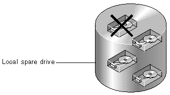
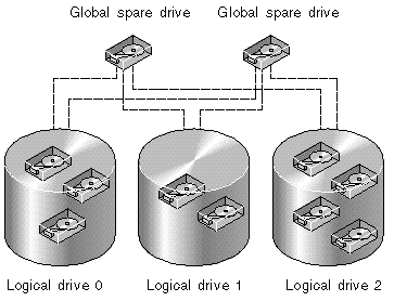
The external RAID controllers provide both local spare drive and global spare drive functions. A local spare drive is used only for one specified logical drive; a global spare drive can be used for any logical drive on the array.
A local spare drive always has higher priority than the global spare drive. Therefore, if a drive fails and global and local spares of sufficient capacity are both available, the local spare is used.
If a drive fails in a RAID 5 logical drive, replace the failed drive with a new drive to keep the logical drive working. To identify a failed drive, see Identifying a Failed Drive for Replacement.

|
Caution - If you mistakenly remove the wrong drive, you will no longer be able to access the logical drive because you have incorrectly failed two drives. |
A local spare drive is a standby drive assigned to serve one specified logical drive. If a member drive of this specified logical drive fails, the local spare drive becomes a member drive and automatically starts to rebuild.

A global spare drive is available to support all logical drives. If a member drive in any logical drive fails, the global spare drive joins that logical drive and automatically starts to rebuild.

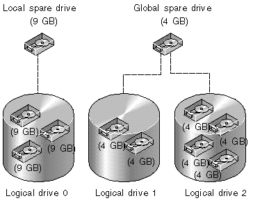
In FIGURE 1-3, the member drives in logical drive 0 are 9-Gbyte drives, and the members in logical drives 1 and 2 are all 4-Gbyte drives.
A local spare drive always has higher priority than a global spare drive. If a drive fails and a local spare and a global spare drive of sufficient capacity are both available, the local spare drive is used.

In FIGURE 1-3, it is not possible for the 4-Gbyte global spare drive to join logical drive 0 because of its insufficient capacity. The 9-Gbyte local spare drive is used for logical drive 0 once a drive in this logical drive fails. If the failed drive is in logical drive 1 or 2, the 4-Gbyte global spare drive is used automatically.
You can access the controller firmware by connecting an RS-232 port on your host to an RS-232 port on your RAID controller with the null-modem cable supplied with your array. The "Connecting Your Array" chapter of the Installation, Operation, and Service Manual for your array contains instructions for setting up communications once this connection is made. Platform-specific instructions are found in the appendix that is appropriate for your hardware and operating system.
You can also access the controller firmware through telnet sessions. The default TCP/IP connection method is to use the IP address, gateway, and netmask assigned by a Dynamic Host Configuration Protocol (DHCP) server. If your network has a DHCP server, you can access the controller's Ethernet port using that IP address without having to set up the RS-232 port connection described above. The "Connecting Your Array" chapter of the Installation, Operation, and Service Manual for your array contains a full description of the various in-band and out-of-band connections available to you.
To access the array using the Ethernet port, the controller must have an IP address. The default setting uses the Dynamic Host Configuration Protocol (DHCP) to automatically assign an IP address if you have a DHCP server on your network and DHCP support is enabled.
You can set the IP address by typing in values for the IP address itself, the subnet mask, and the IP address of the gateway manually.
If your network is using a Reverse Address Resolution Protocol (RARP) server or a Dynamic Host Configuration Protocol (DHCP) server to automatically configure IP information for devices on the network, you can specify the appropriate protocol instead of typing in the information manually.
|
Note - If you assign an IP address to an array to manage it out-of-band, for security reasons consider using an IP address on a private network rather than a publicly routable network. Using the controller firmware to set a password for the controller limits unauthorized access to the array. Changing the firmware's Network Protocol Support settings can provide further security by disabling the ability to remotely connect to the array using individual protocols such as HTTP, HTTPS, telnet, FTP, and SSH. See Communication Parameters for more information. |
|
To set the IP address, subnet mask, and gateway addresses of the RAID controller, perform the following steps:
1. Access the array through the COM port on the controller module of the array.
Refer to the "Connecting Your Array" chapter of the Installation, Operation, and Service manual for your array for information about the communication parameters to use to ensure communication. Refer to the "Configuring a Sun Server Running the Solaris Operating System" appendix in the same document if you want to configure a tip session to use the COM port.
2. Choose "view and edit Configuration parameter  Communication Parameters
  Internet Protocol (TCP/IP)."
3. Select the chip hardware address.
4. Choose "Set IP Address  Address."
5. Configure the Ethernet port.
6. If you are manually configuring the LAN port's IP address:
a. Type an IP address in the text box and press Return
c. Type the correct netmask for the port in the text box and press Return.
e. Type the correct gateway IP address for the port and press Return.
A confirmation prompt is displayed.
8. Select Yes to change the address, or No to leave the existing address.
A confirmation prompt informs you that a controller reset is necessary for the new IP address to take effect and asks if you want to reset the controller now.
9. Select Yes to reset the controller.
Copyright © 2009, Dot Hill Systems Corporation. All rights reserved.