| Skip Navigation Links | |
| Exit Print View | |

|
Sun Blade 6000 Virtualized Multi-Fabric 10GbE M2 Network Express Module User's Guide Sun Blade 6000 Virtualized Multi-Fabric 10GbE M2 Network Express Module Documentation Library |
| Skip Navigation Links | |
| Exit Print View | |

|
Sun Blade 6000 Virtualized Multi-Fabric 10GbE M2 Network Express Module User's Guide Sun Blade 6000 Virtualized Multi-Fabric 10GbE M2 Network Express Module Documentation Library |
About This Documentation (PDF and HTML)
Overview of Sun Blade 6000 Virtualized Multi-Fabric 10GbE M2 NEM User's Guide
Features of the Sun Blade 6000 Virtualized Multi-Fabric 10GbE M2 NEM
Performing Hot Plug Insertion and Removal
Installing or Replacing the Virtualized M2 NEM
Installing and Removing SFP+ Optical Transceiver Modules
Booting Over the Virtualized M2 NEM 10-Gigabit Ethernet Port
Booting over the Network With an x86 Blade Server
Booting over the Network With a SPARC Blade Server
Installing and Configuring the hxge Driver on a Solaris SPARC or x86 Platform
How to Configure the Network Host Files
Configuring the hxge Device Driver Parameters
Configuring the Jumbo Frames Feature
Installing and Configuring the hxge Driver on a Linux Platform
Installing and Removing the Driver on a Linux Platform
Configuring the Network Interface
Checking and Testing the hxge Device
Changing the hxge Driver Configuration
Installing and Configuring Drivers on a Windows Platform
Installing Drivers on a Windows Platform
Installing and Configuring Drivers on a VMware ESX Server Platform
Installing the ESX Server Drivers on an Existing ESX Server
Installing the ESX Server Drivers With a New ESX Installation
Configuring the Virtual NEM M2 Network Adapters
Accessing ILOM Documentation and Updates
Enabling Private and Failover Mode
You can insert either one or two Virtualized M2 NEMs in the Sun Blade 6000 chassis. If you insert only one, install it in the lower slot (NEM 0).
Before installing your NEM, remove the NEM filler panel in the slot you plan to use.
Note - The Virtualized M2 NEM can be paired with a pass-through Gigabit Ethernet NEM or another Virtualized M2 NEM only. Mixing of Multi-Fabric NEM M2 types is not supported.
This procedure is for installing a NEM into an empty slot. If you are replacing a NEM, see Replacing a NEM.
Before You Begin
If you are installing a NEM into a powered on chassis, read Performing Hot Plug Insertion and Removal before installing the NEM.
Ensure that:
The RJ-45 port connectors of the NEM are facing you.
The NEM ejector levers are fully opened.
The NEM ejector levers are on the top of the module.
Support the weight of the NEM with one hand at the bottom of the NEM.
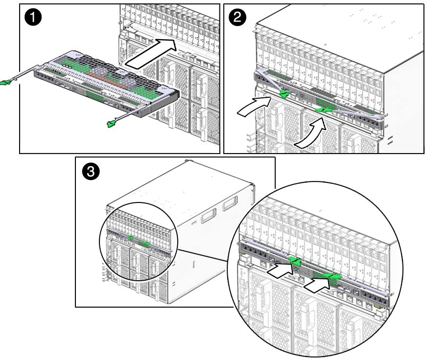
The following illustration shows how to install the NEM.

Standby blink indicates that the NEM is in standby mode.
See Using Hot Plug Commands for information on how to use the ILOM Return to Service command.
It can take up to 3 minutes for the NEM to come online and become fully operational.
Note - If you push the ATTN button twice within 5 seconds, the green Power/OK LED remains in standby blink mode, and the request for bringing the NEM online is cancelled.
The NEM is online and the PCIe interfaces are available to the blades when the following occurs:
The NEM green Power/OK LED illuminates solid.
In the ILOM web interface System Information —> Components screen: The Prepare to Remove option is available in the Actions drop-down list for the NEM.
In the ILOM CLI show /CH/NEMx output, the following status shows in the Properties section: prepare_to_remove_status = NotReady.