Exit Print View

Sun Datacenter InfiniBand Switch 72 Topic Set

Get PDF Book Print View
 

Document Information

Using This Documentation

Related Documentation

Documentation, Support, and Training

Documentation Feedback

User Guide

Installing the Switch

Administering the Switch

Servicing the Switch

Understanding Service Procedures

Replaceable Components

Servicing the Power Supplies

Inspecting a Power Supply

Identify the Power Supply

Inspect the Power Supply Hardware

Inspect the Power Supply Connectors

Power Off a Power Supply

Remove a Power Supply

Install a Power Supply

Power On a Power Supply

Servicing the Fans

Inspecting a Fan

Identify the Fan

Inspect the Fan Hardware

Inspect the Fan Connector

Remove a Fan

Install a Fan

Servicing the InfiniBand Cables

Inspecting an InfiniBand Cable

Identify the InfiniBand Cable

Inspect the InfiniBand Cable Hardware

Inspect the InfiniBand Cable Connectors

Remove an InfiniBand Cable

Install an InfiniBand Cable

Servicing the Battery

Remove the Switch From the Rack

Replace the Battery

Upgrading the Firmware

Reference

Understanding the Commands

Index

Install an InfiniBand Cable

  1. Identify the prerequisite and subsequent service tasks you must perform in conjunction with this procedure.

    See Servicing the InfiniBand Cables.

  2. Determine your next steps:

    • If you are cabling an entire switch after a replacement procedure, locate the cable for the connector 11B and go to Step 5.

    • If you are installing a replacement cable to the switch, start the procedure at Step 3.

  3. Inspect the replacement InfiniBand cable.

    See Inspecting an InfiniBand Cable.

  4. Bring the replacement cable to the switch.

  5. Feed the cable through the cable management hardware.

  6. Orient the cable connector to the CXP receptacle squarely and horizontally.

    Ensure that the upper shell just touches the underside of the top of the receptacle on the rear panel.
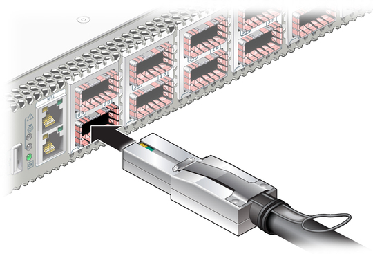

    Illustration shows the InfiniBand cable being attached.
  7. Slowly move the connector in.

    As you slide the connector in, the top of the shell should scrape against the underside of the top of the CXP receptacle.
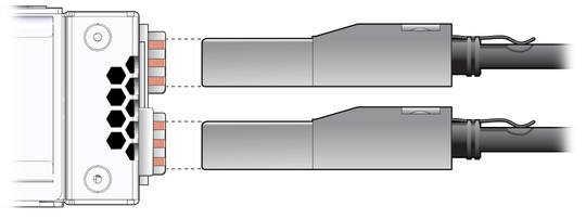

    Illustration shows the InfiniBand cable with proper alignment.
    • If the connector stops or binds after about 1/4 in. (5 mm) travel, back out and repeat from Step 6.

    • If the connector stops or binds with about 1/8 in. (2 mm) still to go, back out and repeat Step 7.

  8. Continue to push the connector in until the hooks catch onto the top of the receptacle.

  9. Secure the cable into the cable management hardware.

    Close hook-and-loop fasteners at bundles and securing hard points.

  10. If you are installing all cables as part of a switch replacement procedure, repeat from Step 5 for all cables, working your way from right to left.

  11. Replace the cover for the cable management bracket and tighten the thumbscrews.
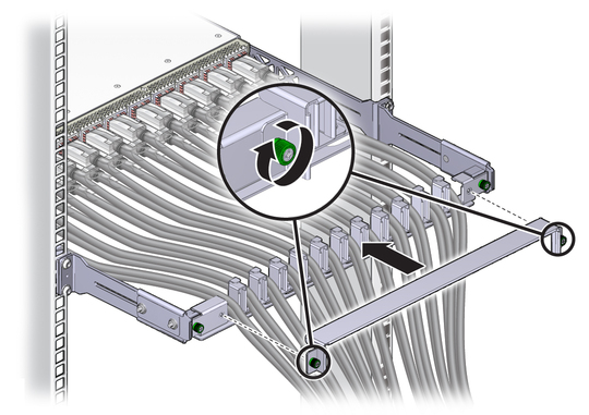

    Illustration shows the cable management bracket cover being installed.
Related Information