Sun Blade 6000 Virtualized
Multi-Fabric 10GbE Network Express Module User’s Guide 6000 Virtualized
Multi-Fabric 10GbE Network Express Module User’s Guide |
| C H A P T E R 2 |
This chapter describes how to replace a Sun Blade 6000 Virtualized Multi-Fabric 10GbE Network Express Module (Virtualized NEM) in a powered-on Sun Blade 6000 Series Chassis. This chapter also includes instructions to verify that the replacement Virtualized NEM has been installed correctly.
This chapter contains the following sections:
You can insert either one or two Virtualized Multi-Fabric 10GbE NEMs in the Sun Blade 6000 chassis. If you insert only one, it should go in the lower slot (NEM 0).
Before installing your NEM, remove the NEM filler panel in the slot you plan to use.
Note - The Virtualized NEM can be paired with a pass-through Gigabit Ethernet NEM or another Virtualized NEM only. Mixing of Multi-Fabric NEM types is not supported. |
This procedure is for installing a NEM into an empty slot. If you are replacing a NEM, see Replacing a NEM.
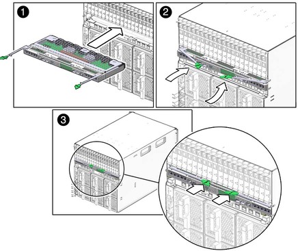
Slide the NEM into the vacant NEM chassis slot until you feel it stop.
Support the weight of the NEM with one hand at the bottom of the NEM.
Complete the installation by closing the ejector levers to secure the NEM in the chassis.
FIGURE 2-1 shows how to install the NEM.
Refer to the chassis documentation for information on powering on the chassis.
Execute the procedure Saving a Snapshot of Your Host Bus Adapter Persistence Mappings on all server blades in the chassis that meet all three of these requirements:
Connect cables, as needed. See Cabling the SPF+ Connectors.
The following topics are covered in this section:
In a web browser, type the IP address of the CMM in the location bar.
Select Components from the second row of tabs (FIGURE 2-2).
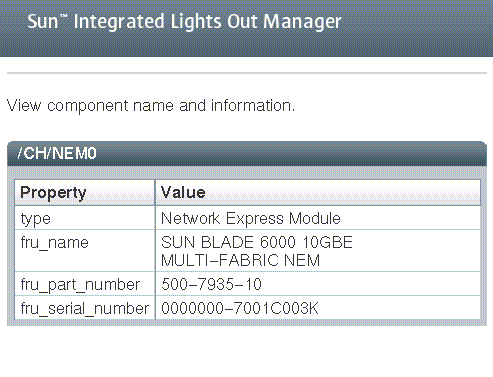
Select /CH/NEM0 (FIGURE 2-3).
If the NEM does not appear in ILOM, verify that the NEM is properly seated in the chassis.
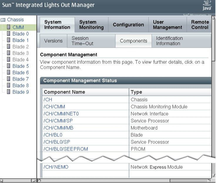
The NEM is automatically detected when the chassis is powered on.
You can connect to the ILOM CLI by either of two methods:
Connect a terminal or PC running a terminal emulator directly to the CMM serial port on your chassis.
Connect to the chassis Ethernet network management port using a secure shell (SSH).
Instructions for setting up and using ILOM are documented in Appendix B.
Note - The examples in this section refer to NEM0. If you are installing NEM1, replace the “0” in these examples with “1”. |
The NEM and the NEM Field Replaceable Unit (FRU) information appears in the CLI.
-> show /CH/NEM0 Targets: SEEPROM SP Properties: type = Network Express Module fru_name = SUN BLADE 6000 10GBE Hydra NEM fru_part_number = 501-7935-02 fru_serial_number = 0000000-7001C003K Commands: cd show |
If the NEM does not appear in ILOM, verify that the NEM is properly seated in the chassis and verify that you have installed the latest CMM ILOM firmware.
For more information about using CMM ILOM, see the your ILOM documentation, at: (http://docs.sun.com/app/docs/prod/blade.6000mod#hic)
This procedure is for removing a NEM if you do not plan to replace it. If you plan to replace a NEM, see Replacing a NEM.
In the rear of the chassis, locate the NEM that you want to remove.
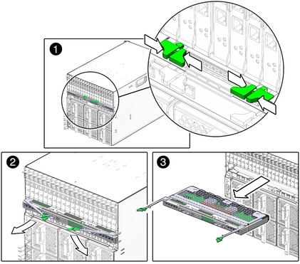
Press together and hold the buttons on both the right and left ejector levers.
To unlatch the NEM from the chassis, open the ejector levers by extending them outward.
Holding the open ejector levers, pull the NEM toward you until you can pull the rest of the module out by hand.
Support the weight of the NEM with one hand at the bottom of the NEM.
FIGURE 2-4 shows how to remove a NEM.
If a NEM fails, you need to replace it. You must power off the chassis before you remove the NEM. The server modules must be informed if you are replacing a non-redundant NEM.
 | Caution - If the chassis is powered on and you are not replacing the NEM within 60 seconds, install an NEM filler panel to ensure proper system operation. |
In the rear of the chassis, locate the NEM that you want to remove.
Label the cables so that you can install them in the same location, then remove all cables from the NEM.
Press together and hold the buttons on both the right and left ejector levers.
To unlatch the NEM from the chassis, open the ejector levers by extending them outward.
Holding the open ejector levers, pull the NEM toward you until you can pull the rest of the module out by hand.
Support the weight of the NEM with one hand at the bottom of the NEM.
FIGURE 2-4 shows how to remove a NEM.
Determine if the following are present in the chassis:
If both of the above conditions are true, continue with Step 10. If either one of the above conditions is not true, continue to Step 13.
Follow the procedure Using the Interactive lsiutil Menus to Clear Your LSI Host Bus Adapter Non-Present Persistence Mapping on all server blades in the chassis that meet both of these requirements listed in Step 7.
Execute the procedure Saving a Snapshot of Your Host Bus Adapter Persistence Mappings on all server blades in the chassis that meet all three of these requirements:
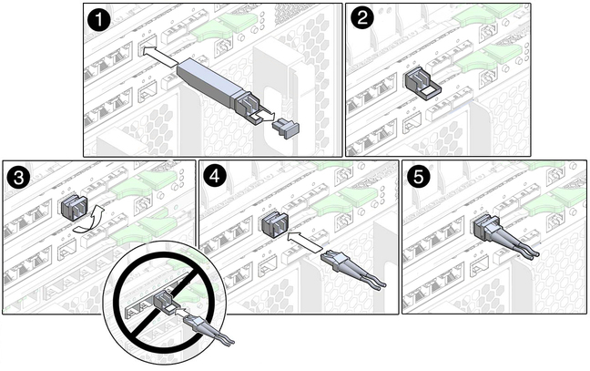
The NEM requires an SFP+ transceiver in at least one port to create a 10GbE connection. Before installing or removing an SFP+ module, refer to Connectivity Mode.
Pull the locking handle into the full horizontal position until you feel the handle click into position.
Holding the optical transceiver (SFP+ module) by the edges, align the SFP+ module with the slot in the NEM and slide it into the opening.
Applying even pressure at both corners of the SFP+ module, push the module until it is firmly seated in the slot.
Push the handle closed to lock the SFP+ module in place.
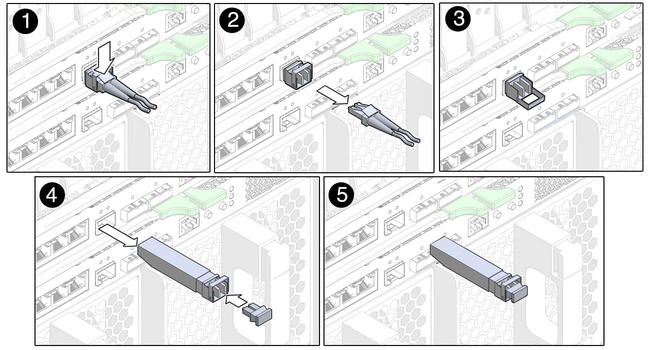
Press the optical cable connector latch down and gently pull out the optical cable (FIGURE 2-6).
Replace the protective end caps if you plan to store the module.
The following table shows the optical module (OM) multimode fiber (MMF) and single-mode fiber (SMF) cabling options available for the Virtualized Multi-Fabric 10GbE NEM SPF+ connectors.
| SPF+ Connector Type | Cable type | Reach |
|---|---|---|
| Short range (SR) | OM 1 MMF | 33 meters |
| OM 2 MMF | 50 meters | |
| OM 3 MMF | 300 meters |
Note - The optical transceiver for the Virtualized Multi-Fabric 10GbE NEM uses a long connector (LC). The connection on the other side of the cable might use a different connector type. |
 | Caution - Avoid putting unnecessary stress on the connection. Do not bend or twist the cable near the connectors, and avoid sharp cable bends of more than 90 degrees. |
Copyright © 2009, Sun Microsystems, Inc. All rights reserved.