| Skip Navigation Links | |
| Exit Print View | |

|
Sun Fire X4470 Server Service Manual |
1. Sun Fire X4470 Server Service Manual Overview
1.1.1 Intel Xeon 7500 Platform
1.1.7 Summary of Supported Components and Capabilities
1.2 Server Front Panel Features
1.3 Server Back Panel Features
1.4 Performing Service Related Tasks
2. Preparing to Service the Sun Fire X4470 Server
2.1 Location of Replaceable Components
2.2 Tools and Equipment Needed
2.3 Performing Electrostatic Discharge and Static Prevention Measures
2.3.1 Using an Antistatic Wrist Strap
2.4 Positioning the Server for Maintenance
Extend the Server to the Maintenance Position
2.5 Releasing the Cable Management Arm
Power Off the Server Using the Service Processor Command-Line Interface
2.7 Removing the Server Top Cover
2.8 Removing or Installing Filler Panels
2.9 Attaching Devices to the Server
3. Servicing CRU Components That Do Not Require Server Power Off
3.1 Servicing Disk Drives (CRU)
3.1.1 Disk Drive Status LED Reference
3.1.2 Removing and Installing Disk Drives and Disk Drive Filler Panels
Remove a Disk Drive Filler Panel
Install a Disk Drive Filler Panel
3.2 Servicing Fan Modules (CRU)
3.2.2 Fan Module LED Reference
3.2.3 Detecting Fan Module Failure
3.2.4 Removing and Installing Fan Modules
3.3 Servicing Power Supplies (CRU)
3.3.1 Power Supply LED Reference
3.3.2 Detecting a Power Supply Failure
3.3.3 Removing and Installing Power Supplies
4. Servicing CRU Components That Require Server Power Off
4.1 Servicing Memory Risers and DIMMs (CRU)
4.1.1 CPUs, Memory Risers, and DIMMs Physical Layout
4.1.2 Memory Riser Population Rules
4.1.3 Memory Riser DIMM Population Rules
4.1.4 Memory Performance Guidelines
4.1.7 Removing and Installing Memory Risers, DIMMs, and Filler Panels
Remove a Memory Riser Filler Panel
Remove a Memory Riser and DIMM
Install Memory Risers and DIMMs
Install a Memory Riser Filler Panel
4.2 Servicing PCIe Cards (CRU)
4.2.1 PCIe Card Configuration Rules
4.2.2 PCIe Cards With Bootable Devices
4.2.3 Avoiding PCI Resource Exhaustion Errors
4.2.4 Removing and Installing PCIe Cards and PCIe Card Filler Panels
Remove a PCIe Card Filler Panel
Install a PCIe Card Filler Panel
4.3 Servicing the DVD Drive and DVD Driver Filler Panel (CRU)
Remove the DVD Drive or DVD Drive Filler Panel
Install the DVD Drive or DVD Drive Filler Panel
4.4 Servicing the System Lithium Battery (CRU)
5.1 Servicing the CPU and Heatsink (FRU)
5.1.2 Removing and Installing a Heatsink Filler Panel, CPU Cover Plate, Heatsink, and CPU
5.2 Servicing the Fan Board (FRU)
5.3 Servicing the Power Supply Backplane (FRU)
Remove the Power Supply Backplane
Install the Power Supply Backplane
5.4 Servicing the Disk Drive Backplane (FRU)
Remove the Disk Drive Backplane
Install the Disk Drive Backplane
5.5 Servicing the Motherboard (FRU)
6. Returning the Server to Operation
6.1 Replacing the Server Top Cover
6.2 Returning the Server to the Normal Rack Position
Return the Server to the Normal Rack Position
7. Servicing the Server at Boot Time
7.3 Default BIOS Power-On Self-Test (POST) Events
7.4 BIOS POST F1 and F2 Errors
7.5 How BIOS POST Memory Testing Works
7.6 Ethernet Port Device and Driver Naming
7.6.1 Ethernet Port Booting Priority
7.8 Performing Common BIOS Procedures
7.8.1 Configuring Serial Port Sharing
8. Troubleshooting the Server and Oracle ILOM Defaults
8.1 Troubleshooting the Server
8.2.1 Diagnostic Tool Documentation
8.3 Using the Preboot Menu Utility
8.3.1 Accessing the Preboot Menu
8.3.2 Restoring Oracle ILOM to Default Settings
8.3.3 Restoring Oracle ILOM Access to the Serial Console
8.3.4 Restoring the SP Firmware Image
8.3.5 Preboot Menu Command Summary
8.5 Locating the Chassis Serial Number
A.3 Environmental Requirements
B.2 BIOS Advanced Menu Selections
B.3 BIOS PCIPnP Menu Selections
B.5 BIOS Security Menu Selections
B.6 BIOS I/O MMIO Menu Selections
B.7 BIOS Chipset Menu Selections
C.3 Gigabit-Ethernet Connectors
C.4 Network Management Port Connector
This section includes instructions for performing some common procedures using the BIOS Setup Utility.
To access the BIOS Setup Utility, complete the following steps:
Note - If there is an error during the boot process, you can press F1 to access the BIOS Setup Utility.
Alternatively, you can use the following hot key combinations to access the BIOS Setup Utility from a serial connection:
F1 Control-Q
F2 Control-E.
F7 Control-D
F8 Control-P
F9 Control-O
F10 Control-S
F12 Control-N
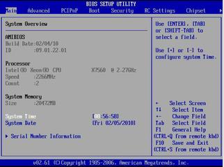
The BIOS Setup Utility Main screen appears (BIOS Setup Utility Main Screen).
Figure 7-4 BIOS Setup Utility Main Screen
To reset the BIOS password, complete the following steps:
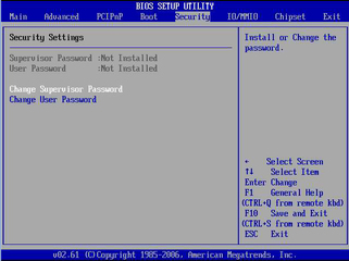
The Security screen appears (BIOS Security Screen).
Figure 7-5 BIOS Security Screen
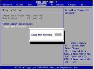
The Enter New Password dialog box appears (Enter New Password Dialog Box).
Figure 7-6 Enter New Password Dialog Box
If you intend to use the Trusted Platform Module (TPM) feature set that is provided in Windows Server 2008, you must configure the Sun Fire X4470 Server to enable this feature.
Note - TPM enables you to administer the TPM security hardware in your server. For additional information about implementing this feature, refer to the Windows Trusted Platform Module Management documentation provided by Microsoft.
To configure the server to support TPM, complete the following steps:
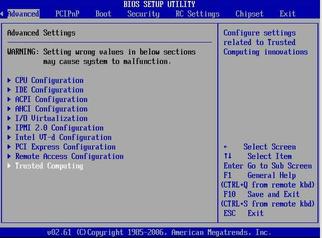
The BIOS Advanced Settings screen appears (BIOS Advanced Settings Screen).
Figure 7-7 BIOS Advanced Settings Screen
The Trusted Computing screen appears (Trusted Computing Screen).
Figure 7-8 Trusted Computing Screen

A screen appears listing the available TCG/TPM options (TCG/TPM Support Screen).
Figure 7-9 TCG/TPM Support Screen
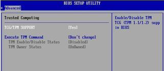
Note - If the TCG/TPM Support option is already set to Yes, you should still complete the remaining steps in this procedure to ensure that all TPM configuration requirements are satisfied.
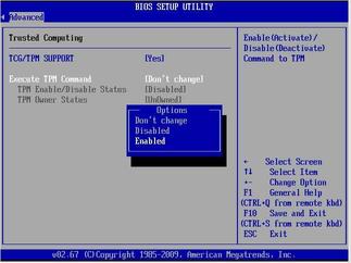
Note - The Execute TPM Command setting is set to [Don’t Change] by default.
Figure 7-10 Setting Execute TPM Command Option to Enabled
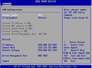
You can assign an IP address for the server SP from the BIOS Setup Utility on the IPMI 2.0 Configuration menu.
Note - You can also specify the LAN settings for the SP using Oracle ILOM. For instructions for setting the IP address in Oracle ILOM, see the Oracle Integrated Lights Out Manager (ILOM) 3.0 Documentation Collection.
To set the IP address, complete the following steps:
Figure 7-11 IPMI 2.0 Configuration Selection in Advanced Settings Menu
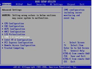
Figure 7-12 Set LAN Configuration Option
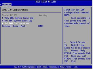
Figure 7-13 LAN Configuration Dialog Box
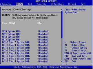
The BIOS Option ROM is 128 Kbytes. Of these 128 Kbytes, approximately 80 Kbytes are used by the VGA controller, the disk controller, and the network interface card. Approximately 48 Kbytes remain for the Option ROM.
To enable or disable Option ROM settings, complete the following steps:
The BIOS PCIPnP screen appears (BIOS PCIPnP Screen).
Figure 7-14 BIOS PCIPnP Screen
By default, the SP console (NET MGT) port sends serial port output from the server. Using Oracle ILOM, you can specify that the host console (COMM1) be assigned as owner of the server’s serial port output. This feature is useful for Windows kernel debugging, as it enables you to view non-ASCII character traffic from the host console.
You can assign serial port output using either the Oracle ILOM web interface or the Oracle ILOM command-line interface (CLI). For instructions, see the following sections:
Assign Serial Port Output Using the Web Interface
 | Caution - You should set up the network on the SP before attempting to change the serial port owner to the host server. If the network is not set up, and you switch the serial port owner to the host server, you will be unable to connect using the CLI or web interface to change the serial port owner back to the SP. To return the serial port owner setting to the SP, you will need to restore access to the serial port on the server. For more details about restoring access to the server port on your server, see the Oracle Integrated Lights Out Manager (ILOM) 3.0 Documentation Collection. |
-> set /SP/serial/portsharing /owner=host
Note - The serial port sharing value by default is owner=SP.
The Serial Port Settings page appears.
Note - The serial port sharing setting by default is Service Processor.