| Skip Navigation Links | |
| Exit Print View | |

|
Sun Blade X6275 M2 Server Module Service Manual |
About This Documentation (PDF and HTML)
Server Module and Components Overview
About the Sun Blade 6000 Modular System Chassis
Powering On and Off the Server Module
Preparation Procedures for Service and Operation
Preparing the Server for Service
How to Prepare the Server Module for Service
Performing ESD and Antistatic Prevention Measures
Using an Antistatic Wrist Strap
How to Setup for ESD prevention
Using the Locate LED to Find the Server Module (Optional)
How to Use the ILOM Web Interface to Turn On and Off the Locate LED
How to Use the ILOM CLI to Turn On and Off the Locate LED
How to Remove the Server Module Top Cover
Preparing the Server for Operation
Component Removal and Installation Procedures
Removing and Installing Flash Modules
Removing and Installing the Energy Storage Modules
Removing and Installing the Service Processor Board
Removing and Installing USB Flash Drives
Removing and Installing a CPU and Heatsink Assembly
How to Replace the Motherboard Assembly
Diagnostic and Maintenance Information and Procedures
Diagnosing Server Module Hardware Faults
BIOS Power-On Self-Test (POST) Codes
Server Module Maintenance Procedures and Information
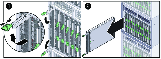
Use this procedure to safely remove the server module from the chassis.
 | Caution - Do not install a server module into the chassis until at least 20 seconds has elapsed since the server module was disengaged from the chassis mid-plane connector. |
Before You Begin
See Preparing the Server for Service.
For information about power modes, see Power Modes.
 | Caution - Possible component damage or personal injury. Do not attempt to remove the server module using only the ejector levers. |

 | Caution - Possible system and component over-temperature warnings, shutdown, and heat-related damage. Do not operate the system with empty slots. Always insert a server module filler panel into an empty slot within 60 seconds to reduce the possibility of server module shutdown. |
Next Steps