| C H A P T E R 5 |
|
Powering On the Array |
This chapter describes initial tray power-on procedures in the following sections:
Decide on an IP address method before powering on.
The controller tray and the expansion tray can have either standard power connections to an AC power source or the optional connections to a DC power source (-48 VDC).
| Note - Do not turn on the power to the controller tray or the connected expansion trays until this documentation instructs you to do so. For the correct procedure for turning on the power, see Powering On the Array. |
1. Make sure that the circuit breakers in the cabinet are turned off.
2. Make sure that both of the Power switches on the expansion trays are turned off.
3. Connect the primary power cords from the cabinet to the external power source.
4. Connect a cabinet interconnect power cord (or power cords specific to your particular cabinet) to the AC power connector on each power module in the expansion tray.
5. If you are installing other expansion trays in the cabinet, connect a power cord to each power module in the expansion trays.
If your expansion tray has the DC power option installed, review the following information.


|
Caution - Risk of bodily injury--A qualified service person is required to make the DC power connection according to NEC and CEC guidelines. |
| Note - Do not turn on power to the expansion tray until this guide instructs you to do so. For the proper procedure for turning on the power, see Powering On the Array. |
1. Disconnect the two-pole, 20-amp circuit breaker for the storage array.
2. Make sure that all of the DC power switches on the DC-powered expansion tray are turned off.
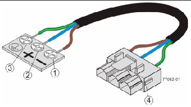
3. Connect the DC power connector cables to the DC power connectors on the rear of the controller tray or controller tray, and expansion trays.
| Note - The three source wires on the DC power connector cable (-48 VDC) connect the expansion tray to centralized DC power plant equipment, typically through a bus bar located above the cabinet. |
4. Have a qualified service person connect the other end of the DC power connector cables to the DC power plant equipment as follows:
a. Connect the brown -48 VDC supply wire to the negative terminal.
b. Connect the blue return wire to the positive terminal.
c. Connect the green/yellow ground wire to the ground terminal.
1. Turn on both Power switches on each expansion tray that is attached to the controller tray. Depending on your configuration, it can take several minutes for each expansion tray to complete the power-on process.
While the power is being applied to the trays, the LEDs on the front and the rear of the trays come on and go off intermittently
2. Check the LEDs on the expansion trays to verify that the power was successfully applied to all of the expansion trays. Wait 30 seconds after turning on the power to the expansion trays before turning on the power to the controller tray.
3. Turn on both Power switches on the rear of the controller tray. Depending on your configuration, it can take several minutes for the controller tray to complete the power-on process.
4. Check the LEDs on the front and the rear of the controller tray and the attached expansion trays.
5. If you see any amber LEDs, make a note of their location.
The array rarely needs to be powered off. You remove power only when you plan to physically move the storage array to another location or are adding additional trays to a controller tray.

|
Caution - Before turning off any power switches on a DC-powered expansion tray, you must disconnect the two-pole, 30-amp circuit breaker. |


1. Stop all I/O from the hosts, if connected, to the storage array.
2. Wait approximately two minutes until all disk drive LEDs have stopped flashing.
After the 2-minute period, data residing in cache is written to disk and the battery mechanisms are disengaged.
3. Check the Cache Active LED on the controller to determine if any outstanding cache needs to be written.
If the LED is on, there is still data that needs to be flushed and written to disk.
4. Ensure that the Cache Active LED is no longer flashing before powering off the storage array.
5. Press each power switch at the back of the controller tray to the Off position.
6. Press the power switches at the back of each expansion tray to the Off position.
After you have connected the management host and data hosts, you are ready to install the management host software as described in the Sun Storage Common Array Manager Quick Start Guide or the Sun Storage Common Array Manager Installation and Setup Guide.
© © 2011, Oracle and/or its affiliates. All rights reserved.