| Skip Navigation Links | |
| Exit Print View | |

|
Sun Server X2-8 (formerly Sun Fire X4800 M2) Service Manual Sun Server X2-8 (formerly Sun Fire X4800 M2) Documentation Library |
| Skip Navigation Links | |
| Exit Print View | |

|
Sun Server X2-8 (formerly Sun Fire X4800 M2) Service Manual Sun Server X2-8 (formerly Sun Fire X4800 M2) Documentation Library |
Sun Server X2-8 Service Manual Overview
Controlling Server Power Remotely
Removing and Installing Components
Preparing for Service and Operation
Removal and Installation Procedures
Removing and Installing a Power Supply (CRU)
Removing and Installing a Hard Drive (CRU)
Removing and Installing a Hard Drive Filler
Replacing the Hard Drive Backplane (FRU)
Adding, Removing, and Installing a CMOD (CRU)
How to Add a CPU Module (CMOD) to the Server Using the Upgrade Kit
How to Remove a CPU Module (CMOD)
How to Remove the CPU Module (CMOD) Cover
How to Install the CPU Module (CMOD) Cover
CPU Module (CMOD) Designation and Population Rules
Removing and Installing a CMOD Filler
How to Replace the CMOD Battery (CRU)
Removing and Installing DIMMs (CRU)
Removing and Installing a RAID Expansion Module (CRU)
Removing and Installing a Fabric Expansion Module (CRU)
Replacing a CPU and Heatsink Assembly (FRU)
Removing and Installing a Fan Module (CRU)
Replacing a Fan Module Controller Board (FRU)
Removing and Installing a NEM or a NEM Filler (CRU)
Removing and Installing a PCIe EM (CRU)
Removing and Installing the Service Processor Module (CRU)
Removing and Installing the Multiport Cable
Removing and Installing the Subassembly Module (FRU)
Sun Server X2-8 Service Procedures and Information
Firmware Information and Procedures
How to Access the BIOS Setup Utility
Component LED Locations and Functions
Sun Server X2-8 Specifications
How to Request Physical Media Online
An animation of the procedure to install a CMOD is available. See animation showing CMOD installation.
Before You Begin
See About Sun Server X2-8 CPU Modules and CMOD Filler Modules.
See CMOD Incompatibility Between Versions of Sun Server X2-8.
For slot designations and population rules, see CPU Module (CMOD) Designation and Population Rules.
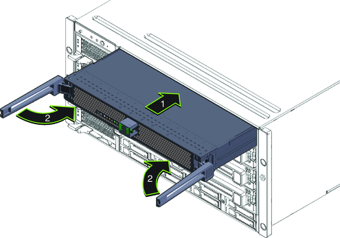
Do not force the module into the chassis in an attempt to engage the connectors on the chassis midplane.
The levers do not extend beyond 90 degrees.
 | Caution - Pinch point. Keep your fingers clear of the back side of the lever, the lever hinges, and the edges of the module. |
This action pushes the module into the chassis and engages the connector on the back of the module with the connector on the interior midplane. When the levers are locked, you cannot rotate the levers outward.

Note - Do not unlock the leversNow therto perform this action.
 | Caution - Pinch point. When operating the lever, keep your fingers clear of the back side of the lever, the lever hinges, and the edges of the module. |
This action pushes the filler module into the chassis. When the handle is locked, you cannot lift the levers without first releasing the lock on the handle.
See Also