Remove the Motherboard Assembly
- Prepare the server for service.
-
Remove the Oracle Storage 12 Gb/s SAS PCIe RAID HBA card and its associated super
capacitor.
See Remove the Oracle Storage 12 Gb/s SAS PCIe RAID HBA Card.
-
Remove the air baffle.
Remove the air baffle by lifting the baffle up and out of the server.
-
Remove the following reusable components:

Caution - During the motherboard removal procedure, it is important to label power supplies with the slot numbers from which they were removed (PS0, PS1). This is required because the power supplies must be reinstalled into the slots from which they were removed; otherwise, the server key identity properties (KIP) data might be lost. When a server requires service, the KIP is used by Oracle to verify that the warranty on the server has not expired. For more information on KIP, see FRU Key Identity Properties (KIP) Automated Update.
-
Fan modules
See Remove a Fan Module.
-
SAS storage drive cables
-
NVMe cables (if present)
See Remove NVMe Cables.
-
PCIe cards
See Remove a PCIe Card.
-
Power supplies
-
-
If the server has a DVD drive, disconnect the DVD drive cable from the
motherboard SATA connector.
To remove the DVD drive cable, carefully guide it through the chassis mid-wall and place it on top of the disk cage so that it is away from the motherboard. You do not need to disconnect the DVD drive cable from the DVD drive.
See Remove the DVD Drive.
-
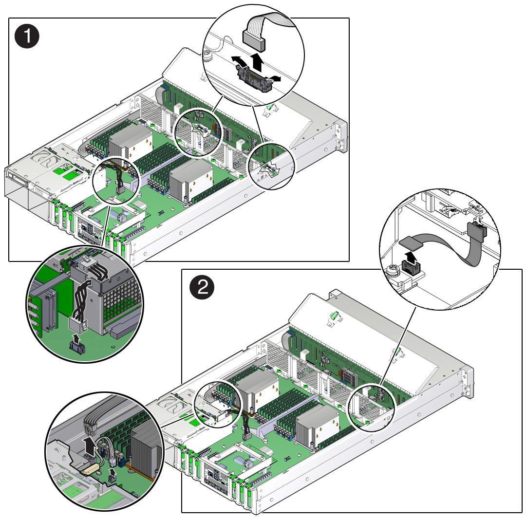
Disconnect the power cable from the motherboard to the rear storage drive
backplane [1].
See Servicing the Front and Rear Storage Drive Backplanes (FRU).
-
Disconnect the ribbon cables from the left front LED indicator module
and right front LED/USB indicator module [1].
See Servicing the Front LED/USB Indicator Modules (FRU).
-
Disconnect the auxiliary signal cable from the motherboard to the front storage
drive backplane [2].
See Servicing the Front and Rear Storage Drive Backplanes (FRU).
-
Disconnect the power cable from the motherboard to the front storage drive
backplane [2].
See Servicing the Front and Rear Storage Drive Backplanes (FRU).
- Disconnect the signal cable from the server intrusion switch [2].
-
Remove the mid-wall from the chassis.
-
Using a hex/flat head screwdriver, remove the screw on each side of the
chassis that secures the mid-wall to the chassis [3].
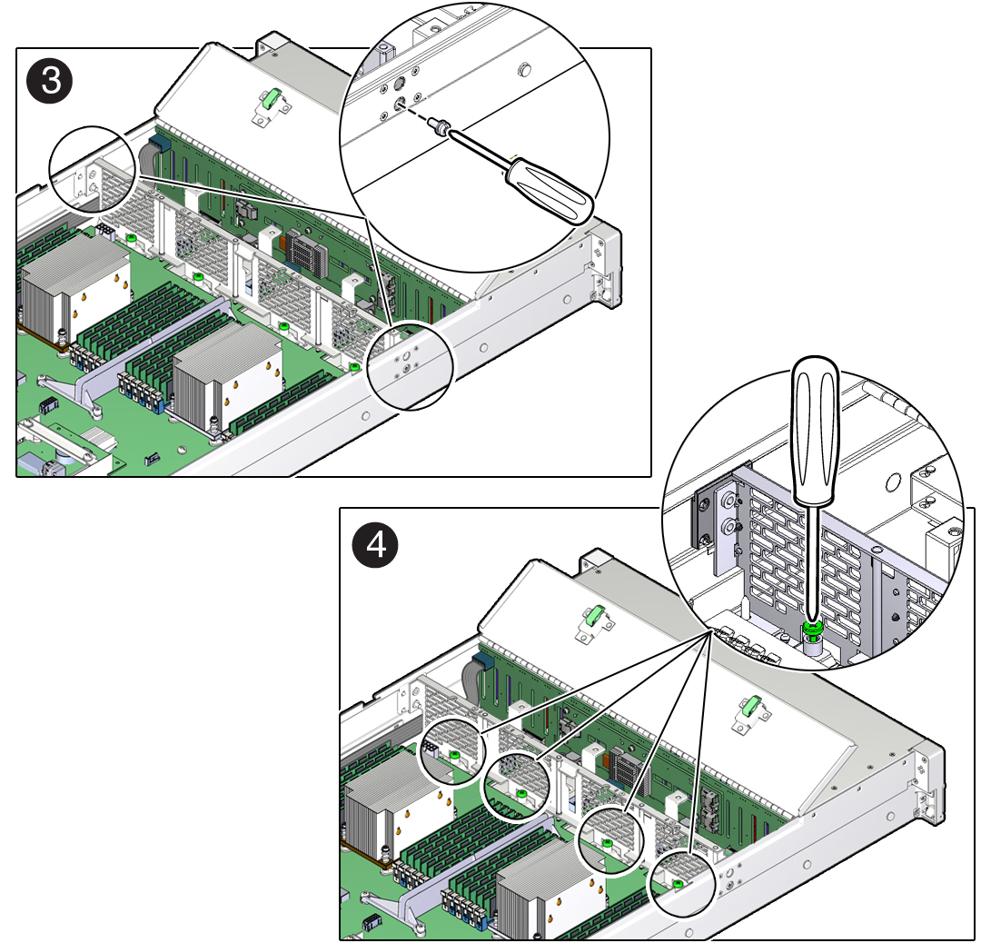
- Using a No. 2 Phillips screwdriver, loosen the four green captive screws that secure the chassis mid-wall to the bottom of the chassis [4].
-
Lift the mid-wall out of the chassis [5].
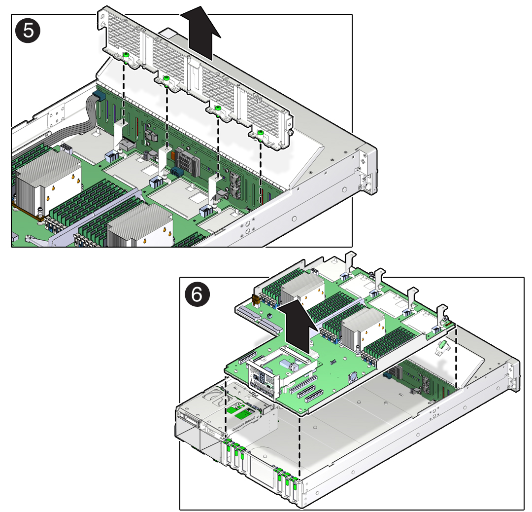
-
Using a hex/flat head screwdriver, remove the screw on each side of the
chassis that secures the mid-wall to the chassis [3].
- With the server in the extended maintenance position, remove the motherboard from the server with all reusable components that populate the motherboard in place.
-
Remove the following reusable components from the motherboard and install them
onto the replacement motherboard.
-
DDR4 DIMMs
See Identify and Remove a Faulty DIMM and Install a DIMM.
Note - Install the DDR4 DIMMs only in the slots (connectors) from which they were removed. Performing a one-to-one replacement of DIMMs significantly reduces the possibility that DIMMs will be installed in the wrong slots. If you do not reinstall the DIMMs in the same slots, server performance might be reduced and some DIMMs might not be used. -
USB flash drives
See Remove an Internal USB Flash Drive and Install an Internal USB Flash Drive.
-
-
Remove the processors from the failed motherboard.
See Remove a Processor.
-
Remove the processor socket covers from the replacement motherboard and install
the processors.
-
Disengage the processor Independent Loading Mechanism (ILM) assembly
hinge lever on the right side of the processor socket (viewing the server
from the front) by pushing down on the lever and moving it to the side away
from the processor, and then rotating the lever upward [1].
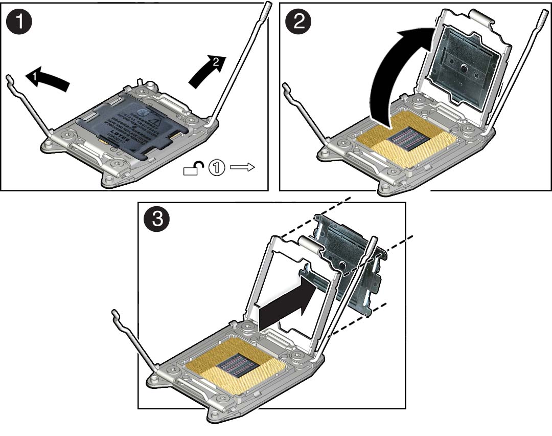
- Disengage the processor ILM assembly load lever on the left side of the processor socket (viewing the server from the front) by pushing down on the lever and moving it to the side away from the processor, and then rotating the lever upward [1].
- To lift the processor ILM assembly load plate off of the processor socket, rotate the ILM assembly hinge lever on the right side of the processor toward the closed position (the load plate is lifted up as the hinge lever is lowered) and carefully swing the load plate to the fully open position [2].
-
Grasp the top and underside of the processor socket cover with one hand
(place your thumb against the underside of the cover), place your other
thumb against the underside of the cover, and carefully push the cover out
of the processor ILM assembly load plate [3].
Caution - Be careful not to allow the processor socket cover to fall into the processor socket as this could result in damage to the socket.
-
Install a processor into the socket from which you removed the processor
socket cover.
See Install a Processor.
- Repeat Step 15.a through Step 15.e to remove the second processor socket cover from the replacement motherboard and install the second processor.
-
Disengage the processor Independent Loading Mechanism (ILM) assembly
hinge lever on the right side of the processor socket (viewing the server
from the front) by pushing down on the lever and moving it to the side away
from the processor, and then rotating the lever upward [1].
-
Install the processor socket covers on the faulty motherboard.
Caution - The processor socket covers must be installed on the faulty motherboard; otherwise, damage might result to the processor sockets during handling and shipping.
Caution - Be careful not to allow the processor socket cover to fall into the processor socket as this could result in damage to the socket.
-
Open one of the processor ILM assemblies on the faulty motherboard [1 and
2].
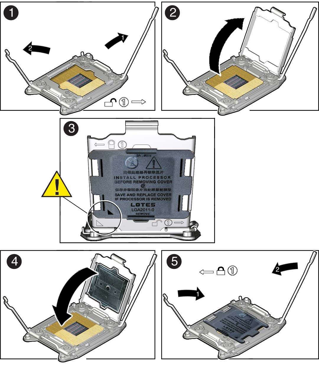
- Hold the processor ILM assembly load plate open with one hand and position the processor socket cover over the top of the pressure frame so that 1) the arrow on the processor socket cover is aligned with the arrow on the load plate and 2) the fasteners on one side of the cover (the fasteners are located on the underside of the cover) are inside the load plate (it does not matter which side), and use your thumb to press the other side of the processor socket cover into the load plate. [3].
- Close the processor ILM assembly load plate [4 and 5].
- Repeat Step 16.a through Step 16.c to install the second processor socket cover on the faulty motherboard.
-
Open one of the processor ILM assemblies on the faulty motherboard [1 and
2].