2 Overview of SOA Component Editors
This chapter provides an overview of all the component editors and designers, which are used to develop an SOA composite application.
This chapter includes the following sections:
2.1 Introduction to the SOA Composite Editor
The SOA Composite Editor enables you to create, edit, and deploy services, and also to assemble them in a composite application, all from a single location. These components are integrated together into one application and communicate with the outside world through binding components such as web services and JCA adapters.
The SOA Composite Editor enables you to use either of two approaches for designing SOA composite applications:
-
The top-down approach of building a composite application puts interfaces first and implementation next. For example, you first add BPEL processes, human tasks, business rules, and mediator routing services components to an application, and later define the specific content of these service components.
-
The bottom-up approach takes existing implementations of service components and wraps them with web service interfaces for assembly into a composite application. For example, you first create and define the specific content of BPEL processes, human tasks, business rules, and mediator routing services components, and later create an SOA composite application to which you add these service components.
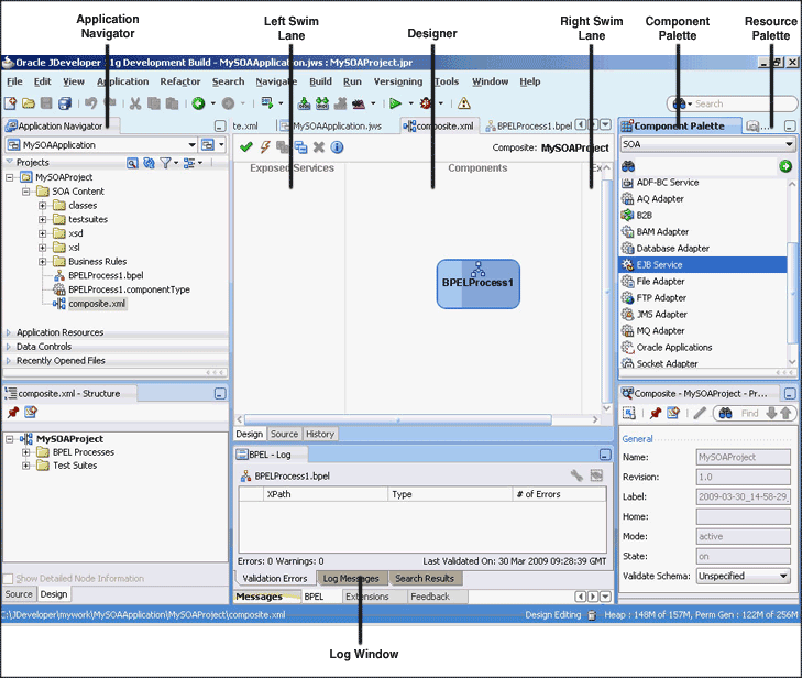
The SOA Composite Editor appears as shown in Figure 2-1.
The main sections of the SOA Composite Editor are described in the following list:
2.1.1 Application Navigator
Displays the key files for the specific service components included in your SOA project:
-
A
composite.xmlfile that is automatically created when you create a SOA project. This file describes the entire composite assembly of services, service components, references, and wires. -
The business rules service component file (
rules_name.decs). Additional business rules files display under the Oracle > rules subfolder (rules_name.rules). -
The mediator service component file (
mediator_name.mplan). -
The BPEL process service component files (
process_name.bpelandprocess_name.wsdl). -
The human task service component files (
task_name.task). -
The
componentTypefile that describes the services and references for each service component. This file ensures that the wiring you create between components works. -
Additional subfolders for class files, XSDs (schemas), and XSLs (transformations).
You can drag and drop components and service adapters from the Components Palette window to the Designer window. When you drop a service component into the Designer window, it starts a property editor for configuring that service component. For example, when you drop a Mediator component into the Designer window, this also opens the Mediator editor window that enables configure the Mediator.
To edit the configuration of an existing component in the Designer window, double-click the component to re-open the editor.
2.1.2 Designer
You drag service components, services, and references into the composite in the designer. When you drag and drop a service component into the Designer window, a corresponding property editor is invoked for performing configuration tasks related to that service component. For example, when you drag and drop the Mediator component into Designer, then the Mediator Editor window is displayed that enables you to configure the Mediator component.
For all subsequent editing sessions, you double-click these service components to invoke their editors.
2.1.3 Left Swim Lane (Exposed Services)
The left swim lane is for services providing an entry point to the SOA composite application, such as a web service or JCA adapters.
2.1.4 Right Swim Lane (External References)
The right swim lane is for references that send messages to external services in the outside world, such as web services and JCA adapters.
2.1.5 Component Palette
Contains the various resources that you can use in a SOA composite. It contains the following service components and adapters:
-
Service components
Displays the BPEL Process, business rule, human task, and mediator service that can be dragged and dropped into the designer.
-
Service adapters
Displays the JCA adapter (AQ, file, FTP, Database, JMS, MQ, Oracle Applications, Oracle BAM, and EJB Service), B2B binding component, SDO binding component, and web service binding component that can be dragged into the left or right swim lanes.
If the Resource Catalog does not display, select Component Palette from the View main menu.
2.1.6 Resource Palette
Provides a single dialog from which you can browse both local and remote resources. For example, you can access.
-
Shared local application metadata such as schemas, WSDLs, event definitions, business rules, and so on.
-
WSIL browser functionality that uses remote resources that can be accessed through an HTTP connection, file URL or Application Server connection.
-
Remote resources that are registered in a UDDI (Universal Description, Discover and Integration) registry.
If the Resource Catalog does not display, then select Resource Palette from the View main menu.
You select these resources for the SOA composite application through the SOA Resource Browser dialog. This dialog is accessible through a variety of methods. For example, when you select the WSDL file to use with a service binding component or a mediator service component or select the schema file to use in a BPEL process, the SOA Resource Browser dialog appears. Click Resource Palette at the top of this dialog to access available resources.
2.1.8 Property Inspector
Displays properties for the selected service component, service, or reference.
If the Property Inspector does not display, select Property Inspector from the View main menu.
For more information about the SOA Composite Editor, see Chapter 4, "Introduction to the Functionality of the SOA Composite Editor" and Oracle Fusion Middleware Getting Started with Oracle SOA Suite.
2.2 Introduction to the Oracle BPEL Designer
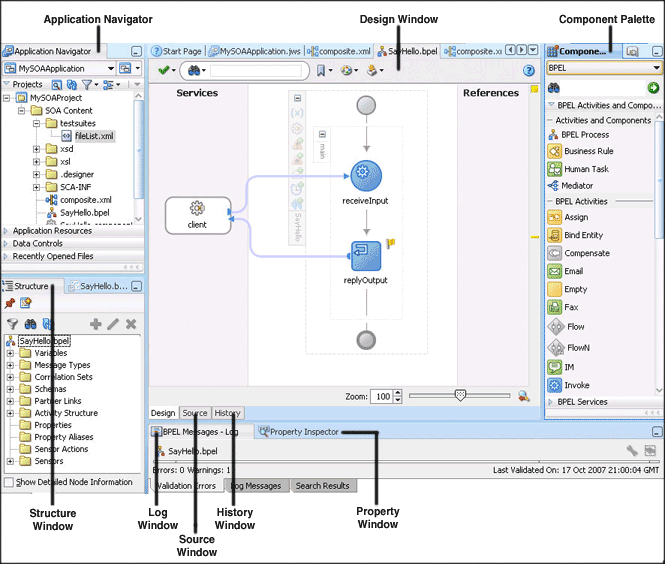
You can create a BPEL process service component in the SOA composite application of Oracle JDeveloper and then design it by using the BPEL Designer, which is displayed, when you double-click a BPEL process in the SOA Composite Editor. Figure 2-2 shows the BPEL Designer along with Application Navigator, Structure, Component Palette, and Messages windows.
Each section of this view enables you to perform specific design and deployment tasks. The main sections of the BPEL Designer are described in the following list:
2.2.1 Application Navigator
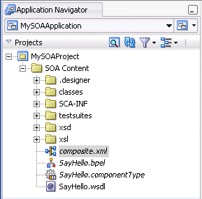
The Application Navigator displays the process files. Figure 2-3 shows the files that appear under the SOA Content folder when you first create a SOA project in Oracle JDeveloper (in this example, named MySOAProject inside an application named MySOAApplication, SayHello is the name of the BPEL process). An application can contain one or more projects. Each project can only contain one composite. But each composite can have multiple components of either the same type or different types (BPEL process, Oracle Mediator, human workflow, and business rules).
Table 2-1 describes these initial process files.
Table 2-1 Initial Process Files
| File | Description |
|---|---|
|
composite.xml |
The file that describes the entire SOA composite. For more information about this file, see Section 2.1, "Introduction to the SOA Composite Editor" |
|
SayHello.bpel |
The source file, which, depending upon the process type you selected, initially contains a minimal set of activities (if you selected to create an asynchronous process, then receive and invoke activities appear). You add syntax to this file when you drag activities, create variables, create partner links, and so on. |
|
SayHello.componentType |
The file that describes the services and references for each service component. |
|
SayHello.wsdl |
The Web Services Description Language (WSDL) client interface, which defines the input and output messages for this BPEL process flow, the supported client interface and operations, and other features. This functionality enables the BPEL process flow to be called as a service. |
As you design the BPEL process service component, additional files, folders, and elements can appear in the Application Navigator.
Note:
If you want to learn more about the Application Navigator, place the cursor in this section and press F1 to display online Help.2.2.2 Design Window
The Design window provides a visual view of the BPEL process service component that you design. This view displays when you perform one of the following actions:
-
Double-click the .bpel file name in the Application Navigator.
-
Double-click the BPEL process component in the SOA Composite Editor.
-
Click the Design tab at the bottom of the window with the .bpel file selected.
Figure 2-4 shows the activities automatically created with an asynchronous BPEL process service component. You add to the BPEL process service component by dragging and dropping activities, creating variables, creating partner links, and so on.
Figure 2-4 Design (After Creation of an Asynchronous BPEL Process Service Component)
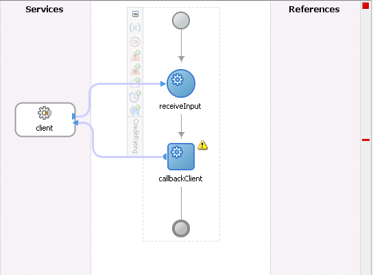
Description of "Figure 2-4 Design (After Creation of an Asynchronous BPEL Process Service Component)"
2.2.3 Source Window
Click Source at the bottom to view the syntax inside the BPEL process service component files. As you drag activities and partner links, and perform other tasks, the Source view and Design view stay synchronized. Changes in one are reflected in the other immediately.
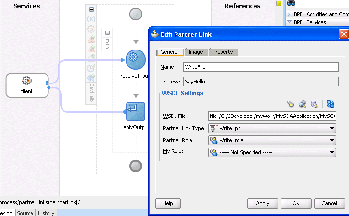
For example, Figure 2-5 shows the property sheet as it is being edited.
Figure 2-5 WriteFile Partner Link Icon and Property Sheet
Description of "Figure 2-5 WriteFile Partner Link Icon and Property Sheet"
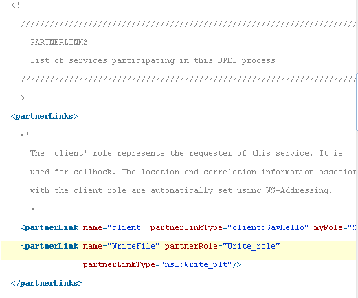
Click Source at the bottom of the window. Figure 2-6 shows part of the Source of a .bpel file. Details about the WriteFile partner link you created appear in the file.
For more information about the types of syntax that appear in BPEL process service component files, see Section 4, "Using the BPEL Process Service Component."
2.2.4 History Window
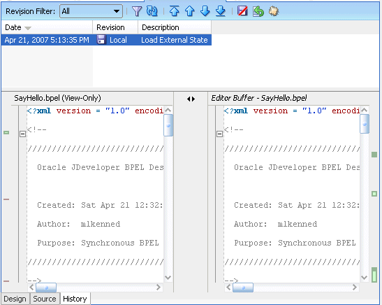
Click History at the bottom to perform such tasks as viewing the revision history of a file and viewing read-only and editable versions of a file side-by-side. Figure 2-7 shows the History view for a BPEL file.
Note:
If you want to learn more about the History view, place the cursor in this section and press F1 to display online Help.2.2.5 Component Palette
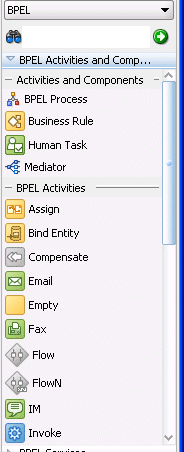
Activities are the building blocks of the BPEL process service component. The BPEL Activities selection of the Component Palette displays a set of activities that you drag into the Design window of the BPEL process service component. The Component Palette is context-aware and only displays those pages relevant to the state of the Design window. BPEL Activities or BPEL Services are nearly always visible. However, if you are designing a transformation in a transform activity, the Component Palette only displays selections relevant to that activity, such as String Functions, Mathematical Functions, and Node-set Functions.
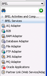
Figure 2-8 shows the BPEL Activities selection of the Component Palette. This list enables you to select activities to drag into your BPEL process service component.
Figure 2-8 Component Palette - BPEL Activities
Description of "Figure 2-8 Component Palette - BPEL Activities"
Figure 2-9 shows the BPEL Services selection of the Component Palette. This list enables you to drag adapters, partner links, or decision services into your BPEL process service component.
Note:
If you want to learn more about the Component Palette, place the cursor in this section and press F1 to display online Help.2.2.6 Property Inspector
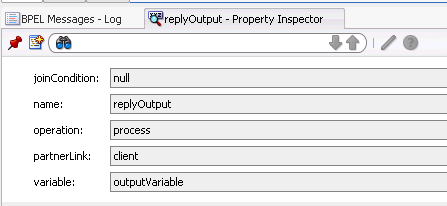
The Property Inspector enables you to view details about an activity. Single-click an activity in the Design window. For example, single-clicking the replyOutput receive activity displays the information shown in Figure 2-10.
2.2.7 Structure Window
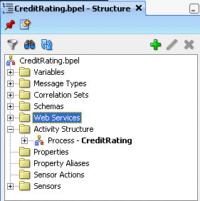
The Structure window offers a structural view of the data in the BPEL process service component currently selected in the Design window. You can perform a variety of tasks from this section, including:
-
Importing schemas
-
Defining message types
-
Managing (creating, editing, and deleting) elements such as variables, aliases, correlation sets, partner links, and sensors
-
Creating activities in the BPEL process flow sequence using the Structure window
Figure 2-11 shows the Structure window.
2.2.8 Log Window
The Log window displays messages about the status of validation and compilation. If deployment is unsuccessful, messages appear that describe the type and location of the error.
Note:
If you want to learn more about the Log window, place the cursor in this section and press F1 to display online Help.For more information about BPEL, refer to Part II, "Using the BPEL Process Service Component".
2.3 Introduction to the Oracle Mediator Editor
You can create a Mediator in the SOA composite application of Oracle JDeveloper and then design it by using the Mediator Editor, which is displayed when you double-click a Mediator in SOA Composite Editor.
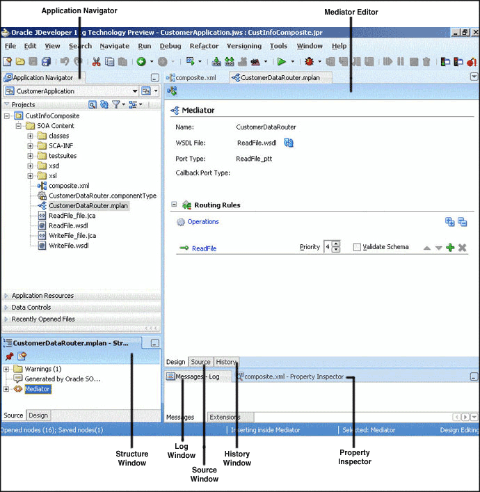
Figure 2-12 shows the Mediator Editor along with Application Navigator, Structure, and Messages windows.
Each section in the Mediator Editor window enables you to perform specific design and deployment tasks. The main sections of the Mediator Editor are described in the following list:
2.3.1 Application Navigator
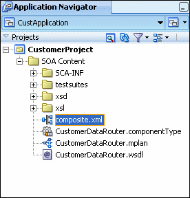
The Application Navigator shown in the upper left part of Figure 2-12 displays the Mediator files. Figure 2-13 shows the files that appear under the SOA Content folder when you create a Mediator in a SOA Composite application.
Figure 2-13 Mediator Files in Application Navigator
Description of "Figure 2-13 Mediator Files in Application Navigator"
As shown in Figure 2-13, a SOA Composite application consists of the following Mediator files:
-
Composite.xml: The file that describes the entire SOA composite application. -
.
componentType: The.componentTypefile describes the services and references for a service component. -
.
wsdl: A Web Service Description File (WSDL) file specifies how other services call a Mediator. A WSDL file defines the input and output messages and operations of a Mediator.
2.3.2 Mediator Editor
The Mediator Editor provides a visual view of the Mediator that you have created. This view is displayed when you perform one of the following actions:
-
Double-click a Mediator in the SOA Composite Editor.
-
Double-click the.mplan file name in the Application Navigator.
2.3.3 Source View
The Source View enables you to view the source code of a Mediator. Click Source at the bottom of the Design window, to view to source code. The code in the source view is immediately updated to reflect the changes in a Mediator.
The following example shows a sample Mediator source code:
<?xml version = '1.0' encoding = 'UTF-8'?>

<!--Generated by Oracle SCA Modeler version 1.0 at [4/16/07 10:05 PM].-->

<Mediator name="CustomerDataRouter" xmlns:xsi="http://www.w3.org/2001/XMLSchema-instance"
xmlns="http://xmlns.oracle.com/sca/1.0/mediator"/>
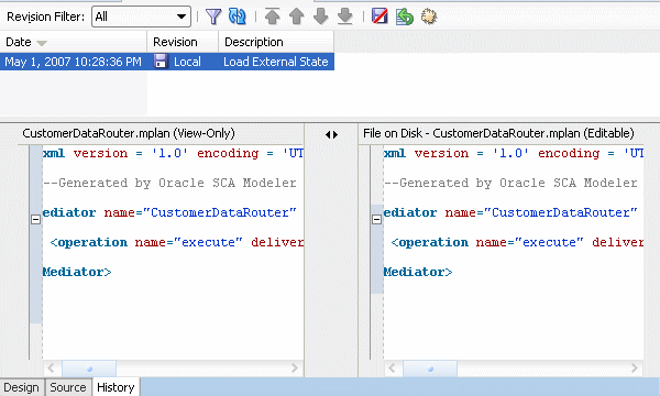
2.3.4 History Window
The History window enables you to perform tasks as viewing the revision history of a file and viewing read-only and editable versions of a file side-by-side. Click History at the bottom of the Design window, to open the History window. Figure 2-14 shows the History view for a Mediator file.
2.3.5 Property Inspector
The Property Inspector enables you to view details about Mediator properties.
2.3.7 Log Window
The Log Window displays messages about the status of validation and compilation.
For more information about Mediator, refer to Part III, "Using the Oracle Mediator Service Component".
2.4 Introduction to the Human Task Editor
You can create a human task service component in the SOA composite application of Oracle JDeveloper and then design it by using the Human Task Editor, which is displayed when you double-click a human task in the SOA Composite Editor.
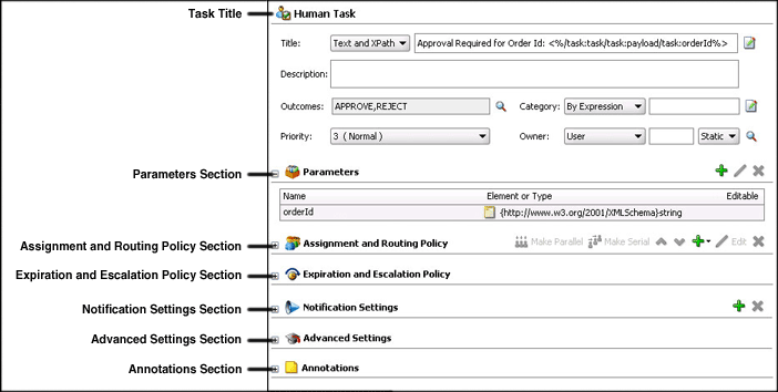
The Human Task Editor consists of the following main sections shown in Figure 2-15. These sections enable you to design the metadata of a human task.
The main sections of the Human Task Editor are described in the following list:
2.4.1 Task Title
This section enables you to specify details such as the task title, description, task outcomes, task category, task priority, and task owner.
2.4.2 Parameters
This section enables you to define the structure (message elements) of the task payload (the data in the task) defined in the XSD file. Figure 2-16 describes the Parameters section of the Human Task Editor.
Figure 2-16 Human Task Editor — Parameters Section

Description of "Figure 2-16 Human Task Editor — Parameters Section"
2.4.3 Assignment and Routing Policy
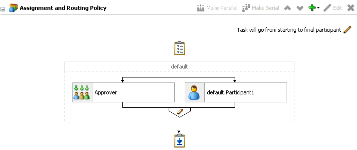
This section enables you to assign participants to the task and create a policy for routing the task through the workflow.
Figure 2-17 shows the Assignment and Routing Policy section of the Human Task Editor.
Figure 2-17 Human Task Editor — Assignment and Routing Policy Section
Description of "Figure 2-17 Human Task Editor — Assignment and Routing Policy Section"
2.4.4 Expiration and Escalation Policy
This section enables you to specify the expiration duration of a task.
Figure 2-18 shows the Expiration and Escalation Policy section of the Human Task Editor.
Figure 2-18 Human Task Editor — Expiration and Escalation Policy Section

Description of "Figure 2-18 Human Task Editor — Expiration and Escalation Policy Section"
2.4.5 Notification Settings
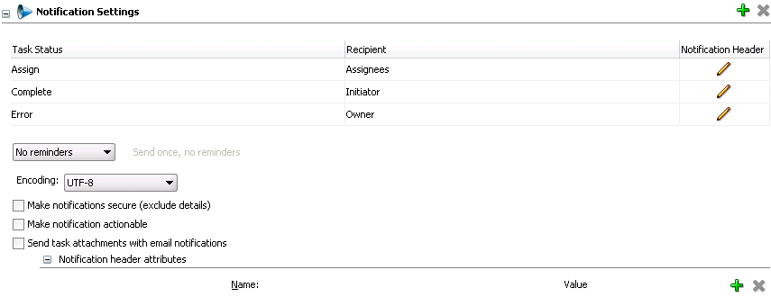
This section enables you to create and send notifications when a user is assigned a task or informed that the status of the task has changed.
Figure 2-19 shows the Notification Settings section of the Human Task Editor (when fully expanded).
Figure 2-19 Human Task Editor — Notification Settings Section
Description of "Figure 2-19 Human Task Editor — Notification Settings Section"
2.4.6 Advanced Settings
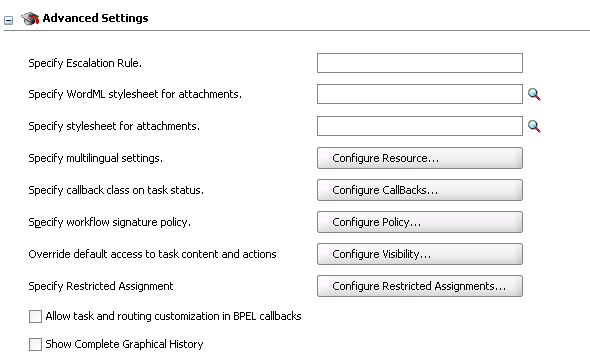
This section enables you to specify advanced design features for the Human Task Editor.
Figure 2-20 shows the advanced settings section of the Human Task Editor.
Figure 2-20 Human Task Editor — Advanced Settings Section
Description of "Figure 2-20 Human Task Editor — Advanced Settings Section"
2.4.7 Annotations
This section enables you to label different attributes of the task definition. Annotations are used with Oracle Business Process Analysis. Annotations are used to label different attributes of the task definition.
For more information on using the main sections of the Human Task Editor to create workflow tasks, see Chapter 25, "Designing Human Tasks."
2.5 Introduction to the Business Rules Designer
You can create a business rules service component in the SOA composite application of Oracle JDeveloper and then design it by using the Business Rules Designer, which is displayed when you double-click a business rule in the SOA Composite Editor.
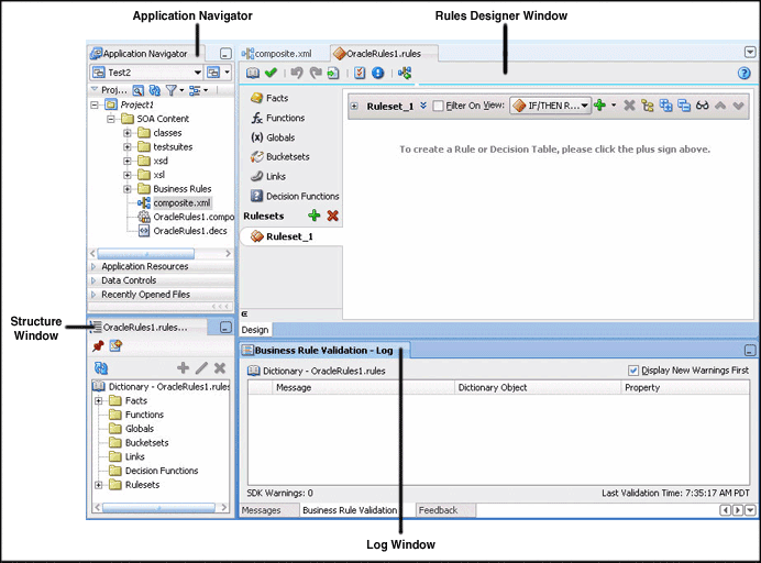
The Business Rules Designer consists of the following main sections shown in Figure 2-21. These sections enable you to work with business rules in Oracle JDeveloper.
Figure 2-21 Rules Designer in Oracle JDeveloper
Description of "Figure 2-21 Rules Designer in Oracle JDeveloper"
The main sections of the Business Rules Designer are described in the following list:
2.5.1 Application Navigator
The Application Navigator displays the files in the project. Each project can only contain one composite. But each composite can have multiple components of either the same type or different types (Business Rules, BPEL process, Oracle Mediator, and human workflow).
As you design business rules, additional files, folders, and elements can appear in the Application Navigator.
2.5.2 Rules Designer Window
The Rules Designer window provides a visual view of the selected dictionary component. You use the Rules Designer navigation tabs to select different parts of the dictionary that you want to work with. The rules designer window displays when you perform one of the following actions:
-
In a composite, double-click a Business Rule component.
-
Double-click the Business Rule component in the SOA Composite Editor.
-
In a BPEL process, double click a business rule.
-
In the application navigator, double-click a business rules dictionary file (a file with the .rules extension)
-
Click the Design tab with a .rules file selected.
Table 2-2 describes where you can find information about working with a dictionary with Rules Designer.
Table 2-2 Rules Designer Navigation Areas Descriptions
For more information about the Rules Designer navigation areas and its descriptions, see Oracle Fusion Middleware User's Guide for Oracle Business Rules.
2.5.3 Structure Window
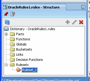
The Structure window offers a structural view of the data in the Business Rule dictionary currently selected in the Rules Designer window. You can perform a variety of tasks from this section, by selecting an element and right-clicking on the element, including:
-
Managing (creating, editing, refreshing, and deleting) elements such as facts, functions, globals, bucketsets, dictionary links, and decision functions
-
Accessing rulesets, rules, and Decision Tables
Figure 2-22 shows the Structure window.
Figure 2-22 Structure Window with Rules Designer Dictionary
Description of "Figure 2-22 Structure Window with Rules Designer Dictionary"
2.5.4 Business Rule Validation Log Window
Rules Designer displays the status of dictionary validation in the business rule validation log, as shown in Figure 2-23.
When a dictionary is invalid, Rules Designer produces a list of warning messages and lists the associated dictionary objects that you can use to locate the dictionary object and to correct the problem. You can safely ignore the validation warnings that you see when you create rules using Rules Designer. The validation warnings are removed as you create the rules, but are shown during the intermediate steps. To test or deploy rules, the associated dictionary must not display warnings.
For more information on business rules validation, see Oracle Fusion Middleware User's Guide for Oracle Business Rules.
Figure 2-23 Rules Designer Business Rule Validation Log
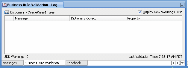
Description of "Figure 2-23 Rules Designer Business Rule Validation Log"
2.6 Introduction to Oracle Enterprise Manager
You can configure, monitor, and manage your SOA composite application during runtime from Oracle Enterprise Manager Fusion Middleware Control Console.
Figure 2-24 shows the Oracle Enterprise Manager Fusion Middleware Control Console with the Deployed Composites tab displayed.
Figure 2-24 Oracle Enterprise Manager Fusion Middleware Control Console
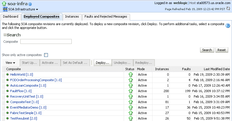
Description of "Figure 2-24 Oracle Enterprise Manager Fusion Middleware Control Console"
For more information about Oracle Enterprise Manager, see Oracle Fusion Middleware Administrator's Guide for Oracle SOA Suite.
